
Mention all the bone guttering techniques for third molar disimpaction. Refer all the text and explain with headings.
bone guttering techniques third molar disimpaction surgical removal impacted wisdom tooth
https://pocketdentistry.com/9-other-methods-for-removal-of-i…
bone guttering technique impacted third molar mandible buccal gutter diagram
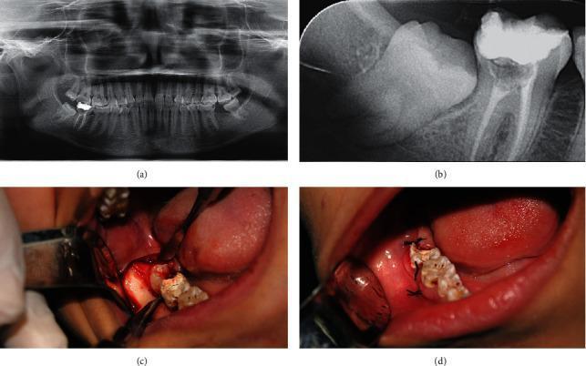
This composite figure illustrates the clinical and radiographic progression of a surgical extraction of an impacted mandibular right third molar. Image (a) is a panoramic radiograph providing a global view of the dental arches, showing the molar's orientation within the mandible. Image (b) is a localized periapical radiograph offering high-detail visualization of the impacted crown, root morphology, and its relationship to the second molar's distal root. Image (c) is an intraoperative clinical photograph demonstrating the surgical field following a pyramidal incision and mucoperiosteal flap elevation. It shows the exposed bone and the partially visible impacted crown with surgical instruments in situ, highlighting the buccal and distal guttering technique. Image (d) is a postoperative clinical photograph showing the extraction site closed with black silk simple interrupted sutures. The series serves as an educational resource for oral and maxillofacial surgery, demonstrating the transition from diagnostic imaging to surgical access and final primary closure in dental impaction management.
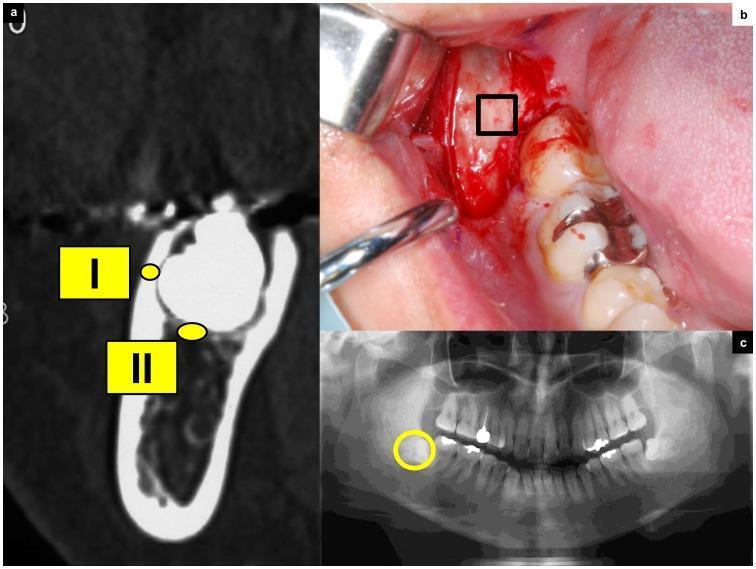
This composite image illustrates the preoperative evaluation and surgical management of an impacted mandibular third molar. (a) A cross-sectional Computed Tomography (CT) scan of the mandible identifies two regions of interest: (I) the high-density buccal cortical bone and (II) the less dense, trabecular cancellous bone adjacent to the tooth crown. (b) An intraoperative clinical photograph shows an envelope flap reflection, exposing the alveolar bone on the buccal aspect of the impacted tooth, with a rectangular marker indicating the site for a bone biopsy. (c) An orthopantomograph (panoramic X-ray) provides a broad view of the dentition, highlighting the impacted third molar (circled) and its spatial orientation within the posterior mandible relative to the second molar and the mandibular canal. This material is designed for dental education, specifically focusing on oral and maxillofacial surgery, radiographic anatomy, and the assessment of bone density (Hounsfield units) in relation to surgical extraction procedures and bone quality pathology.
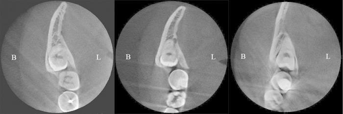
This diagnostic image consists of three parallel Cone Beam Computed Tomography (CBCT) cross-sections of the mandible, demonstrating the classification of an impacted third molar's position relative to the buccal and lingual alveolar bone plates. The sections are labeled B (buccal) and L (lingual) for anatomical orientation. Case (A) shows a buccal position, where the third molar is shifted toward the buccal plate, resulting in a significantly thinner buccal alveolar wall compared to the lingual side. Case (B) illustrates a central position, with the tooth situated equidistant between both cortical plates, showing relatively uniform bone thickness on both aspects. Case (C) demonstrates a lingual position, where the tooth is positioned closer to the lingual cortex, resulting in a thinning of the lingual bone plate. This visual comparison is used in dental medicine and oral surgery for preoperative assessment, risk evaluation of lingual nerve injury, and determining the appropriate surgical approach for extraction based on cortical bone density and thickness.
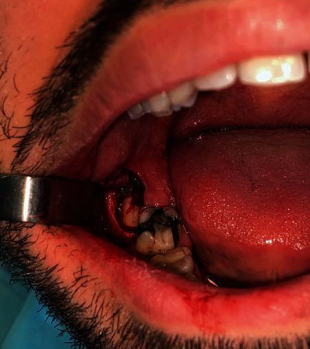
This clinical photograph captures an intraoral surgical procedure involving the extraction of an impacted third molar. The image shows the posterior region of the mandible, where a full-thickness mucoperiosteal flap (triangular Archer's flap) has been reflected to expose the surgical site. A metallic retractor is positioned to hold back the buccal mucosa, providing clear visualization of the mandibular alveolar ridge. An osteotomy has been performed to remove the buccal bone surrounding the crown of the impacted tooth, which is visible in the extraction socket before total removal. There is moderate bleeding and mild inflammation evident in the surrounding gingival tissues, consistent with acute surgical intervention. Adjacent erupted teeth are visible, with one showing potential restorative material. The tongue is lateralized to prevent interference with the surgical field. This image serves as an educational example of intraoral surgical techniques for tooth extraction, highlighting soft tissue management and buccal bone removal via osteotomy.
Bone Guttering Techniques for Third Molar Disimpaction
1. Overview and Principle of Bone Guttering
- Free the tooth from bony obstruction
- Provide a point of application for the elevator
- Create a pathway of delivery for the tooth
- Be minimal so as not to weaken the mandible
2. Approaches to Bone Guttering
A. Buccal Guttering (Primary / Standard Approach)
- The bone on the buccal and distal aspect of the impacted tooth is initially removed down to the level of the cervical line of the tooth.
- If further bone removal is needed, a deep vertical gutter is drilled alongside the buccal aspect of the tooth using a surgical bur (round or fissure bur).
- The gutter extends deep alongside the tooth without sacrificing the outer height of the buccal plate - this is the key difference from simple bone saucerization.
- This creates adequate space (a "trough") around the tooth to permit free displacement.
- Maintains the height and strength of the buccal cortical plate
- Adequate space created for elevator application and tooth delivery
- No risk to the lingual nerve (which can be encountered during lingual-side work)
- As the bur reaches the apex, the inferior alveolar canal may be inadvertently opened, causing brisk hemorrhage from inferior alveolar vessels - controlled with pressure packing or bone wax
- Damage to the inferior alveolar nerve can cause anesthesia over the mental nerve distribution
- In rare cases, the mandibular canal may be buccally placed at a more superior level than normal, increasing the risk of injury
B. Distal Guttering
- A distal gutter is created in continuity with or separately from the buccal gutter
- Required most prominently in distoangular impactions, where the pathway of delivery is directed into the ramus and more distal bone must be removed
- An adequate buccal and distal trough (guttering) is created around the full crown of the tooth to a depth below the cervical line
- A point of elevator application is established on the buccal aspect using the buccal cortical plate as a fulcrum
- The tooth is elevated upward and distally; if there is resistance, the distal portion of the crown is sectioned horizontally and removed before the roots are delivered
C. Combined Buccal and Distal Trough (Guttering) for Deep/Vertical Impactions
- The tooth is first exposed
- A buccal and distal trough (guttering) is created
- The crown is then sectioned in a horizontal fashion
- The roots are elevated in one piece or, if divergent, sectioned and removed separately (distal root removed before mesial)
D. Mesial Guttering (Limited Use)
E. Distolingual Guttering (Specialist Approach)
- Care must be taken to protect the lingual nerve, which can occasionally be encountered in this region
- This approach is generally reserved for specialist use and is carried out under general anesthesia
- The risk to the lingual nerve makes this a non-preferred routine approach under local anesthesia
3. Instruments Used for Guttering
| Instrument | Notes |
|---|---|
| Surgical bur (round or fissure) | Most preferred; continuous irrigation with saline/distilled water required to dissipate frictional heat |
| Rotary handpiece (high-speed surgical) | Does not deliver air spray (to avoid air emphysema); widely used today |
| Chisel and mallet | Used in lingual split technique; not preferred under local anesthesia due to jarring effect and patient intolerance |
Note: High-speed surgical handpieces have largely replaced chisel-and-mallet techniques in modern practice, particularly under local anesthesia. The rotary instrument must never be a standard air-turbine rotor (risk of fatal air emphysema).
4. Buccal Corticotomy - A Special Guttering Variant
- A rectangular window (buccal corticotomy) is outlined over the deeply impacted tooth using a narrow fissure bur
- Mesial and distal cuts are made almost reaching the inferior border of the mandible
- The window is removed with an osteotome
- The impacted molar is divided and removed
- The bony window is then replaced back into its original position
5. Lingual Split Bone Technique (Contrast to Guttering)
- A vertical chisel cut is made in the buccal bone distal to the second molar
- A second horizontal cut joins the first posteriorly
- The chisel bevel is turned lingually and a lingual split is made, removing a disto-lingual piece of bone (saucerization of the socket)
- Developed originally to reduce infection risk
- Associated with more postoperative pain than the bur technique
- The bur/guttering technique produces more swelling but overall the simplified split bone technique has the least morbidity
6. Guttering Applied by Impaction Type
| Impaction Type | Guttering Required |
|---|---|
| Mesioangular | Buccal gutter; distal bone removed to cervical line; minimal mesial guttering |
| Vertical (shallow) | Minimal guttering; elevator applied mesially may be sufficient |
| Vertical (deep, bone-covered) | Buccal + distal trough below cervical line; horizontal crown sectioning |
| Horizontal | Buccal gutter over occlusal, buccal, and distal aspects; crown sectioned distally |
| Distoangular | Most extensive guttering - full buccal + distal trough around the entire crown below cervical line; distal crown section often required |
7. Key Precautions During Guttering
- Inferior alveolar nerve - At risk when guttering reaches the apex; watch for sudden brisk hemorrhage (opening of inferior alveolar canal)
- Lingual nerve - At risk during distolingual bone removal; protect with a Howarth's or Hovell's retractor
- Adjacent second molar - Minimal mesial guttering; keep the bur away from the distal root of the second molar
- Mandibular fracture - Excessive buccal bone removal weakens the mandible; the guttering technique (preserving cortical plate height) is specifically designed to prevent this
- Moderate force only - After guttering, only moderate force should be needed for tooth displacement; if resistance persists, plan for further guttering or tooth sectioning rather than excessive force