
OT IN SURGICAL CONDITIONS 1. Brief review of methods of evaluation and Therapeutic principles. Recommended book(s) for Reference: 1. Pedretti’s Practice skills for physical dysfunction edited by Heidi McHugh Pendleton ,Winifred Schultz Krohn 2. Occupational Therapy for Physical Dysfunction by Mary Vining Radomski, Catherine A Trombly 3. Occupational Therapy and Physical Dysfunction, Principles, Skills and Practice by Ann Turner, Margaret Foster, Sybil E Johnson 4. Introduction to Occupational Therapy by Hussey Subonis ,Chafea O Brien 5. Occupational Therapy and Mental Health edited by Jennifer Creek, Lesley Lougher 6. Mental Health Concepts and Techniques for the Occupational Therapy Assistant by Mary Beth Early 7. Frames of Reference in Psychosocial Occupational Therapy by Mary Ann Bruce, Barbara Borg 8. Willard & Spackman’s Occupational Therapy 9. Occupational Therapy for children by Jane Case Smith 10. Frames of Reference for Pediatric Occupational Therapy by Paula Kramer , Jim Hinojosa
occupational therapy surgical conditions evaluation therapeutic principles Pedretti
Occupational Therapy in Surgical Conditions
Brief Review of Methods of Evaluation and Therapeutic Principles
Overview
PART I: METHODS OF EVALUATION
A. Occupational Profile
- The patient's prior functional level and daily routines
- Social and home environment (stairs, bathroom layout, caregiver availability)
- Vocational and leisure roles
- Patient goals and concerns regarding surgery and recovery
- Cultural and contextual factors (Willard & Spackman)
B. Performance Component Evaluations
1. Range of Motion (ROM)
- Goniometry is the standard tool for measuring joint ROM (both active and passive)
- Pre-operative ROM is documented to set realistic post-op goals
- Particularly important in surgeries involving joints (arthroplasty, tendon repair, fracture fixation)
- Reference: Pedretti's - Chapter on evaluation of joint ROM and muscle strength
2. Muscle Strength Testing
- Manual Muscle Testing (MMT) using the MRC scale (0-5) or Lovett scale
- Dynamometry (grip strength via Jamar dynamometer; pinch strength via pinch meter)
- Surgical scarring, post-op pain, and immobilization can all reduce strength significantly
- Baseline pre-op strength predicts rehabilitation potential
3. Sensation and Neurological Assessment
- Semmes-Weinstein Monofilament Test - assesses light touch and pressure thresholds
- Two-Point Discrimination (static and moving) - critical after nerve repair, hand surgery, or replantation
- Proprioception and Kinesthesia testing - especially relevant after joint replacement
- Pain assessment - VAS (Visual Analogue Scale), numerical rating scales, McGill Pain Questionnaire
- Reference: Radomski & Trombly - evaluation chapters for sensation and pain
4. Edema and Wound Status Assessment
- Volumetric water displacement (most accurate for hand/wrist edema)
- Circumferential tape measurement (quick clinical method)
- Wound observation: scar maturity, hypertrophic scarring, keloid formation, wound healing stages
- Scar assessment tools: Vancouver Scar Scale (VSS), Patient and Observer Scar Assessment Scale (POSAS)
- Reference: Turner, Foster & Johnson - wound and scar management chapters
5. Coordination and Dexterity Testing
- Purdue Pegboard Test - assesses fine motor speed and bilateral coordination
- Minnesota Rate of Manipulation Test - gross and fine dexterity
- Nine-Hole Peg Test (9-HPT) - quick assessment of finger dexterity
- Jebsen-Taylor Hand Function Test - simulates real ADL tasks using timed subtests
6. Activities of Daily Living (ADL) and Functional Assessment
- Functional Independence Measure (FIM) - rates independence across 18 items including self-care, sphincter control, transfers, locomotion, communication, and social cognition
- Barthel Index - measures independence in 10 basic ADL areas
- COPM (Canadian Occupational Performance Measure) - patient-centered, identifies priorities in self-care, productivity, and leisure
- AMPS (Assessment of Motor and Process Skills) - observational measure of ADL task performance
- Reference: Pedretti's and Willard & Spackman
7. Upper Extremity Specific Instruments (Surgical Cases)
- DASH (Disabilities of the Arm, Shoulder and Hand) questionnaire
- QuickDASH - shorter version for quick screening
- MHQ (Michigan Hand Questionnaire) - specifically for hand surgery patients
- PRWE (Patient-Rated Wrist Evaluation) - pain and functional disability post-wrist surgery
8. Cognitive and Psychosocial Assessment
- Cognitive screening (MMSE, MOCA) - especially in elderly surgical patients
- Depression and anxiety screening (PHQ-9, GAD-7)
- Role Checklist and Occupational Self-Assessment (OSA) for psychosocial impact
- Reference: Early (Mental Health Concepts) and Bruce & Borg (Frames of Reference in Psychosocial OT)
9. Environmental and Home Assessment
- Pre-discharge home visit or structured questionnaire
- Assess for fall hazards, accessibility, equipment needs (grab bars, raised toilet seat, ramp)
- Particularly important after lower extremity surgeries, amputation, or major abdominal surgery
PART II: THERAPEUTIC PRINCIPLES
A. Guiding Frames of Reference
| Frame of Reference | Application in Surgical OT |
|---|---|
| Biomechanical | Restoring ROM, strength, endurance in musculoskeletal surgical cases |
| Rehabilitative/Compensatory | Teaching adaptive techniques and equipment use when full recovery is not possible |
| Neurodevelopmental (NDT) | Applied in neurological surgical cases (e.g., post-craniotomy, spinal decompression) |
| Cognitive-Behavioral | Managing post-surgical pain behaviors, fear-avoidance, catastrophizing |
| Model of Human Occupation (MOHO) | Addressing volition, habituation, and performance capacity across the full person |
| Person-Environment-Occupation (PEO) | Modifying environment and tasks to maximize occupational performance |
B. Pre-Operative OT Intervention
- Patient education - surgical procedure, expected limitations, activity precautions
- Pre-operative strengthening exercises - to improve post-op recovery capacity
- Splinting and orthotic preparation - fabricating pre-operative splints where needed (e.g., resting hand splints before tendon surgery)
- ADL training - teaching one-handed techniques before amputations or immobilizing procedures
- Environmental modifications - arranging home prior to surgery to ease the return
- Psychological preparation - addressing anxiety about surgery and recovery expectations
C. Post-Operative Therapeutic Principles
1. Wound and Scar Management
- Scar massage - initiated once wound is fully epithelialized (usually 2-3 weeks post-op)
- Compression garments - for hypertrophic scar prevention (burns, skin grafts, hand surgeries)
- Silicone gel sheets - applied over mature scars to soften and flatten
- Desensitization - for hypersensitive surgical scars using graded textures
2. Edema Management
- Elevation - position limb above heart level
- Compression wrapping - retrograde massage, Coban wrapping for digit edema
- Active ROM exercises - "pump" edema through muscle contraction
- Cold therapy (cryotherapy) - reduces acute post-surgical inflammation
3. Pain Management
- OT uses occupation as a therapeutic modality - engagement in meaningful activity provides distraction and reduces pain perception
- Splinting for pain relief and rest positioning
- TENS (Transcutaneous Electrical Nerve Stimulation) as adjunct
- Desensitization programs for post-surgical allodynia or hyperalgesia
- Relaxation techniques and mindfulness
4. ROM and Strength Restoration
- Active-assisted and passive ROM exercises progressed according to tissue healing stages
- Tendon gliding exercises after flexor/extensor tendon repairs
- Joint mobilization (within precautions) for capsular tightness
- Progressive resistive exercises (PRE) using putty, theraband, weights
- Inflammatory phase (0-5 days): protection, edema control, pain management
- Proliferative phase (5-21 days): gentle ROM, wound care
- Remodeling phase (21 days - 2 years): progressive strengthening, scar management
5. Splinting and Orthotics
- Static splints: immobilize for protection (post-fracture fixation, nerve repair)
- Dynamic splints: provide controlled force to restore ROM (e.g., dynamic extension splint after Dupuytren's release)
- Serial static splints: progressively stretched to increase ROM
- Functional position splints: maintain safe positioning between exercises
- Reference: Pedretti's - orthotic intervention chapters
6. ADL Training and Functional Rehabilitation
- Retraining in self-care tasks: dressing, grooming, bathing, toileting, feeding
- One-handed techniques for temporary or permanent upper limb impairment
- Adaptive equipment: button hooks, long-handled reachers, dressing sticks, sock aids, non-slip mats
- Energy conservation and work simplification principles - particularly for cardiothoracic or abdominal surgery patients
- Joint protection principles after arthroplasty or joint reconstruction
7. Transfers, Mobility, and Precautions
- Teaching safe transfers (bed-to-chair, chair-to-standing) within surgical precautions
- Post-hip arthroplasty: hip precautions (avoid >90° flexion, internal rotation, adduction across midline)
- Post-spinal surgery: back precautions, log-rolling techniques
- Post-sternotomy (cardiac/thoracic): sternal precautions (no pushing/pulling with arms)
8. Upper Extremity Surgical Conditions - Specific Protocols
| Condition | Key OT Therapeutic Focus |
|---|---|
| Flexor tendon repair | Kleinert or Duran protocol - early controlled mobilization to prevent adhesions |
| Extensor tendon repair | Zone-specific protocols; dynamic extension splinting |
| Fractures (hand/wrist) | Protective orthosis → progressive ROM → strengthening |
| Nerve repair (peripheral) | Sensory re-education, desensitization, motor re-education |
| Replantation/amputation | Residual limb shaping, prosthetic training, phantom pain management |
| Dupuytren's contracture release | Splinting at full extension, aggressive ROM program |
| Carpal tunnel release | Scar management, progressive grip strengthening, ergonomic re-education |
| Shoulder arthroplasty | Codman pendulum exercises → active ROM → functional strengthening |
9. Vocational and Instrumental ADL Rehabilitation
- Work hardening programs for return-to-work after surgery
- Simulated work tasks, job-specific activity analysis
- Home management retraining - cooking, cleaning, laundry with modifications
- Driving assessment and training post-surgery where applicable
10. Discharge Planning and Community Reintegration
- Equipment provision (splints, adaptive aids, mobility equipment)
- Home modification recommendations
- Community resources referral
- Patient and caregiver education
- Follow-up OT in outpatient/community setting
PART III: Special Considerations
Pediatric Surgical Cases
- Evaluation is play-based and age-appropriate (reference: Case-Smith, Kramer & Hinojosa)
- Developmental level must be considered alongside surgical condition
- Family education and involvement is central
- Splints must be designed and monitored carefully for growing limbs
Elderly Surgical Patients
- Pre-existing cognitive decline affects compliance with precautions
- Polypharmacy, frailty, and fall risk must be integrated into planning
- Longer healing times, reduced physiological reserve
- Reference: Pedretti's Chapter 46 (Special Needs of the Older Adult)
Psychosocial and Mental Health Dimensions
- Body image changes after amputation, colostomy, mastectomy, or disfiguring surgery
- Grief response, adjustment disorder, PTSD following traumatic surgical events
- OT addresses role disruption, loss of occupational identity
- Reference: Creek & Lougher, Early, Bruce & Borg
Summary
| Phase | Evaluation Focus | Therapeutic Focus |
|---|---|---|
| Pre-operative | Baseline ROM, strength, function, ADL status, home environment | Education, prehabilitation, equipment prep, psychosocial readiness |
| Acute post-op | Edema, pain, wound, early ROM, cognitive status | Edema/pain management, protected ROM, positioning, basic ADL |
| Sub-acute | Strength, coordination, endurance, ADL performance | Progressive exercise, splinting, ADL retraining, adaptive equipment |
| Rehabilitation | Functional task performance, work capacity, community roles | Work hardening, home management, community re-integration |
- Pedretti's Occupational Therapy: Practice Skills for Physical Dysfunction, Pendleton & Schultz-Krohn
- Occupational Therapy for Physical Dysfunction, Radomski & Trombly
- Occupational Therapy and Physical Dysfunction, Turner, Foster & Johnson
- Willard & Spackman's Occupational Therapy
- Occupational Therapy for Children, Case-Smith
- Mental Health Concepts and Techniques for the OT Assistant, Early
- Frames of Reference in Psychosocial Occupational Therapy, Bruce & Borg
2.Objectives and role of Occupational Therapy in. A. Hand Injury a. Review of hand evaluation. b. Nerve injuries - classification, repair process, management of Ulnar, Median and Radial nerve injuries c. Tendon injuries-repair process & post operative management of flexor and extensor tendon injuries. d. Soft tissue injuries e. Fractures f. Management of crush injury with emphasis on hand rehabilitation Recommended book(s) for Reference: 1. Pedretti’s Practice skills for physical dysfunction edited by Heidi McHugh Pendleton ,Winifred Schultz Krohn 2. Occupational Therapy for Physical Dysfunction by Mary Vining Radomski, Catherine A Trombly 3. Occupational Therapy and Physical Dysfunction, Principles, Skills and Practice by Ann Turner, Margaret Foster, Sybil E Johnson 4. Introduction to Occupational Therapy by Hussey Subonis ,Chafea O Brien 5. Occupational Therapy and Mental Health edited by Jennifer Creek, Lesley Lougher 6. Mental Health Concepts and Techniques for the Occupational Therapy Assistant by Mary Beth Early 7. Frames of Reference in Psychosocial Occupational Therapy by Mary Ann Bruce, Barbara Borg 8. Willard & Spackman’s Occupational Therapy 9. Occupational Therapy for children by Jane Case Smith 10. Frames of Reference for Pediatric Occupational Therapy by Paula Kramer , Jim Hinojosa
nerve injury classification Seddon Sunderland diagram
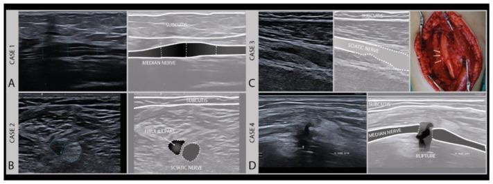
This composite educational graphic illustrates various degrees of axonal nerve damage using high-frequency musculoskeletal ultrasound (MSKUS) and intraoperative photography. The content is divided into four clinical cases, categorized by Sunderland's classification of nerve injury. Case 1 (A) shows a longitudinal US image of a median nerve demonstrating focal swelling and hypoechogenicity with intact fascicles (Sunderland Grade II). Case 2 (B) presents a transverse US image of a sciatic nerve (peroneal/fibular part) showing a heterogeneous, enlarged lesion. Case 3 (C) includes a longitudinal US and an intraoperative photograph showing severe sciatic nerve damage (Sunderland Grade III), where the intraoperative view confirms structural alterations corresponding to sonographic irregularities. Case 4 (D) displays a longitudinal US image of a median nerve featuring a complete loss of continuity and a visible rupture (Sunderland Grade V), typical of neurotmesis. Each case is accompanied by an anatomical schematic overlay identifying the subcutis and the specific nerve pathology. This resource is designed for intermediate to advanced medical learners focusing on neurology, radiology, and trauma surgery.
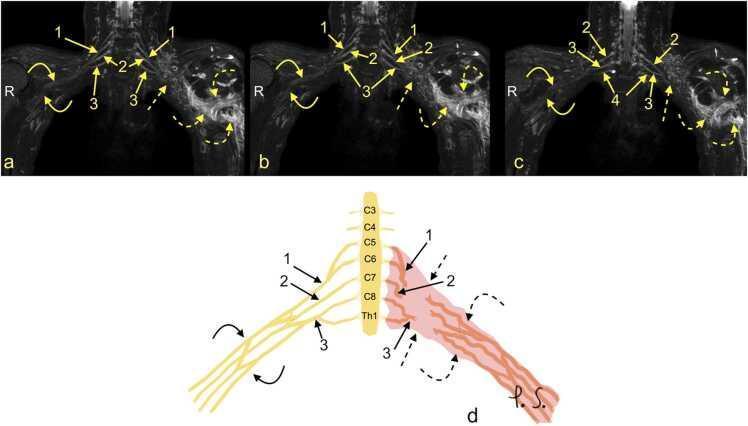
This composite educational resource comprises three Magnetic Resonance Neurography (MRN) coronal views (a, b, c) and a correlating schematic anatomical diagram (d) illustrating a severe traumatic brachial plexus injury. The right side of the images displays normal brachial plexus anatomy, with continuous nerve structures including the upper trunk (1), middle trunk (2), C8 root (3), and Th1 root (4). In contrast, the left side demonstrates a total rupture of the brachial plexus (dashed arrows). This injury is characterized by the complete discontinuity of the neural trunks and cords, accompanied by a large axillary cavity hematoma (curved dashed arrows). The schematic (d) highlights the side-to-side difference, showing the organized right-sided roots (C5-Th1) and trunks versus the disorganized, hemorrhagic area on the left. This material is designed for advanced medical education in radiology and neurosurgery, focusing on diagnostic imaging features of high-grade nerve trauma, specifically Seddon grade 3-5 injuries (neurotmesis) and the identification of postganglionic plexopathy.
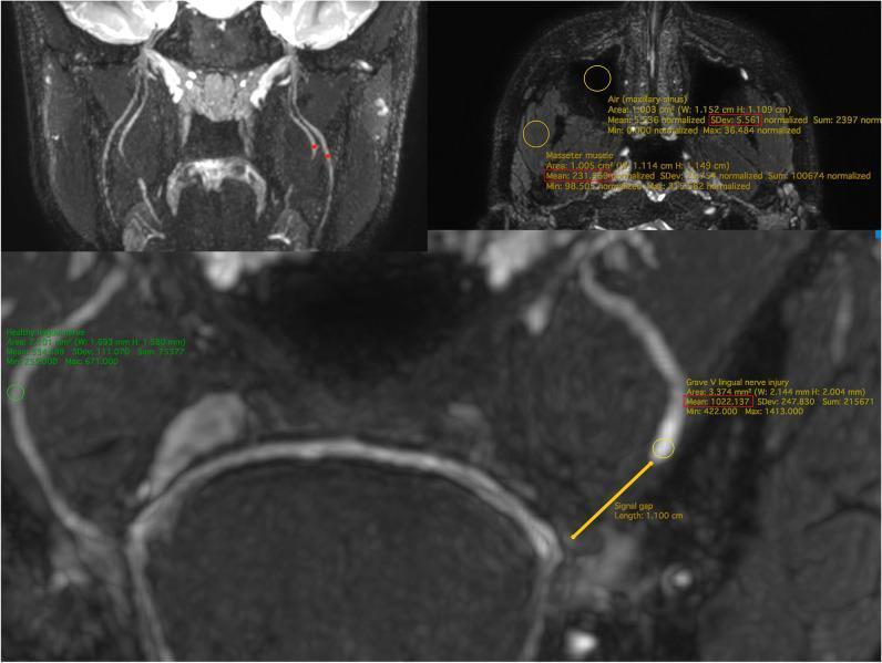
Diagnostic Magnetic Resonance Neurography (MRN) of the trigeminal nerve branches using coronal 3D CRANI sequences. The image is divided into panels demonstrating quantitative assessment methods for nerve injury. The upper panels show normal anatomy and calibration techniques: the left upper panel highlights the lingual nerve (LN) and inferior alveolar nerve (IAN) with regions of interest (ROI) at anatomical landmarks; the right upper panel shows ROI placement in the masseter muscle and maxillary sinus air to establish baseline signal intensity and noise for apparent signal-to-noise ratio (aSNR) calculations. The lower, enlarged panel demonstrates a Grade V lingual nerve injury (Sunderland classification). A definitive signal gap of 1.100 cm is measured between the proximal and distal nerve stumps, indicating complete transection. Numerical data overlays provide mean signal intensity and standard deviation within the ROIs, used to calculate the nerve-muscle contrast-to-noise ratio (aNMCNR). This imaging modality is used for surgical planning and objective stratification of post-traumatic nerve injuries in maxillofacial surgery.
hand anatomy zones flexor tendon
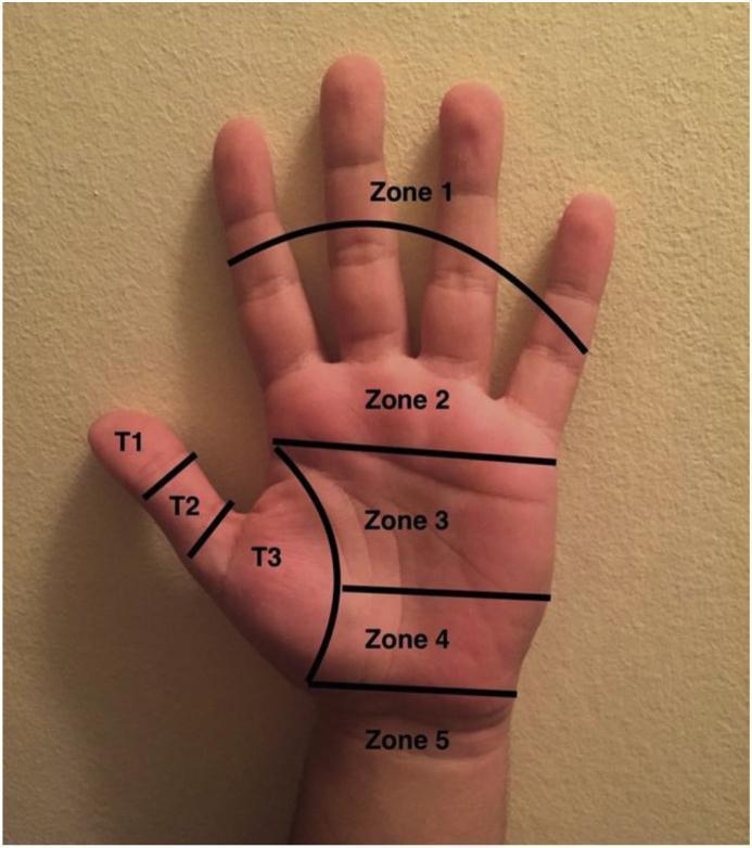
This clinical photograph displays the volar (palmar) surface of a human hand, annotated to illustrate the Verdan classification system for flexor tendon injury zones. The image serves as an educational anatomical diagram for hand surgery and trauma management. The hand is divided into five primary zones and three specific thumb zones (T1–T3) using black demarcation lines. Zone 1 covers the distal segments of the fingers; Zone 2 (often called 'No Man's Land') extends from the distal palmar crease to the mid-portion of the middle phalanges; Zone 3 encompasses the central palm (lumbrical origin); Zone 4 corresponds to the carpal tunnel region; and Zone 5 includes the area proximal to the wrist crease (forearm). The thumb is separately classified into T1 (distal to the IP joint), T2 (between the MCP and IP joints), and T3 (thenar eminence). This visual guide is essential for medical students and surgical residents to understand the prognosis and surgical approach for flexor tendon repairs based on the anatomical site of injury.
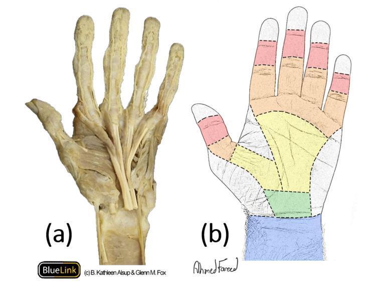
This medical visual consists of two parts illustrating the anatomy of the flexor tendons and the five surgical flexor zones of the hand. Image (a) is a cadaveric dissection of a left hand and distal forearm, showcasing the longitudinal orientation of the flexor digitorum tendons. The tendons are visible as robust, whitish fibrous cords emerging from the carpal tunnel and splaying out across the palm toward each digit. Image (b) is a color-coded surface anatomy diagram representing the five surgical flexor zones used in orthopedic surgery to classify injuries. Zone I (red) is the most distal, extending from the flexor digitorum profundus (FDP) insertion to the flexor digitorum superficialis (FDS) insertion. Zone II (orange), often termed 'no man's land,' spans the fingers from the FDS insertion to the distal palmar crease. Zone III (yellow) covers the central palm. Zone IV (green) corresponds to the carpal tunnel region, and Zone V (blue) extends proximally from the carpal tunnel into the forearm's musculotendinous junction.
ulnar nerve claw hand deformity median nerve ape hand
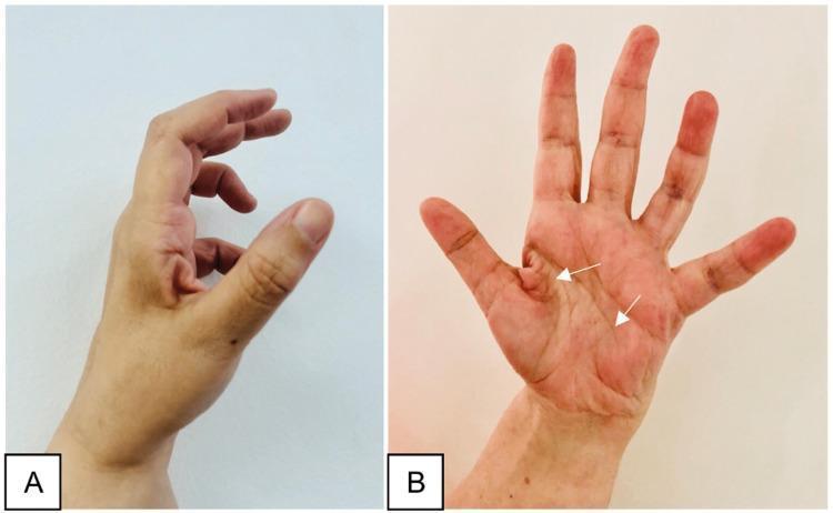
Two-panel clinical photograph demonstrating the late sequelae of a peripheral nerve injury in the hand, specifically illustrating features of ulnar nerve palsy. Image A (lateral view) shows a classic 'claw hand' deformity, characterized by hyperextension at the metacarpophalangeal (MCP) joints and flexion at the interphalangeal (IP) joints, most prominent in the ring and little fingers. The thumb appears adducted and flexed. Image B (anterior/palmar view) displays generalized muscle atrophy of the hand, with significant hollowing of the hypothenar eminence and interosseous spaces (indicated by white arrows). Notably, the thenar eminence remains relatively spared, suggesting the median nerve's innervation to the thenar muscles is intact. This combination of clawing and selective intrinsic muscle wasting is an important educational marker for localizing nerve lesions to the distal ulnar nerve (e.g., Guyon's canal or post-surgical complication). The images illustrate the clinical presentation of chronic motor deficit and the characteristic postural changes resulting from unbalanced muscle pull in the hand.
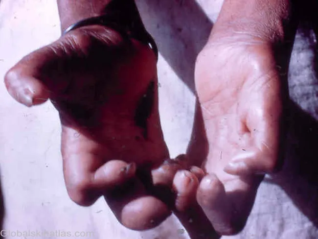
This clinical photograph captures bilateral hands showing claw hand deformity due to early peripheral nerve involvement from tuberculoid leprosy. The flexion contractures of the fingers result from intrinsic muscle wasting (interosseous muscles, thenar, and hypothenar groups) secondary to chronic neuritis with thickened nerves. The palmar aspect highlights impaired intrinsic function with partial lumbrical loss creating a characteristic posture: hyperextension at the metacarpophalangeal joints with flexion of the interphalangeal joints, and evident weakness in grip and dexterity. Nerves involved are classically thickened and tender in Hansen's disease, often involving the ulnar nerve predominantly with contribution from the median nerve. Clinically, this finding signals early sensory-motor neuropathy and potential progression to disability if untreated. The image is a color clinical photograph from Global Skin Atlas, credited to Dr. Ian McColl, illustrating public health relevance of leprosy neuropathy in endemic regions. Notably, the thumbs and other digits may appear relatively spared initially while intrinsic hand muscles disproportionately atrophy. This deformity is important for differential diagnosis against traumatic ulnar neuropathy, diabetic neuropathy, and other causes of clawing. It informs functional prognosis, guides nerve function assessment, and supports educational depiction of Hansen's disease nerve involvement for medical trainees and researchers.

Two-panel clinical photograph demonstrating the physical manifestations of a severe, chronic ulnar nerve injury. Panel (a) shows the dorsal aspect of the hand, highlighting significant muscle wasting (atrophy) of the ulnar-innervated intrinsic muscles. This is visible as sunken, hollowed interosseous spaces between the metacarpals. Panel (b) illustrates a classic 'ulnar claw hand' deformity (main en griffe) from a palmar view. The fourth (ring) and fifth (small) digits exhibit characteristic positioning: hyperextension at the metacarpophalangeal (MCP) joints combined with flexion at the proximal and distal interphalangeal (PIP and DIP) joints. The first (thumb), second (index), and third (middle) fingers remain relatively unaffected due to their median nerve innervation. These signs are indicative of the loss of lumbrical and interossei function, leading to muscular imbalance in the hand. The clinical context suggests these findings resulted from ulnar nerve damage following an attempted Nexplanon® implant removal in the upper arm.
radial nerve wrist drop splint dynamic
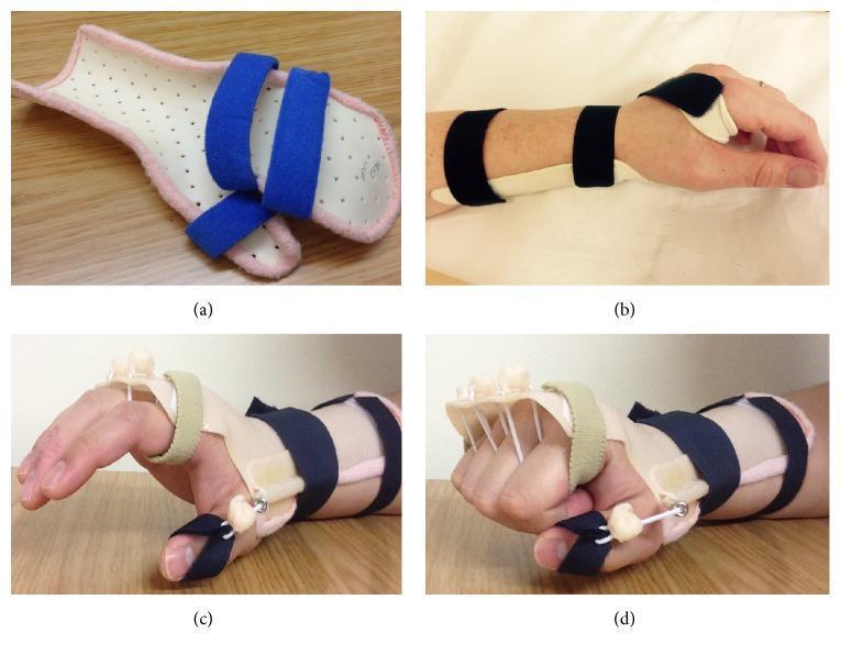
A composite clinical photograph showcasing various orthotic devices utilized in the management of radial nerve palsy. (a) A static resting hand splint composed of a white perforated thermoplastic base with a pink padded liner and blue hook-and-loop straps, designed to maintain the hand and wrist in a functional neutral position. (b) A volar wrist-extension splint applied to a patient, featuring a dorsal hand strap to prevent wrist drop. (c) and (d) demonstrate a dynamic extension orthosis in use. This complex device utilizes a dorsal thermoplastic forearm shell and a series of elastic outriggers or tension wires attached to finger slings. The mechanism provides passive assisted extension of the metacarpophalangeal (MCP) joints and thumb, compensating for the loss of extensor muscle function characteristic of radial nerve injury, while allowing for active finger flexion. These orthoses are critical in hand therapy to prevent contractures, maintain joint mobility, and improve functional grasp during nerve recovery.
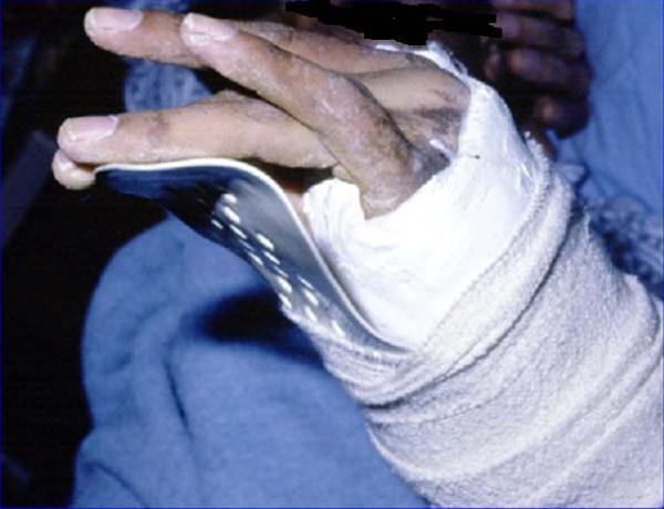
This clinical photograph shows the forearm and hand of a 25-year-old patient who sustained a radial neck fracture resulting in 'wrist drop' due to radial nerve palsy. The forearm is immobilized in a bulky white plaster-of-Paris cast and compression bandaging. A volar cock-up splint, constructed from metallic or rigid synthetic material with visible circular perforations for ventilation, extends from the palm to support the fingers and stabilize the wrist in a functional neutral or slightly extended position. This orthotic intervention is critical to prevent contractures and manage the motor deficit associated with radial nerve injury. The skin of the visible fingers appears dry with evidence of minor ecchymosis or post-traumatic discoloration on the dorsal aspect of the hand. The image serves as an educational example of traumatology management, specifically the conservative or post-surgical immobilization of peripheral nerve injuries following proximal radius fractures.
hand evaluation grip strength goniometry assessment
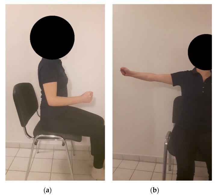
Two-panel clinical photograph demonstrating standardized testing positions for upper limb clinical assessment, likely related to grip strength or kinesiologic evaluation. (a) Side profile showing the patient in a seated position with the right upper arm adducted (neutral beside the trunk) and the elbow flexed at 90 degrees; the hand is clenched in a neutral grip. (b) Frontal view showing the patient in a seated position with the right arm abducted 90 degrees at the shoulder and externally rotated 90 degrees, positioning the forearm perpendicular to the torso. These images illustrate the 'lower' and 'upper' grip testing positions used in physical therapy and occupational medicine to assess musculoskeletal function, range of motion, and grip endurance under different mechanical loads on the shoulder and elbow complexes.
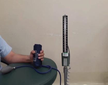
Clinical photograph of a patient's hand being used to assess hand grip strength using a modified mercury sphygmomanometer. The setup includes a dark blue blood pressure cuff that has been rolled into a cylindrical shape to fit the patient's palm, connected via blue flexible tubing to a hand-held inflation bulb and a vertical mercury-filled column scale. The scale is mounted on a metallic base and shows numerical gradations for pressure measurement in mmHg. This clinical assessment technique is often utilized in postoperative hand rehabilitation, such as after ulnar claw hand deformity correction, to provide a reproducible and reliable measurement of functional grip strength. The photograph captures the educational application of standard diagnostic equipment for monitoring recovery in orthopedic and plastic surgery contexts.
Occupational Therapy in Hand Injury
Objectives, Role, and Comprehensive Review
OBJECTIVES OF OT IN HAND INJURY
- Restore maximum functional use of the hand for occupational performance
- Prevent complications - contractures, adhesions, deformity, disuse atrophy
- Manage pain, edema, and scar tissue
- Fabricate and monitor orthotic devices
- Retrain sensorimotor function and fine motor skills
- Facilitate return to self-care, work, and leisure roles
A. REVIEW OF HAND EVALUATION
1. Clinical History and Occupational Profile
- Dominant hand, occupation, hobbies, and prior hand conditions
- Mechanism, timing, and site of injury
- Surgical procedures performed (type of repair, fixation, grafts)
- Precautions communicated by the surgeon
2. Observation and Inspection
- Posture of the hand at rest (abnormal postures signal nerve/tendon involvement)
- Skin color, trophic changes, sweating, hair loss (autonomic nerve signs)
- Wound/scar status, swelling, atrophy of thenar, hypothenar, or interossei
3. Edema Assessment
- Volumetric water displacement - most accurate for the whole hand
- Circumferential tape measurement - practical for individual digits
- Graded: pitting vs. non-pitting; brawny vs. soft
4. Range of Motion (ROM)
- Goniometry - finger goniometer for IP and MCP joints
- Record Active ROM (AROM) and Passive ROM (PROM) separately
- Total Active Motion (TAM) score: sum of flexion at MCP + PIP + DIP minus extension deficit - standard measure in tendon repair outcomes
- TAM formula: TAM = (MCP flexion + PIP flexion + DIP flexion) - (MCP extension deficit + PIP extension deficit + DIP extension deficit)
- Normal TAM: 260° per finger
5. Muscle Strength
- Manual Muscle Testing (MMT) for wrist, thumb, and digit muscles
- Jamar Dynamometer - grip strength in 5 handle positions (produces a bell curve in normals)
- Pinch gauge - lateral (key) pinch, tip pinch, and 3-point (chuck) pinch
- Both sides compared; normative data corrected for age and gender
6. Sensory Evaluation
- Semmes-Weinstein Monofilament Test (SWMT) - assesses protective sensation and light touch thresholds; gold standard for nerve recovery monitoring
- Static Two-Point Discrimination (s2PD) - tests innervation density; normal <6 mm
- Moving Two-Point Discrimination (m2PD) - tests functional recovery; recovers before static
- Tinel's Sign - percussion along nerve course; advances distally as nerve regenerates
- Wrinkle Test - immerse in water; denervated skin does NOT wrinkle
- Ninhydrin Sweat Test - sympathetic denervation causes absent sweating; prints on paper
7. Coordination and Dexterity
- Nine-Hole Peg Test (9-HPT)
- Purdue Pegboard Test
- Minnesota Rate of Manipulation Test
- Jebsen-Taylor Hand Function Test - 7 subtests simulating ADL tasks
8. Functional and Occupational Performance
- DASH / QuickDASH
- Michigan Hand Questionnaire (MHQ)
- COPM - patient identifies priority occupational goals
- Direct observation of task performance (gripping, pinching, writing, dressing)
9. Scar Assessment
- Vancouver Scar Scale (VSS) - rates pliability, vascularity, height, pigmentation
- Patient and Observer Scar Assessment Scale (POSAS)
B. NERVE INJURIES
Classification
| Seddon | Sunderland | Structural Injury | Prognosis |
|---|---|---|---|
| Neurapraxia | Grade I | Focal demyelination; axon intact | Full recovery in days to 3 months; no Wallerian degeneration |
| Axonotmesis | Grade II | Axon disrupted; endoneurium intact | Good recovery; Wallerian degeneration; regenerates ~1 mm/day |
| Axonotmesis | Grade III | Axon + endoneurium disrupted; perineurium intact | Incomplete recovery; scarring |
| Axonotmesis | Grade IV | Axon + endoneurium + perineurium disrupted; epineurium intact | Poor spontaneous recovery; neuroma-in-continuity |
| Neurotmesis | Grade V | Complete nerve transection | No spontaneous recovery; surgical repair essential |
| - | Grade VI | Mixed injury | Variable |
Nerve Repair Process
- Wallerian degeneration occurs distal to the lesion in grades II-V - distal axon degenerates within 48-72 hours
- Schwann cell proliferation creates tubes (bands of Büngner) guiding regenerating axons
- Regeneration rate: approximately 1 mm per day (or 1 inch per month)
- Surgical repair options: primary neurorrhaphy, nerve grafting (sural nerve), nerve conduits
- Sensory re-education begins when protective sensation returns (S3 on MRC scale)
Management of Specific Nerve Injuries
i. Ulnar Nerve Injury
- Loss of intrinsic hand muscles: all interossei, hypothenar muscles (abductor digiti minimi, flexor digiti minimi, opponens digiti minimi), medial two lumbricals
- Loss of adductor pollicis (weak pinch - Froment's sign positive)
- Sensory loss: little finger and ulnar half of ring finger, ulnar palm
- Hyperextension of MCP joints (unopposed long extensors) + flexion of IP joints (unopposed long flexors)
- More pronounced in ring and little fingers (index and middle partially spared by median-innervated lumbricals)
- Paradox of the claw: high ulnar nerve lesions produce LESS clawing (FDP to 4th and 5th also paralyzed)
- Anti-claw splint / lumbrical bar splint: blocks MCP hyperextension, allowing IP extension by long extensors - prevents contracture and improves function immediately
- Knuckle-bender splint if PIP flexion contracture develops
- Sensory re-education: graded texture desensitization and discrimination training once nerve regeneration begins (Tinel advances; s2PD returns)
- Strengthening: intrinsic muscle re-education with biofeedback and purposeful activities
- ADL adaptation: lateral pinch weakness - key holder, built-up handles; writing aids
- Froment's sign compensatory training: stability aids for lateral pinch tasks
ii. Median Nerve Injury
- At wrist: loss of thenar muscles (opponens pollicis, abductor pollicis brevis, flexor pollicis brevis superficial head), lateral two lumbricals
- Sensory loss: palmar surface of thumb, index, middle, and radial half of ring finger - critical functional area for precision grip
- At elbow/forearm: additionally loses FDS, FDP to index and middle, FCR, pronator teres, pronator quadratus, flexor pollicis longus
- Thenar wasting - flat palm on thumb side
- Thumb lies in plane of palm (loss of opposition)
- Loss of index and middle finger PIP flexion at high lesion
- Opponens splint (C-bar / short opponens splint): maintains thumb in abduction/opposition for functional pinch and grip; especially at wrist-level lesions
- Sensory re-education is CRITICAL - median nerve supplies the precision sensory area; without sensation, hand function is severely limited even with motor recovery
- Phase I (protective sensation, S2-S3): localization training, texture differentiation
- Phase II (discriminative sensation, S3+-S4): two-point, stereognosis, Dellon sensory re-education program
- Desensitization: for hypersensitivity at thenar scar following carpal tunnel release or nerve repair
- Opposition retraining: opposition exercises using pegs, putty, pinch activities
- ADL compensation: button hooks, Velcro fasteners, built-up pen grips to compensate for precision loss
iii. Radial Nerve Injury
- Wrist drop (loss of wrist extensors - ECRL, ECRB)
- Loss of finger and thumb MCP extension (extensor digitorum, EIP, EDM, EPL, EPB)
- Loss of thumb abduction (APL)
- Sensory loss: limited - dorsoradial hand and thumb web space (relatively minor functionally)
- Note: PIN (posterior interosseous nerve) injury spares wrist extension (ECRL via branch above spiral groove)
- Static wrist cock-up splint: maintains wrist in 20-30° extension for functional hand use; prevents overstretching of extensors
- Dynamic wrist and finger extension splint (outrigger splint): provides spring-loaded extension of wrist and MCPs while allowing active flexion - restores functional grasp during nerve recovery period
- No intrinsic splinting needed (intrinsics are medially/ulnar-innervated)
- Passive ROM exercises: prevent tightening of wrist and finger flexors
- ADL adaptation: built-up handles for grip, modified keyboard/writing setup
- Sensory re-education: less critical than median; dorsal hand sensation less functionally significant
C. TENDON INJURIES
Flexor Tendon Anatomy and Zones
| Zone | Location | Clinical Significance |
|---|---|---|
| Zone I | Distal to FDS insertion (DIP level) | FDP only; isolated DIP flexion loss (jersey finger) |
| Zone II | From A1 pulley to FDS insertion ("No Man's Land") | Most difficult - both FDS and FDP in tight fibro-osseous tunnel |
| Zone III | Palm (lumbrical origin to A1 pulley) | Better healing environment |
| Zone IV | Within carpal tunnel | FPL and finger flexors + median nerve close together |
| Zone V | Forearm proximal to carpal tunnel | Good prognosis; multiple structures but more space |
Repair Process
-
Tendon healing occurs in 3 phases:
- Inflammatory (0-5 days): extrinsic healing by ingrowth of fibroblasts; strength weak
- Proliferative/Fibroplasia (5-21 days): collagen synthesis; adhesion formation risk highest here
- Remodeling (3 weeks - 6 months): collagen matures; strength increases
-
Key surgical advances: core suture + epitendinous suture techniques (4-strand or 6-strand repairs are now standard) allow earlier active mobilization
Post-Operative Management of Flexor Tendon Injuries
1. Immobilization Protocol (Historical/Conservative)
- 3-4 weeks strict immobilization in protective splint (wrist 20-30° flexion; MCPs 45-60° flexion)
- Used for unreliable patients, children, or very weak repairs
- Highest adhesion rate
2. Early Passive Mobilization - Kleinert Protocol
- Dorsal blocking splint: wrist 20-30° flexion, MCP 45-60° flexion
- Rubber band traction from fingernail to forearm splint - holds fingers in flexion passively
- Patient actively extends fingers against the elastic traction; rubber band passively returns to flexion
- Glides repaired tendon within its sheath, preventing adhesion formation
- Active extension is safe because it doesn't stress the repaired flexor
3. Early Active Mobilization - Duran Protocol / Modified Duran
- Dorsal blocking splint (same position)
- Gentle controlled passive flexion of PIP and DIP with therapist or self-mobilization
- 8 repetitions each PIP, DIP, DIP + PIP, composite passive flexion - repeated 4-6 times/day
- Proven to reduce adhesion formation without rupturing repair
4. Early Active Mobilization - Place-and-Hold / Synergistic Protocol
- With stronger core sutures (4-6 strand): patient places finger in flexion passively, then actively holds position
- "True active flexion" protocols now used with strong repairs
| Phase | Weeks Post-Op | Key Interventions |
|---|---|---|
| Phase I (Protection) | 0-3 | Dorsal blocking splint; edema control; passive flexion (Duran)/elastic traction (Kleinert); wound care |
| Phase II (Controlled Mobilization) | 3-6 | Increase active flexion; discontinue rubber bands at ~4 wks; begin composite fist; scar massage |
| Phase III (Progressive Loading) | 6-8 | Begin light resistance; putty exercises; progressive strengthening |
| Phase IV (Resistive) | 8-12 | Full resistive exercises; work simulation; sport-specific activities |
| Phase V (Return to Full Function) | 12+ | Work hardening; ADL retraining; occupation-specific tasks |
Post-Operative Management of Extensor Tendon Injuries
| Zone | Location | Injury/Condition |
|---|---|---|
| I | DIP joint | Mallet finger (disrupted terminal tendon) |
| II | Middle phalanx | |
| III | PIP joint | Boutonniere deformity (central slip rupture) |
| IV | Proximal phalanx | |
| V | MCP joint | Fight bite / sagittal band injury |
| VI | Dorsum of hand | |
| VII | Wrist (retinaculum) | |
| VIII | Distal forearm |
- DIP joint held in extension splint (Stack splint or custom thermoplastic) continuously for 6-8 weeks
- DIP must NEVER drop into flexion during splint wear - patient education essential
- After 6-8 weeks: begin gentle active DIP flexion; continue night splinting 4-6 more weeks
- Post-surgical: PIP extension splint (static at 0°) full-time for 6 weeks; DIP left free and encouraged to flex actively (keeps lateral bands mobile)
- After 6 weeks: controlled PIP flexion; dynamic PIP extension splint if needed
- Extensor tendons are thinner, more prone to adhesion and rupture than flexors
- Early passive extension protocols used for zone V-VIII
- Short arc motion (SAM) protocol: small arc of active motion from 0° to 30° extension - proven to prevent adhesions while protecting repair
- Relative motion splinting (yoke splint): injured finger held in slight MCP extension relative to adjacent fingers - allows function while protecting repair
D. SOFT TISSUE INJURIES
OT Role:
- Wound observation and dressing application (in some OT practice settings)
- Scar management begins once wound is fully epithelialized (2-3 weeks):
- Scar massage: circular friction with neutral oil/cream, 5-10 min/session, 2-3x/day
- Compression: Coban self-adherent wrap, Otoform/silicone putty, custom compression gloves
- Silicone gel sheets/pads: applied over scar for 12-24 hours/day for 3-6 months
- Splinting to prevent scar contracture: anti-contracture positioning
- Graded texture stimulation: progress from soft (cotton wool, velvet) to medium (toweling, rice) to rough (velcro, sandpaper)
- Tapping and vibration: manual tapping, then electric vibration
- Perform 3-5 min sessions multiple times daily
- Elevation, retrograde massage, Coban wrapping, active ROM
- Prevent joint stiffness from immobilization during wound healing
- Progress as wound strength allows
- One-handed adaptations during wound healing period
- Protective gloves for return to work or risky activities
E. FRACTURES OF THE HAND
Common Hand Fractures and OT Considerations
| Fracture Type | Common Site | OT Considerations |
|---|---|---|
| Distal phalanx fractures | Fingertip crush, "tuft fractures" | Protective splint (finger or mallet); nail bed injury management |
| Middle/proximal phalanx fractures | Direct blow | Buddy strapping or gutter splint; monitor ROM closely for PIP stiffness |
| Metacarpal fractures | Boxer's fracture (MC5), punch injuries | Ulnar gutter splint; after healing, aggressive PIP mobilization |
| Bennett's fracture | Base of 1st MC (thumb) | Thumb spica post-fixation; opposition restoration program |
| Scaphoid fracture | Fall on outstretched hand | Thumb spica splint (6-12 weeks); wrist ROM restoration |
| Colles fracture | Distal radius | Wrist dorsal blocking or neutral splint; DISI deformity prevention |
OT Principles in Fracture Management:
- Protective splint/orthosis - custom thermoplastic preferred over rigid cast for adjustability
- Edema control: elevation, active ROM of uninvolved joints
- Exercise of uninvolved joints to prevent stiffness (shoulder, elbow, uninvolved fingers)
- Patient education: precautions, expected timeline
- Progressive AROM and PROM exercises
- Joint mobilization for capsular restrictions
- Tendon gliding exercises if adhesions present
- Begin grip and pinch strengthening with putty, hand exercisers
- Progressive resistive exercises (PRE)
- Functional task practice
- Work simulation if applicable
- Sports/activity-specific training
F. MANAGEMENT OF CRUSH INJURY - EMPHASIS ON HAND REHABILITATION
Pathophysiology of Crush Injury
- Traumatic compression causes damage to skin, subcutaneous tissue, tendons, nerves, vessels, and bone simultaneously
- Reperfusion injury after vascular compromise releases oxygen free radicals
- Compartment syndrome is a major early complication - increased pressure within osseofascial compartments compromises blood flow; requires emergency fasciotomy
- Massive edema forms rapidly after crush
- Multiple tissue healing timelines occur simultaneously - creates complex rehabilitation challenges
Stages and OT Management
Stage 1: Acute Phase (Days 0-7)
- Edema management is the priority:
- Elevation above heart level continuously
- Compressive dressings (within surgeon's protocol)
- Active ROM of uninvolved joints
- Wound and skin management: dressings, monitoring for infection, skin graft care
- Splinting for positioning: anti-deformity position (wrist 20-30° extension; MCPs 70-90° flexion; IPs 0° extension; thumb abducted - "safe position" or "intrinsic plus position")
- Pain assessment and management
Stage 2: Sub-Acute Phase (Weeks 2-6)
- Progressive ROM: tendon gliding exercises, individual joint mobilization
- Scar management: begins as wounds close
- Desensitization: nerve injury is common in crush; hypersensitivity management
- Splinting: dynamic splints to address developing contractures
- Strengthening: isometrics initially, progressing to light isotonic
Stage 3: Rehabilitation Phase (Weeks 6-12+)
- Progressive strengthening: putty, hand exercisers, theraband
- Coordination retraining: fine motor tasks, dexterity exercises
- Sensory re-education: if nerve injury present
- Functional task practice: graded activities from simple to complex
- Work hardening: job simulation, endurance building
Stage 4: Return to Roles (3 months+)
- Vocational rehabilitation: return to work assessment; tool/equipment modification
- Adaptive equipment: if permanent deficit remains
- Psychosocial support: crush injuries frequently cause psychological trauma (fear, PTSD, depression, body image changes)
Specific Complications in Crush Injury Requiring OT Attention:
- Intrinsic tightness: MCPs flex while IPs extend - stretch test distinguishes intrinsic vs extrinsic tightness
- Serial static or dynamic splinting; joint mobilization
- Disproportionate pain, burning, allodynia, vasomotor changes (color, temperature), trophic changes
- OT management: graded exposure - desensitization, mirror therapy, graded motor imagery, stress loading (scrubbing and carrying program)
- Avoid aggressive passive stretching (exacerbates CRPS)
- If replantation performed: strict elevation, anti-coagulation, vascular monitoring
- Desensitization, sensory re-education for replanted digits
- Progressive ROM under close surgical guidance
- Residual limb care, prosthetic training if replantation fails or not attempted
- Psychological intervention integrated with physical rehabilitation
- Therapeutic use of occupation - meaningful activity reduces pain perception and improves motivation
The "Stiff Hand" - Key Challenge in Crush Rehabilitation
- Continuous splint adjustment - replacing rigid immobilizing splints with dynamic or serial static splints as tissue healing allows
- Buddy taping to keep fingers mobile relative to each other
- Joint jack splints for PIP contractures
- Capener splints for PIP extension deficit
- Reverse knuckle-bender splints for PIP flexion deficit
Summary Table: OT Role Across Hand Injury Types
| Injury Type | Primary OT Focus | Key Splint | Key Exercise |
|---|---|---|---|
| Ulnar nerve | Anti-claw splinting, sensory re-ed, grip | Lumbrical bar / anti-claw splint | Intrinsic strengthening, opposition |
| Median nerve | Opponens splinting, sensory re-ed | Opponens/C-bar splint | Opposition retraining, sensory discrimination |
| Radial nerve | Functional wrist support, passive ROM | Dynamic wrist extension outrigger | Wrist extension re-education, active flexion |
| Flexor tendon | Controlled early motion, adhesion prevention | Dorsal blocking splint | Kleinert/Duran protocol, tendon gliding |
| Extensor tendon | Zone-specific splinting, early mobilization | Stack/PIP extension/SAM protocol splint | Short arc motion, place-and-hold |
| Fractures | Protective orthosis, early distal joint ROM | Custom thermoplastic gutter or spica splint | Tendon gliding, progressive strengthening |
| Soft tissue | Scar management, desensitization | Anti-contracture splint | Scar massage, compression, active ROM |
| Crush injury | All of the above; CRPS prevention; psychosocial | Anti-deformity "safe position" splint | Edema reduction, progressive ROM, graded exposure |
- Pedretti's Occupational Therapy: Practice Skills for Physical Dysfunction, Pendleton & Schultz-Krohn
- Occupational Therapy for Physical Dysfunction, Radomski & Trombly
- Occupational Therapy and Physical Dysfunction, Turner, Foster & Johnson
- Sabiston Textbook of Surgery - Table 41.5 (Seddon/Sunderland Classification)
- Miller's Review of Orthopaedics - Chapter 7 (Peripheral Nerve Injuries, Table 7.9)
B. Bums: Types of burns, Recovery Process, Classification of burns, Post bum Complication-Contractures, heterotrophic ossification, hypertrophic scarring. cosmic disfigurement. Pre and post operative management. Recommended book(s) for Reference: 1. Pedretti’s Practice skills for physical dysfunction edited by Heidi McHugh Pendleton ,Winifred Schultz Krohn 2. Occupational Therapy for Physical Dysfunction by Mary Vining Radomski, Catherine A Trombly 3. Occupational Therapy and Physical Dysfunction, Principles, Skills and Practice by Ann Turner, Margaret Foster, Sybil E Johnson 4. Introduction to Occupational Therapy by Hussey Subonis ,Chafea O Brien 5. Occupational Therapy and Mental Health edited by Jennifer Creek, Lesley Lougher 6. Mental Health Concepts and Techniques for the Occupational Therapy Assistant by Mary Beth Early 7. Frames of Reference in Psychosocial Occupational Therapy by Mary Ann Bruce, Barbara Borg 8. Willard & Spackman’s Occupational Therapy 9. Occupational Therapy for children by Jane Case Smith 10. Frames of Reference for Pediatric Occupational Therapy by Paula Kramer , Jim Hinojosa
burn classification depth superficial partial full thickness diagram
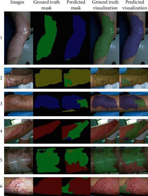
This clinical image comparison displays a series of six burn injury samples (labeled 1-6) analyzed via a deep learning segmentation network for burn depth classification. Each sample is presented in five columns: the original clinical photograph, ground truth mask, predicted mask, ground truth visualization (overlay), and predicted visualization (overlay). The images depict various anatomical regions, including limbs and torso. The segmentation uses a specific color-coding scheme: Blue represents superficial partial-thickness burns; Green indicates deep partial-thickness burns; Red denotes full-thickness burns; and Yellow signifies undebrided burn areas. Visually, superficial partial-thickness areas show mild erythema, whereas deep partial-thickness and full-thickness burns exhibit more extensive tissue damage, altered texture, and significant color variations from pale white to deep red. The figure serves as an educational tool for diagnostic radiology and dermatology, demonstrating the ability of AI to differentiate between complex burn severities and the challenges of accurately delineating transition zones between different burn depths.

This clinical series demonstrates the progression of burn severity categorized by depth and tissue involvement. (a) First-degree burn (superficial): Presents as erythema of the epidermis without blistering, consistent with a sunburn. (b) Second-degree superficial partial-thickness burn (SPTB): Displays clear blistering (bullae) and moist, red tissue, indicating damage to the papillary dermis. (c) Second-degree deep partial-thickness burn (DPTB): Shows a mottled appearance with ruptured blisters and more significant exudate, extending into the reticular dermis. (d) Third-degree burn (full-thickness): Characterized by a central area of leathery, dark eschar formation surrounded by a zone of stasis, indicating total destruction of the epidermis and dermis into the subcutaneous fat. (e) Fourth-degree burn: Illustrates the most severe injury, extending through all skin layers to involve underlying fascia, skeletal muscle (rectus abdominis), and potentially bone, appearing charred and necrotic. This visual comparison serves as an educational tool for clinical triage and the classification of thermal injuries.
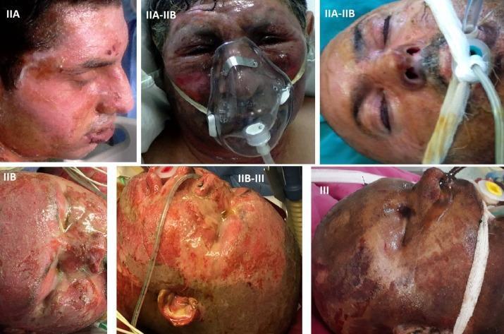
This composite of six clinical photographs illustrates the progression and varied morphology of facial burn injuries, categorized by depth and severity from Grade IIA to Grade III. Image IIA shows superficial partial-thickness burns with erythematous skin, moist texture, and minor blistering. Images IIA-IIB transition to deep partial-thickness burns, presenting with mottled red-and-white areas, significant facial edema, and periorbital swelling. Image IIB demonstrates more extensive dermal damage with less blanching. Images marked IIB-III and III showcase full-thickness burns, characterized by a leathery, charred appearance, necrotic eschar, and dark brown-to-black discoloration indicating complete destruction of the dermis and underlying appendages. The clinical context is reinforced by visible medical interventions, including oxygen masks, nasogastric tubes, and endotracheal tubes, highlighting the critical nature of airway management and supportive care in severe thermal trauma. This series serves as an educational tool for distinguishing burn depth based on color, exudate presence, and tissue texture in a clinical setting.
hypertrophic burn scar compression garment pressure therapy
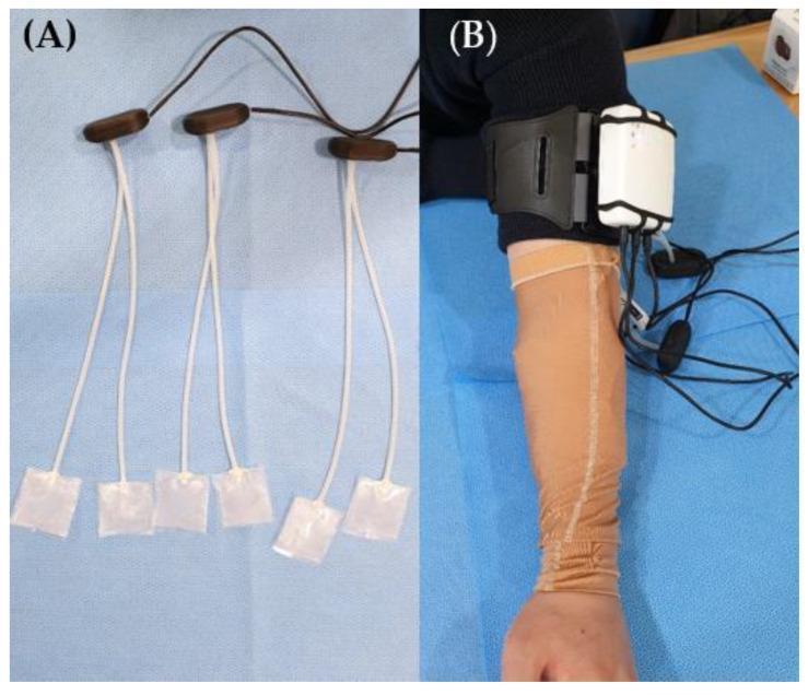
Clinical and procedural photographs illustrating a portable pressure-monitoring system used in burn scar management. Image (A) displays a detailed view of several flexible piezoresistive sensors. Each sensor consists of a square, translucent, ultra-thin pad connected by white leads to dark brown oblong hubs, which interface with a main data cable. Image (B) demonstrates the clinical application on a patient's forearm. The patient is wearing a tan-colored, tubular compression garment designed for hypertrophic scar therapy. A white, portable monitoring device is secured to the upper arm using a black adjustable strap. The sensors are placed at the interface between the compression garment and the skin to monitor the therapeutic pressure range, typically 15–25 mmHg. This setup is used in rehabilitative medicine to ensure consistent pressure application, which is critical for reducing scar thickness and improving skin elasticity during the proliferative phase of healing after burn injuries.
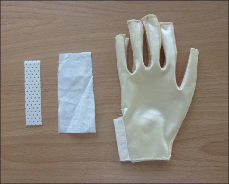
A clinical photograph displaying the components of a modified pressure garment system used in rehabilitative medicine for burn scar management and hand therapy. On a neutral background, three items are arranged horizontally: a rectangular strip of white, perforated thermoplastic material used for rigid splinting; a rectangular piece of soft, white cloth used for creating external pockets on the garment; and a cream-colored, synthetic elastane pressure glove. The glove features a distal open-finger design (open fingertips) to allow for digital circulation monitoring and sensory feedback. The garment construction includes visible seams for anatomical contouring and a lateral wrist opening secured with a hook-and-loop strap. This modified system is designed to integrate thermoplastic splints with compression therapy to prevent hypertrophic scar contractures and maintain finger extension while improving patient compliance.
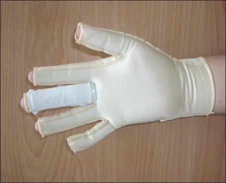
This clinical photograph displays a customized compression garment for the hand, specifically a modified pressure glove designed for burn scar management and rehabilitation. The glove is made of a light-colored, high-stretch elastic fabric with reinforced seams along the fingers and wrist. Two significant modifications are shown: first, 'open window' distal cutouts at the fingertips of all digits to allow for clinical monitoring of distal perfusion and sensation; second, an integrated dorsal pocket on the middle finger containing a shaped thermoplastic splint. This hybrid design combines the therapeutic benefits of continuous compression for scar maturation with the structural support of splinting to prevent joint contractures and maintain finger extension. The clinical focus of this visual is on hand therapy, scar management, and the integration of orthotic devices with compression therapy for improved patient compliance and functional recovery.
burn anti-deformity positioning splint occupational therapy
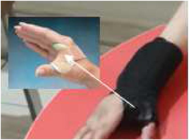
This clinical photograph displays a web spacer splint applied to a pediatric hand, an orthotic device commonly used in physical and occupational therapy for conditions like hemiplegic cerebral palsy (HCP). The splint is designed to manage thumb-in-palm deformity and spasticity by maintaining the thumb in a functional abducted position. The device consists of two primary materials: a rigid or semi-rigid light-colored thermoplastic component situated directly within the first dorsal web space to provide structural support, and a black neoprene fabric sleeve that wraps around the wrist and hand for stabilization and comfort. An inset image provides a close-up view of the thermoplastic spacer's positioning between the thumb and index finger. A white arrow points toward the base of the thumb, indicating the vector of support or the anatomical focus of the intervention. This visual illustrates a conservative management strategy for improving hand function and maintaining range of motion in patients with hypertonicity of the adductor pollicis.
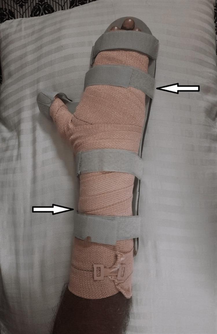
A clinical photograph of a patient's forearm and hand demonstrating a cock-up splint for the rehabilitation of a burn injury. The visual depicts a rigid dorsal support structure extending from the mid-forearm to the metacarpophalangeal joints, maintaining the wrist in a neutral or slightly extended position to prevent contracture. The limb is wrapped in a light peach-colored elastic crepe bandage that covers the forearm and hand, providing compression for edema management. The thumb is partially wrapped but remains in a functional position. The entire assembly is secured by four wide, gray hook-and-loop (Velcro) straps positioned at the proximal forearm, wrist, mid-palm, and distal phalanges. The fingertips are visible at the distal end of the splint to allow for neurovascular monitoring. This clinical application is typical for physical therapy management of second-degree (deep partial-thickness) burns to prevent deformity and maintain range of motion.
rule of nines burn total body surface area estimation
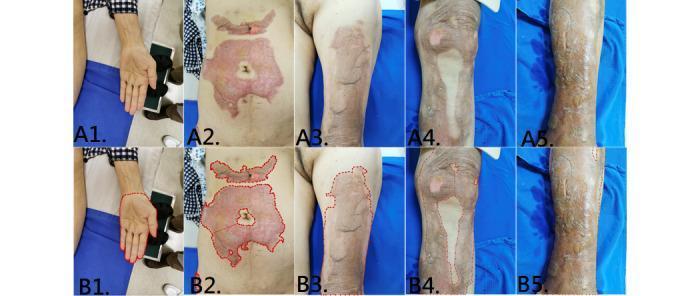
This composite of clinical photographs illustrates various burn injuries and skin lesions across multiple anatomical regions, paired with corresponding segmentation masks (B1-B5) used for Total Body Surface Area (TBSA) estimation. A1 displays a supinated left hand and palm used as an anatomical reference for sizing. A2 focuses on the abdomen, showing a large, irregularly shaped partial-thickness burn characterized by a pink-to-red erythematous base with areas of central pallor, suggesting varying burn depths. A3, A4, and A5 depict injuries on the left thigh, right leg/knee, and left lower leg, respectively. These areas exhibit extensive post-inflammatory hyperpigmentation, mottled tan-to-brown discoloration, and varying textures ranging from smooth to glossy or dry, characteristic of healing burn wounds or hypertrophic scarring. The series demonstrates the application of machine learning (Mask R-CNN) in dermatology and burn surgery to accurately delineate wound boundaries (red dashed lines in row B) for objective clinical assessment and treatment planning.
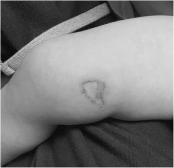
Clinical photograph of a pediatric patient (1.5 years old) showing a localized chemical burn on the medial aspect of the right thigh, superior to the knee. The lesion represents a 0.25% Total Body Surface Area (TBSA) full-thickness burn. Visually, the burn is characterized by an irregularly shaped, somewhat quadrilateral area of pale, blanched skin, indicating deep tissue damage and potential insensitivity. The borders of the wound are clearly demarcated with a slightly raised edge, but notably lack significant surrounding erythema or gross inflammation in this specific stage of presentation. The skin within the central wound exhibits textural changes consistent with full-thickness destruction of the epidermis and dermis. This image illustrates the focal, high-intensity tissue damage that can occur from accidental contact with substances such as nail adhesive, requiring careful clinical assessment of burn depth despite a small TBSA percentage.
burn contracture neck axilla anti-deformity position
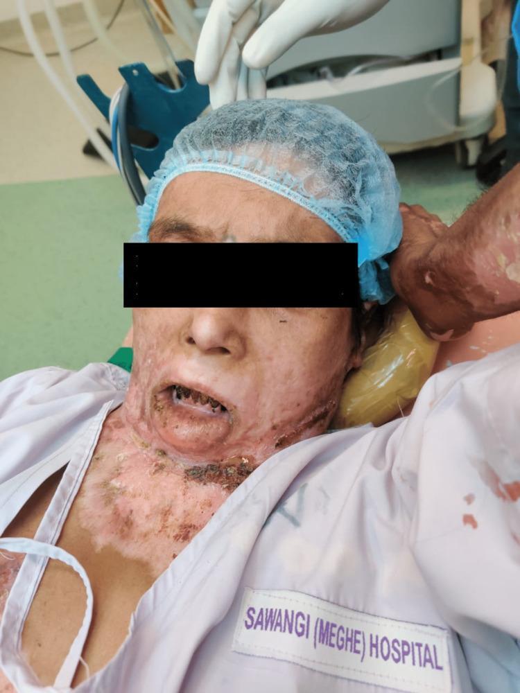
Clinical photograph of a patient in a supine position, demonstrating severe post-burn sequelae affecting the lower face, neck, and upper chest. Key clinical findings include extensive hypertrophic scarring and contracture bands extending from the submental region to the infraclavicular area. The neck contracture has resulted in a fixed flexion deformity at the atlanto-occipital joint, severely restricting cervical extension. Facial involvement is marked by microstomia (restricted mouth opening) and eversion of the lower lip (ectropion) with exposed mucosa. The skin exhibits multi-chromatic dyspigmentation, including areas of hypopigmentation, erythema, and hyperpigmented scarring, along with possible crusting or eschar near the base of the neck. The patient is shown in a perioperative or critical care setting, indicated by the surgical cap, head support, and gloved medical personnel, likely preparing for airway management or reconstructive surgery. This image serves as a significant clinical example of complex burn contractures and the associated challenges in managing difficult airways and physical rehabilitation.
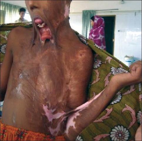
This clinical photograph displays severe, chronic post-burn complications in a pediatric or adolescent patient. The image shows extensive hypertrophic scarring and tissue contracture affecting the face, neck, and upper torso. Notable features include a severe neck contracture that has pulled the chin downward toward the chest, resulting in a marked mandibular deformity and persistent open-mouth posture (ectropion of the lower lip). The oral cavity exhibits significant distortion with dental malocclusion and a protruding tongue, likely exacerbated by soft tissue traction. The skin across the anterior chest and neck is characterized by irregular texture, areas of both hyperpigmentation and hypopigmentation (depigmentation), and dense fibrous bands. A web-like contracture is also visible in the left axillary and antecubital region, significantly restricting the range of motion. This image illustrates the long-term sequelae of inadequately managed severe burns, highlighting the critical need for early anti-contracture positioning, splinting, and surgical reconstruction in burn rehabilitation.
Occupational Therapy in Burns
Types, Recovery, Classification, Complications, and Pre/Post-Operative Management
1. TYPES OF BURNS
a. Thermal Burns
- Most common type
- Flame burns: direct contact with fire; often full-thickness; high risk of inhalation injury
- Scald burns: hot liquids (water, oil, steam); common in children and elderly; usually partial-thickness
- Contact burns: touching hot objects (stove, iron); localized; deep partial- or full-thickness
- Flash burns: brief intense heat (explosion, arc flash); typically superficial-to-partial thickness
b. Chemical Burns
- Acids (sulfuric, hydrochloric) - cause coagulative necrosis; self-limiting depth
- Alkalis (lye, cement) - cause liquefactive necrosis; penetrate deeper and are more destructive
- Hydrofluoric acid - uniquely dangerous; causes hypocalcemia, cardiac arrhythmias; treated with calcium gluconate
- Formic acid - causes hemolysis and hemoglobinuria
- Treatment: immediate irrigation with water for minimum 30 minutes; dry chemicals swept off first
- (Reference: Schwartz's Principles of Surgery)
c. Electrical Burns
- Entry and exit wound pattern; iceberg effect - surface injury underestimates deep tissue damage
- Low voltage (<1000V): household current; local injury
- High voltage (>1000V): industrial; massive deep tissue destruction, muscle necrosis, rhabdomyolysis, cardiac arrhythmia, renal failure
- Arc flash burns: intense radiant heat from electrical arc; thermal rather than true electrical injury
- Lightning burns: massive current, brief exposure; fern-like Lichtenberg figures on skin
d. Radiation Burns
- Ionizing radiation (radiation therapy, nuclear exposure)
- UV burns (sunburn) - superficial; rarely require OT intervention
- Progressive tissue damage over days-weeks after exposure
e. Friction Burns
- Abrasion-type injury (road rash, rope burns)
- Superficial to partial thickness; combined mechanical and thermal mechanism
2. CLASSIFICATION OF BURNS
A. By Depth (Dupuytren / Modified Classification)
| Degree | Old Term | Depth Involved | Clinical Features | Healing |
|---|---|---|---|---|
| Superficial (1st degree) | First-degree | Epidermis only | Erythema, pain, dry, no blisters | 3-7 days; no scarring |
| Superficial Partial-Thickness (2nd degree) | Superficial second | Epidermis + superficial dermis (papillary) | Blisters, moist, weeping, intensely painful, blanches | 10-14 days; minimal scarring |
| Deep Partial-Thickness (2nd degree) | Deep second | Into reticular dermis | Mottled pink/white, less painful (nerve ends damaged), does not blanch readily | 21-35 days; high scar risk; may need grafting |
| Full-Thickness (3rd degree) | Third-degree | All layers of dermis | Leathery, waxy/charred, painless, dry, no blanching | Does NOT heal spontaneously; requires excision and grafting |
| 4th degree | - | Extends to fat, muscle, bone | Charred, deeply necrotic | Requires amputation or flap coverage |
- Zone of Coagulation (center): most severely damaged; coagulative necrosis; requires excision
- Zone of Stasis (middle): compromised blood flow; can recover with good care or convert deeper with infection/poor perfusion
- Zone of Hyperemia (periphery): increased perfusion; heals spontaneously
B. By Size - Total Body Surface Area (TBSA)
- Head and neck: 9%
- Each upper extremity: 9%
- Anterior trunk: 18%
- Posterior trunk: 18%
- Each lower extremity: 18%
- Perineum/genitalia: 1%
C. By Severity (ABA Classification)
| Severity | Criteria |
|---|---|
| Minor | <10% TBSA partial-thickness (adult); <5% (elderly/child); <2% full-thickness; no face/hands/feet/genitalia/joints |
| Moderate | 10-20% TBSA partial-thickness (adult); 5-10% (child/elderly); 2-5% full-thickness |
| Major/Severe | >20% TBSA (adult); >10% (child/elderly); >5% full-thickness; involves face, hands, feet, genitalia; circumferential burns; inhalation injury; electrical; chemical |
3. RECOVERY PROCESS / WOUND HEALING IN BURNS
Phase 1: Inflammatory Phase (0 to 3-5 days)
- Vasodilation, increased capillary permeability → massive edema formation
- Neutrophil infiltration, then macrophages
- Release of pro-inflammatory cytokines (IL-1, IL-6, TNF-α)
- In major burns: systemic inflammatory response syndrome (SIRS), fluid shifts, distributive shock
- Fluid resuscitation is the priority (Parkland formula: 4 mL × kg × %TBSA in 24 hours)
- Wound is unstable; OT interventions limited to positioning and edema management
Phase 2: Proliferative/Fibroplasia Phase (5 days to 3 weeks)
- Fibroblast migration and collagen synthesis
- Angiogenesis (new blood vessel formation)
- Epithelialization: keratinocytes migrate from wound edges and skin appendages (hair follicles, sweat glands) - this is why deep partial-thickness burns with intact dermal appendages can still re-epithelialize
- Wound contraction: myofibroblasts pull wound edges together - beneficial for closure, but if over-exuberant causes contracture
- Risk of hypertrophic scar formation is highest during this phase
- Skin grafting is performed during this phase for deep partial-thickness and full-thickness burns
Phase 3: Remodeling Phase (3 weeks to 2+ years)
- Collagen cross-linking and reorganization
- Scar matures - initially raised, red, firm → gradually softens, flattens, pales
- If collagen overproduction persists beyond normal limits: hypertrophic scar or keloid
- This is the primary phase for scar management and OT rehabilitation
4. POST-BURN COMPLICATIONS
A. Contractures
- Wound contraction by myofibroblasts during healing
- Scar contracture from dense, inelastic collagen bands bridging across joints
- Factors: burn depth, location over joints, inadequate positioning and splinting, patient non-compliance
- Shoulder (most common) > Elbow > Wrist > Ankle > Knee
- Linear contracture: band-like scar across joint; limits motion in one plane
- Web contracture: axilla, first web space, neck, popliteal fossa
- Circumferential contracture: complete encirclement; most functionally limiting
- Prevention (primary goal): anti-deformity positioning, splinting, pressure garments, ROM exercises
- Non-surgical: serial casting, dynamic splinting, ultrasound to increase tissue extensibility before stretching
- Surgical: Z-plasty (most common - releases and lengthens scar band), W-plasty, skin grafting, local flaps, free tissue transfer
- Post-surgical OT: immediate resumption of positioning and exercise once graft is stable; splinting at night and during activities
B. Heterotopic Ossification (HO)
-
30% TBSA burn
- Arm burns and arm grafts
- Prolonged ventilator days
- Multiple trips to the operating room
- Decreased range of motion (often the first sign)
- Pain
- Swelling over affected joint
- Warmth and erythema
- Radiograph shows ectopic bone formation (appears 3-12 weeks after injury)
- Aggressive physiotherapy (including OT) - the primary intervention
- NSAIDs (indomethacin) - inhibit prostaglandin-mediated bone formation
- Bisphosphonates (etidronate) - inhibit osteoid mineralization
- Radiation therapy - used preventively post-surgery
- Surgical excision - reserved for established, mature HO causing functional limitation; performed after bone maturation (typically 12-18 months post-injury)
- Monitor ROM closely for early signs of HO
- Gentle but consistent ROM exercises - avoid aggressive forced stretching which may accelerate HO
- Splinting to maintain functional position
- Post-surgical excision: resume ROM exercises and positioning under surgical guidance
C. Hypertrophic Scarring
- Increased inflammatory response
- Irregular neovascularization
- Aberrant cytokine and Toll-like receptor expression
- Abundant collagen production with abnormal extracellular matrix structure
- Raised, red/pink, firm
- Pruritus (itch) - often the most distressing symptom
- Pain
- Thickened, tight skin
- Restricted ROM if over joints
- Vascularity (0-3): normal to purple
- Pigmentation (0-3): normal to hypopigmented
- Pliability (0-5): normal to contracture
- Height (0-3): flat to >5mm raised
-
Pressure Therapy (cornerstone of non-surgical management):
- Custom-fitted pressure garments (Jobst, Tubigrip) delivering 15-25 mmHg of pressure
- Must be worn 23 hours/day for 12-24 months until scar matures
- Thought to cause hypoxia of scar tissue, reducing fibroblast activity; also provides mechanical reorganization of collagen fibers
- Debate continues about efficacy, but patients report comfort and reduced pruritus (Schwartz's Surgery)
-
Silicone Gel Sheeting/Pads:
- Applied directly over scar for 12-24 hours/day
- Mechanism: hydration, temperature increase, occlusion - modulates fibroblast activity
- Particularly effective in reducing pruritus, scar height, and redness
-
Scar Massage:
- Firm circular friction applied with neutral oil or silicone cream
- Performed for 5-10 minutes, 2-3 times per day
- Desensitizes hypersensitive scar, improves pliability, reduces pruritus
-
Corticosteroid Injection (medical/surgical):
- Intralesional triamcinolone injections
- Reduces collagen production and inflammatory response
-
Laser Therapy (Schwartz's Surgery):
- Pulsed Dye Laser (PDL): photothermolysis of hemoglobin; obliterates capillaries; reduces redness and vascularity
- Ablative CO2 Laser: ablates microscopic columns of tissue; stimulates matrix metalloproteinases; improves pliability, appearance, neuropathic pain, and pruritus
- General recommendation: begin at 6-12 months post-injury; ~3 treatment sessions
-
Surgical Revision (when conservative fails):
- Scar excision with split-thickness skin graft (STSG) or full-thickness skin graft (FTSG)
- Z-plasty, W-plasty for linear scars
D. Cosmetic Disfigurement
- Dyspigmentation: hypopigmentation (more common in darker skin) or hyperpigmentation
- Scarring: hypertrophic or atrophic scars, abnormal texture
- Distortion of features: ectropion (eversion of eyelids/lips), microstomia (restricted mouth opening), alopecia (hair loss), ear deformity, nasal deformity
- Contracture bands: visible deforming cords across neck, face, axilla
- Depression: documented in 4-54% of burn patients; persists in up to 43% at 2 years
- Post-Traumatic Stress Disorder (PTSD)
- Body image disturbance
- Social anxiety, withdrawal, avoidance of public
- Occupational/role disruption
- Facial orthoses/conformers: transparent face masks or thermoplastic facial splints to apply pressure and maintain contour over facial scars
- Ear conformers: thermoplastic or silicone inserts to preserve ear shape
- Mouth opening exercises: for microstomia prevention - dynamic mouth-stretching splints (microstomia prevention appliance - MPA)
- Psychosocial support (references: Creek & Lougher; Early; Bruce & Borg):
- Role of OT is to use meaningful occupation to facilitate identity reconstruction and social re-engagement
- Cognitive behavioral approaches to address fear-avoidance and negative body image
- Social skills training and supported community re-entry
- Peer support groups facilitation
- Graded community reintegration: shopping, public transport, workplace visits, etc.
- Cosmetic camouflage training: teaching application of cover-up makeup for residual discoloration
- Assistive technology: for facial disfigurement affecting communication or vision
5. PRE-OPERATIVE OT MANAGEMENT
- Planned elective surgery (scar revision, contracture release) - when patient is medically stable
- Preparation prior to acute surgical intervention (skin grafting in the early post-burn period)
Goals:
- Maximize pre-operative ROM and strength
- Prevent or minimize complications before surgery
- Educate patient about surgical procedure, expected precautions, and recovery
Interventions:
| Body Region | Deformity Tendency | Anti-Deformity Position |
|---|---|---|
| Neck | Flexion | Neck extension; foam collar or thermoplastic cervical collar |
| Shoulder | Adduction, internal rotation | 90-100° abduction; slight horizontal abduction; neutral rotation |
| Axilla | Adduction | Shoulder abduction 90° minimum; foam wedge/airplane splint |
| Elbow | Flexion | Extension; elbow extension splint |
| Wrist | Flexion | 20-30° extension; cock-up splint |
| Hand/Fingers (dorsal burn) | MCP extension; IP flexion | Anti-deformity/safe position: MCP 70-90° flexion; IPs 0°; thumb abducted (intrinsic-plus position) |
| Hand/Fingers (volar burn) | MCP flexion; IP extension | Opposite: MCPs in mild flexion; IPs extended |
| Hip | Flexion, adduction | Extension, abduction |
| Knee | Flexion | Extension |
| Ankle/Foot | Plantar flexion | Dorsiflexion 0° (neutral); foot-drop splint |
- Active ROM exercises through all available range - continued multiple times daily
- Active-assisted ROM where needed
- Passive ROM only under therapist supervision; avoid aggressive passive stretching in inflamed tissue
- Ambulation and functional mobility
- Elevation above heart level
- Compressive wrapping (within wound care protocols)
- Active muscle pumping exercises
- Maintain as much ADL independence as possible - prevents learned helplessness
- Adaptive equipment provided for self-care tasks
- Burn precautions, positioning importance
- Skin care for healed areas (moisture, sun protection)
- Realistic goal-setting for surgery outcomes
- Splint wearing schedules and exercise home program
- Therapeutic use of occupation to maintain meaningful engagement
- Addressing anxiety about surgery and appearance
- Reference: Bruce & Borg (Frames of Reference in Psychosocial OT), Early
6. POST-OPERATIVE OT MANAGEMENT
A. Immediate Post-Operative Phase (Day 3-7)
- Strict positioning to avoid graft shearing or disruption
- Immobilization splint applied over graft site - positions joint to minimize tension on graft
- Anti-deformity positioning of all non-operated areas continues
- Donor site care (often managed by nursing but OT monitors)
- Elevation maintained
- Observation for developing compartment syndrome signs
- Shoulder, neck, trunk, and uninvolved limbs remain active to prevent deconditioning
B. Graft Mobilization Phase (Week 1-3)
- Gentle active ROM exercises of grafted joints begin
- Progress from active-assisted → active → resisted
- Graft must be observed at every session - blebs, blistering, or color change reported immediately
- Splints transitioned from constant wear to wear between exercise sessions and at night
- Dynamic splints introduced if contracture tendency present
- As soon as graft is fully epithelialized (typically 2-3 weeks post-op): scar massage, silicone gel
- Custom pressure garments fitted as soon as wound can tolerate - a full garment typically fitted at 3-4 weeks post-op
- Graded return to self-care tasks
- Adaptive equipment as needed
- Energy conservation for patients with large TBSA burns (significant metabolic demands of healing)
C. Rehabilitation Phase (Weeks 3-12)
- Pressure garments worn 23 hours/day - reviewed and replaced every 2-3 months as scar changes
- Silicone inserts under pressure garments for bony prominences and concavities (web spaces, palm arch, nose)
- Scar massage multiple times daily
- Ongoing ROM to counteract scar contraction
- Putty exercises, resistive bands, progressive weights
- Functional strengthening through purposeful activity
- Skin grafts have altered sensation; sensory re-education important especially for hand grafts
- Desensitization program for hypersensitive new skin
- Full ADL retraining: dressing (particularly if axilla/shoulder involved), bathing, cooking, driving
- Work simulation and job-specific tasks
- Recreational activities
- Ongoing splinting for contracture prevention and correction
- Transition from rigid to softer, more cosmetically acceptable splints where possible
D. Long-Term / Community Phase (3+ months)
- Continued for up to 12-24 months; replaced every 2-3 months
- Patient compliance is the biggest challenge; OT role in education and motivation is key
- Facial mask (transparent thermoplastic) for facial burns
- Ear conformers
- Cosmetic camouflage application training
- Hair prosthesis fitting referral if alopecia present
- Graded community re-entry (shops, social settings, workplace)
- Return to work/school program
- Support groups for burn survivors
- Ongoing psychological support: CBT for PTSD/body image issues, mindfulness, peer mentoring
- Leisure activity reintegration
- Addressing impact on relationships and social roles
- School re-entry program - OT liaises with school to educate peers, address bullying, modify tasks
- Play and developmentally appropriate activities as therapeutic medium
- Family education and support - parents as active rehabilitation partners
- Growth monitoring - pressure garments must be adjusted frequently as child grows
- Serial splinting especially important - growth can exacerbate contractures
Summary: OT Phase-by-Phase in Burns
| Phase | Timing | Primary OT Goals | Key Interventions |
|---|---|---|---|
| Acute/Pre-Op | Day 0 - Surgery | Prevent deformity; edema control; maintain ROM | Anti-deformity splinting, positioning, active ROM, elevation, patient education |
| Post-Op Immobilization | Day 1-5 | Graft protection; prevent deconditioning | Protective splint; ROM of uninvolved joints; edema management |
| Mobilization | Day 5 - Week 3 | Restore ROM; begin scar management | Active ROM exercises, scar massage initiation, ADL retraining, pressure garment fitting |
| Rehabilitation | Weeks 3-12 | Restore function; manage scars | Full scar program, progressive strengthening, ADL, work simulation |
| Community Reintegration | 3 months+ | Return to roles; manage late complications | Pressure garments, cosmetic rehab, psychosocial support, work/school re-entry |
- Pedretti's Occupational Therapy: Practice Skills for Physical Dysfunction, Pendleton & Schultz-Krohn
- Occupational Therapy for Physical Dysfunction, Radomski & Trombly
- Occupational Therapy and Physical Dysfunction, Turner, Foster & Johnson
- Willard & Spackman's Occupational Therapy
- Schwartz's Principles of Surgery (11th ed.) - Burn Depth, Late Complications: Hypertrophic Scar, Contractures and HO; Psychological Recovery
- Occupational Therapy and Mental Health, Creek & Lougher
- Mental Health Concepts for the OTA, Early
- Frames of Reference in Psychosocial OT, Bruce & Borg
- OT for Children, Case-Smith; Frames of Reference for Pediatric OT, Kramer & Hinojosa
C. Cardiothoracic Surgery. Review of Cardiothoracic surgical, procedures, Pre operative and post operative O.T. Management Recommended book(s) for Reference: 1. Pedretti’s Practice skills for physical dysfunction edited by Heidi McHugh Pendleton ,Winifred Schultz Krohn 2. Occupational Therapy for Physical Dysfunction by Mary Vining Radomski, Catherine A Trombly 3. Occupational Therapy and Physical Dysfunction, Principles, Skills and Practice by Ann Turner, Margaret Foster, Sybil E Johnson 4. Introduction to Occupational Therapy by Hussey Subonis ,Chafea O Brien 5. Occupational Therapy and Mental Health edited by Jennifer Creek, Lesley Lougher 6. Mental Health Concepts and Techniques for the Occupational Therapy Assistant by Mary Beth Early 7. Frames of Reference in Psychosocial Occupational Therapy by Mary Ann Bruce, Barbara Borg 8. Willard & Spackman’s Occupational Therapy 9. Occupational Therapy for children by Jane Case Smith 10. Frames of Reference for Pediatric Occupational Therapy by Paula Kramer , Jim Hinojosa
coronary artery bypass graft CABG cardiac surgery sternotomy
A high-detail intraoperative clinical photograph documenting a coronary artery bypass graft (CABG) procedure. The surgical field displays a median sternotomy with the heart exposed and positioned for distal anastomosis. The central focus is the exposure and manipulation of the diagonal artery using fine surgical forceps. Multiple gloved hands are visible, coordinating the retraction of the epicardium and the stabilization of the target vessel. Cardiopulmonary bypass (CPB) is active, indicated by the presence of large-bore arterial and venous cannulae (red and orange tubing) and a sternal retractor labeled with medical instrumentation branding. Visible anatomical structures include the epicardial surface of the heart, coronary vasculature, and surrounding mediastinal tissues. The use of gauze sponges and fine sutures is evident, facilitating a clear operative field for precise vascular microsurgery. This image serves as an educational resource for cardiac surgery, demonstrating vessel exposure techniques and the configuration of the surgical field during complex bypass maneuvers.
A close-up clinical photograph of an intraoperative field during a coronary artery bypass graft (CABG) surgery. The image shows a median sternotomy with the heart exposed and stabilized by a sternal retractor. The epicardial surface of the heart is visible, notably characterized by significant yellowish epicardial adipose tissue. Surgeons in sterile gloves use fine surgical forceps to isolate and stabilize the left anterior descending (LAD) artery for anastomosis. A harvested conduit, identified as the right internal mammary artery (RIMA), is being positioned toward the patient's head to facilitate the distal anastomosis. Surrounding the cardiac structures are blood-stained surgical drapes, gauze sponges, and specialized cardiothoracic retractors (Medtronic). The image illustrates the complex surgical positioning required for revascularization in a patient with dextrocardia and situs inversus, emphasizing the technical precision needed for arterial tunneling and suturing in a reversed anatomical orientation.
An intraoperative clinical photograph showing a median sternotomy field during Coronary Artery Bypass Graft (CABG) surgery. The thoracic cavity is held open by a metallic Medtronic sternal retractor. Centrally, the human heart is visible, covered partially by epicardial adipose tissue (yellowish in appearance). The primary focus is the ascending aorta, where two saphenous vein grafts have been successfully anastomosed. These proximal anastomoses are secured with fine black sutures visible at the connection points between the tubular vein conduits and the aortic wall. The surgical field includes green and blue sterile drapes, surgical sponges, and several black stay sutures used for tissue retraction. The red, well-perfused myocardium and surrounding tissues indicate active circulation, consistent with the post-cross-clamp phase of the procedure. This image serves as an educational reference for cardiac surgical anatomy, proximal anastomosis techniques in revascularization, and the use of sternal retraction in open-heart surgery.
cardiac rehabilitation phases activity progression heart surgery
This diagnostic image is a 12-lead electrocardiogram (EKG) comparison chart from a stress echocardiogram procedure. The visual layout presents a side-by-side comparison of cardiac electrical activity at two distinct phases: 'Baseline' (left) recorded at 95 bpm, and 'Max ST' during Exercise Stage 1 (right) recorded at 142 bpm. The EKG focuses on precordial leads (V1-V6) and limb leads (I, II, III, aVR, aVL, aVF). Key visual findings at baseline include a blunted R-wave progression from V1 to V3, characterized by small R-wave amplitudes followed by deeper S-waves. Under exercise stress (MAX ST), the image demonstrates morphology changes in the ST segments and T-waves, specifically upright T-waves and shifts in the ST-segment slope measured at 60ms post-J point. The chart includes quantitative annotations for ST-segment deviation (mm) and slope (mV/s) beneath each lead label. This visual serves as an educational tool for assessing exercise-induced ischemic changes, evaluating R-wave progression, and monitoring heart rate response during cardiac stress testing.
A clinical photograph depicting a postoperative patient engaged in a walker-assisted gait training session as part of a phase I cardiac rehabilitation program. The patient, shown from a rear perspective, is utilizing a standard height-adjustable silver metal walker with non-slip rubber tips. The patient is wearing protective medical attire, including a pink surgical cap, a patterned hospital gown, and a blue protective isolation gown, indicating adherence to infection control protocols following a heart transplant and midline sternotomy. The lower extremities are visible, demonstrating weight-bearing ambulation on postoperative day 28. A physical therapist or healthcare provider is seen in the background in a crouched position, providing supervision and ensuring patient safety during the mobility assessment. The clinical setting is a hospital general ward or rehabilitation area, containing medical equipment such as a tilt table and monitoring stands. This visual documents a milestone in the functional recovery and physical therapy progression after complex thoracic surgery.
heart valve replacement surgery types mitral aortic
This composite figure illustrates the procedural results of combined transcatheter aortic valve replacement (TAVI) and transcatheter edge-to-edge repair (TEER) of the mitral valve. Panels A and B display 3D transesophageal echocardiography (TEE) reconstructions showing the mitral valve in a surgical 'en face' view, revealing the dual-orifice morphology created by the placement of a central clip (MVC-IIIf) between the A2 and P2 leaflets. Panel C provides a quantitative planimetric analysis of the mitral valve area, showing two distinct orifices measuring 2.04 cm² and 1.31 cm² post-repair. Panel D features a color Doppler TEE image assessing hemodynamic status; it demonstrates the resolution of mitral regurgitation and shows mild residual paravalvular regurgitation at the aortic position. Panels E and F provide reference illustrations of the specific medical devices used: a J-Valve transcatheter heart valve and the MVC-IIIf mitral valve clip. This content serves to demonstrate advanced structural heart interventions and post-procedural imaging assessment for cardiology and cardiothoracic surgery education.
This composite of two intraoperative clinical photographs illustrates the surgical implantation of Edwards Sapien 3 transcatheter valves in both mitral and aortic positions. The left image provides a subvalvular view from the left ventricle, demonstrating a 29 mm Sapien 3 valve deployed in the native mitral annulus (SITRAL technique). The valve's characteristic cobalt-chromium hexagonal frame is visible through cardiac tissue, with a yellow surgical probe positioned nearby. The right image shows an intraoperative view through an aortotomy, revealing a second Sapien 3 valve secured in the aortic position. The aortic walls are retracted, showing the valve leaflets and the surrounding tissue of the aortic root. These images demonstrate a complex double-valve replacement strategy utilized in a patient with severe mitral annular calcification (MAC) and aortic stenosis. The educational focus is on the direct surgical placement of balloon-expandable transcatheter heart valves (THVs) during open-heart surgery as an alternative to conventional valve replacement in high-risk anatomical scenarios.
lung surgery thoracotomy incision types VATS minimally invasive
This clinical photograph displays the surgical field of a Video-Assisted Thoracoscopic Surgery (VATS) for spinal vertebral body tethering. The thoracic region of a patient in a lateral decubitus position is shown, prepped with an adhesive incise drape. A central mini-thoracotomy incision (approximately 5 cm) is held open by a self-retaining muscle-sparing retractor. Surrounding the primary incision are multiple surgical ports: three 5-mm trocars are placed along the anterior axillary line to facilitate instrumentation, and one larger 10-mm port is positioned medially for a 30-degree thoracoscopic camera. The strategic arrangement of these ports between the fourth and eighth intercostal spaces allows for multi-level access to the thoracic spine. A surgeon's gloved hand is visible in the upper right quadrant, and a single surgical instrument is seen entering a port site. This setup illustrates the hybrid approach combining direct visualization through a small incision with thoracoscopic assistance for minimally invasive orthopedic spinal correction.
This clinical photograph captures an intraoperative view of a minimally invasive thoracic procedure, specifically a uniportal video-assisted thoracoscopic surgery (VATS). The image shows multiple long, slender surgical instruments, including a thoracoscope, grasping forceps, and a curved suction-irrigation device, simultaneously inserted through a single small utility incision in the lateral chest wall, typically at the 5th intercostal space. Gloved surgeons are seen manipulating these instruments to access the hilar structures of the lung. A sterile field is maintained with green surgical drapes and a clear plastic sleeve covering the thoracoscope cable. The educational focus of the image is the technical challenge of instrument triangulation and coordination required when performing major lung resections through a single-port approach, emphasizing the use of specialized long and curved instrumentation to maintain adequate visualization and exposure of the pulmonary parenchyma and hilar anatomy.
Occupational Therapy in Cardiothoracic Surgery
Review of Procedures, Pre-Operative and Post-Operative OT Management
1. OVERVIEW: ROLE OF OT IN CARDIOTHORACIC CONDITIONS
- Activity tolerance and graded exercise (metabolic equivalents - METs)
- Energy conservation and work simplification
- Sternal and thoracic precautions compliance
- Psychosocial adjustment to life-threatening illness and major surgery
- ADL re-training with cardiac/pulmonary monitoring
- Breathing and airway clearance education (in conjunction with physiotherapy)
- Return to occupational roles
2. REVIEW OF CARDIOTHORACIC SURGICAL PROCEDURES
A. Cardiac Surgical Procedures
1. Coronary Artery Bypass Grafting (CABG)
- Internal Mammary Artery (IMA) / Internal Thoracic Artery: preferred conduit - left IMA to LAD is the gold standard (excellent long-term patency)
- Saphenous Vein Graft (SVG): from leg; used for multiple-vessel disease
- Radial Artery Graft: second arterial conduit for complex disease
- Median sternotomy: standard; sternal retractor provides access to pericardium and heart
- Off-pump CABG (OPCAB): heart beating, no cardiopulmonary bypass (CPB) - reduces neurological complications
- Minimally invasive CABG (MIDCAB): small left thoracotomy; usually for isolated LAD disease
- Median sternotomy → sternal precautions are the cornerstone of OT management
- Saphenous vein harvest → leg wound, possible lower limb edema and mobility limitations
- Radial artery harvest → upper limb wound, potential hand vascular compromise
2. Valve Surgery
- Aortic Valve Replacement (AVR): for aortic stenosis (most common indication) or regurgitation
- Mechanical valves (lifelong anticoagulation) vs. bioprosthetic (limited durability, no anticoagulation)
- TAVI/TAVR (Transcatheter Aortic Valve Replacement): minimally invasive; catheter-based; for high-risk surgical patients - shorter recovery, no sternotomy in some approaches
- Mitral Valve Repair (preferred when feasible) or Mitral Valve Replacement (MVR)
- For mitral stenosis (usually rheumatic), mitral regurgitation (degenerative, ischemic, functional)
- Approached via median sternotomy + right or left atriotomy, or minimally invasive thoracotomy
- Tricuspid repair (annuloplasty) commonly done at time of left-sided valve surgery
- Right-sided valve surgery for infective endocarditis, carcinoid, congenital defects
- Post-valve surgery patients often have a history of long-standing heart failure with reduced functional capacity
- Activity grading must account for pre-operative deconditioning
- Anticoagulation requires education and activity precautions
3. Heart Transplantation
- For end-stage heart failure refractory to medical therapy
- Orthotopic heart transplant (OHT): diseased heart removed, donor heart implanted
- Bilateral sequential or en-bloc lung transplant may accompany (heart-lung transplant)
- Post-transplant: immunosuppression, rejection monitoring, infection risk
- Denervated transplanted heart has altered physiological responses - heart rate rise is delayed on exertion; RPE (Rating of Perceived Exertion) more reliable than heart rate for exercise monitoring
4. Congenital Heart Surgery
- Atrial/ventricular septal defect (ASD/VSD) closure
- Tetralogy of Fallot repair
- Fontan procedure, arterial switch operation (for transposition)
- Pediatric OT considerations are critical (Case-Smith; Kramer & Hinojosa)
5. Ventricular Assist Device (VAD) / LVAD Implantation
- Mechanical circulatory support for advanced heart failure
- Bridge to transplant or destination therapy
- External drive line exits skin → infection risk; activity limitations
- OT: ADL retraining with device in situ, drive line care education, activity pacing
6. Pericardial Surgery
- Pericardiectomy: for constrictive pericarditis
- Pericardial window: for malignant or recurrent pericardial effusion
B. Thoracic Surgical Procedures
1. Lung Resections
- Pneumonectomy: removal of entire lung; most physiologically demanding
- Lobectomy: removal of a lobe; most common resection for lung cancer
- Segmentectomy / Wedge resection: parenchyma-sparing; for small peripheral lesions or poor candidates for major resection
- Sleeve resection: removes bronchial segment + lobe; preserves lung tissue when central tumor involves bronchus
- Thoracotomy (posterolateral): standard open approach; divides chest muscles + spreads ribs → significant post-operative pain and shoulder restriction
- Video-Assisted Thoracoscopic Surgery (VATS): 2-4 small port incisions; less pain, faster recovery, better lung function preservation
- Robotic-assisted thoracoscopic surgery (RATS): enhanced visualization, surgeon console control
- Post-thoracotomy: ipsilateral shoulder restriction, incisional pain, reduced chest expansion
- Reduced pulmonary reserve after resection limits activity tolerance
- Energy conservation training is essential
2. Lung Transplantation
- Single lung transplant (SLT): for COPD, pulmonary fibrosis
- Bilateral sequential lung transplant (BSLT/DSSLT): for cystic fibrosis, bronchiectasis, pulmonary hypertension
- Post-transplant: immunosuppression, rejection (acute/chronic), infections, bronchiolitis obliterans syndrome (BOS)
- Rehabilitation: gradually progressive exercise; education about immunosuppression precautions in daily life
3. Esophageal Surgery
- Esophagectomy: for esophageal cancer; Ivor-Lewis or McKeown procedure
- Combined thoracic and abdominal incisions
- Post-operative: gastric conduit reconstruction, feeding management, reflux precautions
- OT: upright positioning post-meals, adapted feeding techniques, nutrition management education
4. Mediastinal Surgery
- Thymectomy (for myasthenia gravis, thymoma)
- Mediastinal mass excision
- Typically via sternotomy or VATS
3. PRE-OPERATIVE OT MANAGEMENT
A. Pre-Operative Assessment
- Prior functional level: ADL independence, work roles, leisure
- Exercise tolerance and symptom-limited activity level
- Home environment: stairs, bathroom setup, caregiver availability
- Social support system
- Psychological readiness and coping style
- MET (Metabolic Equivalent of Task) estimation: 1 MET = oxygen uptake at rest (3.5 mL/kg/min)
- Patients who cannot achieve 4 METs have higher perioperative risk
- ADL activities and MET equivalents (see table below)
- 6-Minute Walk Test (6MWT): objective measure of functional exercise capacity
- Dyspnea scales: Modified Borg Dyspnea Scale, Modified Medical Research Council (mMRC)
- Hand grip strength: predictor of surgical outcomes and mortality (Braunwald's Heart Disease)
- Frailty assessment (particularly in elderly cardiac patients)
- Anxiety and depression screening (PHQ-9, GAD-7)
- Understanding of diagnosis and surgical procedure
- Social support and home circumstances
- History of cardiac anxiety or illness behavior
B. Pre-Operative Education
| Restriction | Standard Precaution | Duration |
|---|---|---|
| No pushing with arms | No pushing up from chair with hands | 6-8 weeks |
| No pulling | No pulling open heavy doors, pulling laundry | 6-8 weeks |
| No lifting | Nothing >2-5 kg (varies by surgeon) | 6-8 weeks |
| No reaching behind back | No reaching to back of car | 6-8 weeks |
| No bilateral shoulder elevation above 90° | No overhead reaching with both arms | 6-8 weeks |
| No log-rolling or twisting | Turn whole body as one unit | 6-8 weeks |
- Incentive spirometry: patient inhales slowly and deeply to maximize lung volume - starts pre-operatively as practice
- Diaphragmatic breathing: relaxed, controlled diaphragmatic expansion
- Active cycle of breathing technique (ACBT): breathing control → thoracic expansion exercises → forced expiration/huff → cough
- Pillow splinting (hugging): patient holds pillow firmly against sternum/chest wall when coughing - protects sternal wound from the mechanical stress of coughing
- Rating of Perceived Exertion (RPE) - Borg scale 6-20 (target: 11-14 in early recovery)
- Symptoms to watch for: chest pain, excessive dyspnea, palpitations, dizziness, lightheadedness
- Pulse monitoring (if self-monitoring prescribed)
- Raised toilet seat (prevents straining and pushing up with arms)
- Shower chair
- Grab bars
- Long-handled reaching and dressing aids (to avoid bending)
- Reacher, sock aid, long-handled shoe horn (to reduce bending and breath-holding)
- Firm chair with armrests (to minimize push-up from chair)
- Pre-operatively arrange frequently used items at waist height (no overhead or floor level reaching)
- Set up a sleeping area on the ground floor if needed (initially)
- Plan meals and domestic chores in advance; arrange caregiver support
- Address surgical anxiety (common in cardiac patients)
- Goal-setting: realistic recovery timeline
- Pain management expectations
- Reference: Bruce & Borg (psychosocial frames of reference); Creek & Lougher (occupational therapy and mental health)
4. POST-OPERATIVE OT MANAGEMENT
A. Acute Phase - ICU / Ward (Days 1-7)
- Heart rate (HR): should not exceed 20-30 bpm above resting
- Blood pressure (BP): systolic should not drop >10 mmHg or rise excessively
- O2 saturation (SpO2): should stay ≥94-95%
- Rating of Perceived Exertion (RPE): Borg 11-13 ("fairly light to somewhat hard")
- Watch for: angina, excessive dyspnea, diaphoresis, pallor, arrhythmia
- Semi-reclined to upright in bed as tolerated - reduces cardiac preload, improves diaphragmatic excursion
- Leg elevation for saphenous vein harvest site edema
- Avoidance of Valsalva maneuver (breath-holding during exertion) - increases intrathoracic pressure, may dislodge sternal sutures
- Log-rolling technique: turning in bed as a unit without twisting the torso
- Sit-to-stand technique: feet flat on floor, lean forward, stand using leg strength - NOT pushing up with arms on armrests (sternal precaution)
- Safety with all transfers - orthostatic hypotension is common post-operatively
- Day 1-2: sitting at edge of bed, standing
- Day 2-3: walking short distances in ward
- Progressive increase as tolerated
- Associated with reduced pulmonary complications, deep vein thrombosis, delirium, and length of stay
- Washing and dressing: from seated position, using adaptive equipment; within sternal precautions
- Upper limb dressing: loose front-fastening garments initially
- Foot/lower leg: long-handled shoe horn, sock aid - reduces bending and breath-holding
- Toileting: raised toilet seat to reduce push-up strain; avoid Valsalva during defecation
- Feeding: usually independent early; monitor dyspnea with eating
- Reinforce incentive spirometry
- Pillow splinting for coughing - patient holds pillow against sternum
- ACBT for secretion clearance
B. Phase II - Acute Rehabilitation / Inpatient Ward (Days 5-14)
| METs | Activity Examples | When Introduced (approx.) |
|---|---|---|
| 1-2 METs | Lying, sitting, self-care seated, slow walking on flat | Days 1-3 |
| 2-3 METs | Showering seated, slow walking, light housework seated, dressing | Days 3-7 |
| 3-4 METs | Walking at moderate pace, light cooking, grooming standing, climbing one flight of stairs | Week 2 |
| 4-5 METs | Brisk walking, gardening (light), vacuuming, driving (if cleared) | Week 3-4 |
| 5-7 METs | Cycling, social sports, moderate housework | Week 6+ |
| >7 METs | Vigorous sport, heavy manual work | Week 8-12+ (surgical clearance required) |
- Dressing: avoid pulling garments over head (initially); no reaching behind back; front-fastening garments
- Bathing: no gripping bath sides to get in/out; shower chair if needed; handheld shower
- Grooming: avoid bilateral overhead arm elevation (e.g., blowdrying hair)
- Meals preparation: lightweight pots, seated cooking, electric rather than manual appliances
- Laundry: no wringing; front-loading machines at waist height preferred
- Getting in/out of car: log-roll technique to enter; support steering wheel when braking initially; no driving for 4-6 weeks typically
- Sexual activity: patient education - when to resume (typically 4-6 weeks post-op, patient-initiating position); avoid positions requiring arm weight-bearing
- Pace: slow down; avoid rushing; take rest breaks between tasks
- Plan: organize tasks to minimize effort; batch similar tasks; arrange environment
- Prioritize: identify essential vs. non-essential tasks; delegate where possible
- Position: seated work reduces energy expenditure by 25% compared to standing
- Sit to cook, iron, groom
- Keep frequently used items at waist height (no bending or reaching overhead)
- Use lightweight equipment (electric tin opener, push-button appliances)
- Shop online; use wheeled trolley for carrying
- Rest for 10-20 minutes before and after demanding tasks
- Breathe with exertion - exhale during the effort, never hold breath
- Exhale on effort (lifting, pushing, rising from chair)
- Never perform Valsalva maneuver
- Pursed lip breathing for dyspnea management during activity
- Gentle active shoulder range of motion (AROM) exercises within pain-free range
- Elbow, wrist, hand exercises freely
- Progressive shoulder elevation - avoid bilateral simultaneous elevation above 90° during early weeks
- Following thoracotomy (not sternotomy): ipsilateral shoulder pendulum exercises, progressive ROM to prevent shoulder stiffness and frozen shoulder
- Positioning for pain relief
- Heat/cold (as appropriate and cleared)
- Splinting posture education to reduce postural pain
- Breathing techniques to minimize incisional pain during movement
C. Phase III - Outpatient/Community Cardiac Rehabilitation
- Phase I (inpatient): early mobilization, education, functional activities - OT primary role
- Phase II (outpatient, supervised): structured exercise, education program, risk factor modification - OT contributes ADL retraining, work simulation, psychosocial support
- Phase III (community, unsupervised maintenance): patient self-manages with knowledge from earlier phases
- Repeat 6MWT, grip strength, MET estimation
- Reassess ADL performance and identify remaining barriers
- Progressive withdrawal of adaptive equipment as function returns
- Job demands analysis: physical, cognitive, and environmental demands
- Graded return-to-work plan
- Worksite modification recommendations
- Heavy manual work: may require cardiology/surgical clearance for specific MET demands
- Varies by country and procedure
- CABG/valve surgery: typically 4-6 weeks post-op (medical clearance)
- Visual, cognitive, and reaction time assessment if concerns
- Vehicle modifications for early recovery (extended mirrors, automatic transmission)
- Addressed by OT or cardiac nurse as part of lifestyle education
- Generally 4-6 weeks post-op; guided by symptom level (if can climb two flights of stairs without symptoms, sexual activity is typically safe)
- Positioning advice for sternal protection
- Depression: highly prevalent (20-40%) post-cardiac surgery; associated with worse outcomes
- Anxiety: fear of re-infarction, death, physical activity
- Adjustment disorder: changes in work roles, self-image, dependency
- Cognitive changes: post-perfusion "pump head" syndrome - mild cognitive impairment in early post-CABG period (memory, concentration, processing speed) - generally resolves over 3-6 months
- Meaningful occupation as a therapeutic vehicle for improving mood and self-efficacy
- Role adjustment counseling - adapting to changed physical capacity
- Graded return to meaningful activities: hobbies, social activities, community participation
- Sleep hygiene education (pain, anxiety, hospital noise all disrupt sleep)
- Caregiver and family education (overprotection can reduce patient's functional independence)
- Referral to clinical psychology or psychiatry when indicated
- OT addresses behavioral and occupational dimensions of risk factor modification:
- Smoking cessation: occupational triggers for smoking (work breaks, stress); identifying replacement activities
- Activity pacing for hypertension management
- Dietary changes: adapted cooking methods, kitchen reorganization
- Stress management: identifying and reducing occupational stressors; relaxation techniques; mindfulness
D. Special Considerations in Thoracic Surgery OT
- Ipsilateral shoulder pain and stiffness: common due to retractor stretch of chest wall muscles and intercostal nerve injury
- OT: early pendulum exercises, progressive active ROM, posture education
- Avoid "guarding" posture (hunching over the affected side) which accelerates contracture
- Reduced pulmonary reserve post-lobectomy/pneumonectomy: dictates lower MET targets initially; adjust upwards as fitness improves
- Intercostal drain management early post-op: restrict activity to prevent dislodgement; OT adapts ADL accordingly
- Immunosuppression education: avoiding infection risk in daily activities (food handling, gardening, animal contact, crowds)
- Skin protection: immunosuppressants cause photo-sensitivity and skin fragility
- Bone density: long-term steroid use → osteoporosis → fall prevention is critical OT goal
- Gradual exercise progression as lung function improves
- Congenital heart defects often present at birth → early OT involvement for developmental support
- Post-operative play-based therapy to restore developmental milestones
- School re-entry planning: modified physical activity, peer education
- Family education central to all management
5. SUMMARY: OT MANAGEMENT FRAMEWORK
| Phase | Setting | Primary OT Goals | Key Interventions |
|---|---|---|---|
| Pre-operative | Outpatient/Pre-admit clinic | Baseline assessment; education; prehabilitation | MET assessment, sternal precaution education, breathing technique practice, home/equipment preparation, anxiety management |
| Phase I - ICU/Acute ward | ICU, cardiac ward | Early mobilization; prevent complications; basic ADL | Positioning, bed mobility, sitting to standing, basic ADL (seated), incentive spirometry, sternal precaution teaching |
| Phase II - Inpatient rehab | Cardiac ward | Restore ADL; activity grading; discharge planning | MET-guided activity, sternal precautions in all ADL, energy conservation, progressive ambulation, adaptive equipment, home visit/assessment |
| Phase III - Outpatient rehab | Outpatient clinic/community | Functional independence; work return; psychosocial | ADL reassessment, work/driving return, psychosocial support, risk factor modification, leisure reintegration |
Key OT Principles in Cardiothoracic Surgery
- Sternal precautions are the defining feature of OT management post-sternotomy - reinforced consistently across all ADL tasks
- MET-guided activity progression prevents overexertion and guides safe return to function
- Energy conservation and work simplification are therapeutic OT skills that directly reduce cardiac and pulmonary demand during daily tasks
- Psychosocial support is integral - cardiac surgery patients face high rates of depression, anxiety, and role disruption
- Meaningful occupation is both the means and the end - graded engagement in purposeful activity restores confidence, physical capacity, and occupational identity
- Pedretti's Occupational Therapy: Practice Skills for Physical Dysfunction, Pendleton & Schultz-Krohn
- Occupational Therapy for Physical Dysfunction, Radomski & Trombly
- Occupational Therapy and Physical Dysfunction, Turner, Foster & Johnson
- Willard & Spackman's Occupational Therapy
- Braunwald's Heart Disease: A Textbook of Cardiovascular Medicine
- Sabiston Textbook of Surgery
- Occupational Therapy and Mental Health, Creek & Lougher
- Mental Health Concepts for the OTA, Early
- Frames of Reference in Psychosocial OT, Bruce & Borg
- OT for Children, Case-Smith; Frames of Reference for Pediatric OT, Kramer & Hinojosa
D. Plastic Surgery: Brief review of surgical procedures. (Various grafts, transplants, cosmetic surgery), Pre operative and post operative 0.T.Management. Recommended book(s) for Reference: 1. Pedretti’s Practice skills for physical dysfunction edited by Heidi McHugh Pendleton ,Winifred Schultz Krohn 2. Occupational Therapy for Physical Dysfunction by Mary Vining Radomski, Catherine A Trombly 3. Occupational Therapy and Physical Dysfunction, Principles, Skills and Practice by Ann Turner, Margaret Foster, Sybil E Johnson 4. Introduction to Occupational Therapy by Hussey Subonis ,Chafea O Brien 5. Occupational Therapy and Mental Health edited by Jennifer Creek, Lesley Lougher 6. Mental Health Concepts and Techniques for the Occupational Therapy Assistant by Mary Beth Early 7. Frames of Reference in Psychosocial Occupational Therapy by Mary Ann Bruce, Barbara Borg 8. Willard & Spackman’s Occupational Therapy 9. Occupational Therapy for children by Jane Case Smith 10. Frames of Reference for Pediatric Occupational Therapy by Paula Kramer , Jim Hinojosa
skin graft types split thickness full thickness donor site
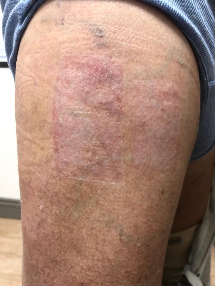
Clinical photograph of a 73-year-old male's right thigh demonstrating a well-healed split-thickness skin graft donor site. The donor site is a clearly demarcated, rectangular area characterized by a reddish-pink hue that contrasts with the surrounding tan-colored, sun-damaged skin. The texture of the graft site is slightly raised and smooth with a subtle reticular pattern, indicating a resolved state following previous bullous eruptions. The surrounding skin shows signs of chronological aging and actinic damage, including solar lentigines, fine rhytides, and scattered areas of hyperpigmentation and ecchymosis. This image illustrates the clinical appearance of a donor site following successful treatment of bullous pemphigoid (BP) lesions that had emerged as an isomorphic response (Koebner phenomenon) to surgical trauma. The visual focus is on the complete resolution of tense bullae and the preservation of the rectangular donor site borders without active inflammation or blistering.
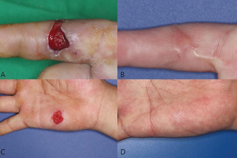
Clinical photograph series demonstrating the progression and outcomes of a conventional split-thickness skin graft (STSG) for a hand injury. The four-panel figure illustrates both the recipient and donor sites at different stages. Panel A shows a preoperative view of a full-thickness skin defect on the volar aspect of a finger, characterized by an open wound with visible deep red granulation tissue. Panel B displays the same recipient site at 6 months postoperatively, showing a well-healed graft with minimal scarring and good tissue integration. Panel C depicts the donor site on the hypothenar eminence of the palm at postoperative day 5, presenting as a raw, erythematous area following graft harvest. Panel D shows the donor site at 6 months postoperatively, demonstrating complete epithelialization with slight hyperpigmentation and texture changes consistent with a mature scar. This image set serves as an educational reference for plastic and reconstructive surgery, highlighting surgical wound healing, graft take, and long-term aesthetic outcomes in hand surgery.
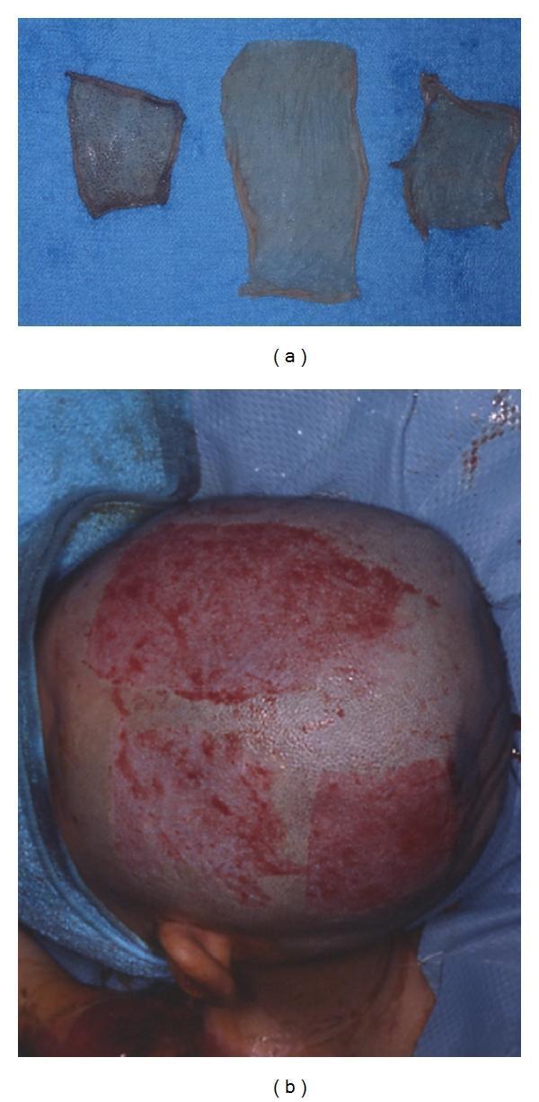
A two-part clinical photograph illustrating split-thickness skin graft (STSG) harvesting. Image (a) displays three harvested skin grafts of approximately 350 μm thickness resting on a blue surgical drape. The grafts exhibit a translucent, pale appearance with visible dermal patterning and irregular edges. Image (b) shows the donor site on a shaved human scalp immediately following the procedure. The harvested areas appear as raw, erythematous, rectangular patches with punctate bleeding, characteristic of a split-thickness donor site where the dermal papillae are exposed. The use of the hair-bearing scalp as a donor site is demonstrated, an approach utilized to facilitate rapid re-epithelialization via resident hair follicles and to conceal subsequent scarring. This visual material is intended for surgical education regarding dermatologic reconstruction, specifically focusing on graft harvesting techniques and donor site management in plastic and reconstructive surgery.
pedicle flap free flap reconstruction plastic surgery
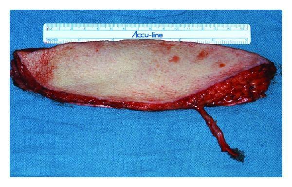
This clinical photograph displays a harvested anterolateral thigh (ALT) free flap, a versatile tool in reconstructive plastic surgery. The flap is shown ex vivo on a sterile blue surgical drape, accompanied by a measurement ruler for scale. The skin paddle is elongated and elliptical, featuring a pale, uniform cutaneous surface. The deep margin reveals harvested subcutaneous adipose tissue and fascia with characteristic reddish, irregular, and raw textures. A prominent feature is the long vascular pedicle, a slender tubular structure extending from the inferior aspect of the flap, which provides the necessary blood supply (artery and venae comitantes) for microsurgical anastomosis at the recipient site. This visual demonstrates the significant tissue volume and generous pedicle length typical of the ALT flap, making it ideal for large soft tissue defects, such as those resulting from head and neck cancer resections. Educational focus is on surgical flap anatomy, vascular pedicle identification, and tissue composition for microsurgical reconstruction.
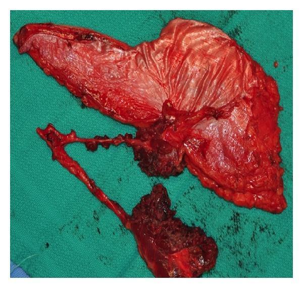
This clinical photograph shows a harvested anterolateral thigh (ALT) free flap, a versatile fasciocutaneous flap used in reconstructive surgery. The specimen is displayed against a green surgical drape immediately following harvest. The flap is composed of a large cutaneous portion and a complex vascular pedicle. Notably, the tissue has been divided into separate skin islands based on multiple perforators branching from the main descending branch of the lateral circumflex femoral artery. The vascular pedicle is visible as a long, branching structure with patent vessels and associated cuff of connective tissue. The deep surface of the flap shows the fascia and subcutaneous adipose tissue, which appears highly vascularized with a reddish-pink hue. This image illustrates the anatomical basis for creating chimera or multi-paddle flaps, allowing a single donor site to reconstruct non-contiguous defects, such as combined intraoral and extraoral maxillofacial defects. This is a key concept in advanced plastic and reconstructive surgery, highlighting the flap's adaptability in complex head and neck reconstruction.
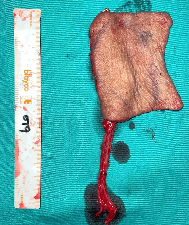
Clinical photograph of a harvested free radial forearm fasciocutaneous (RFFF) flap, commonly used in reconstructive plastic surgery for soft tissue coverage. The image displays a roughly rectangular skin paddle with pale pink to flesh-toned pigmentation and natural skin creases. The flap is oriented vertically on a green sterile surgical drape. Attached to the inferior aspect is a long vascular pedicle, which includes the radial artery and accompanying vena comitans, appearing as a tubular, bright red structure indicative of fresh harvest. A surgical ruler is positioned to the left of the flap to provide a scale for dimension assessment, confirming a size of approximately 9x6 cm. Visible surgical markings and minor bruising are present on the epidermal surface. This image serves as a high-fidelity representation of a microvascular free flap donor site preparation, illustrating the relationship between the cutaneous tissue island and its supplying blood vessels prior to anastomosis at the recipient site, such as for orbital or facial reconstruction.
replantation finger microsurgery postoperative hand rehabilitation
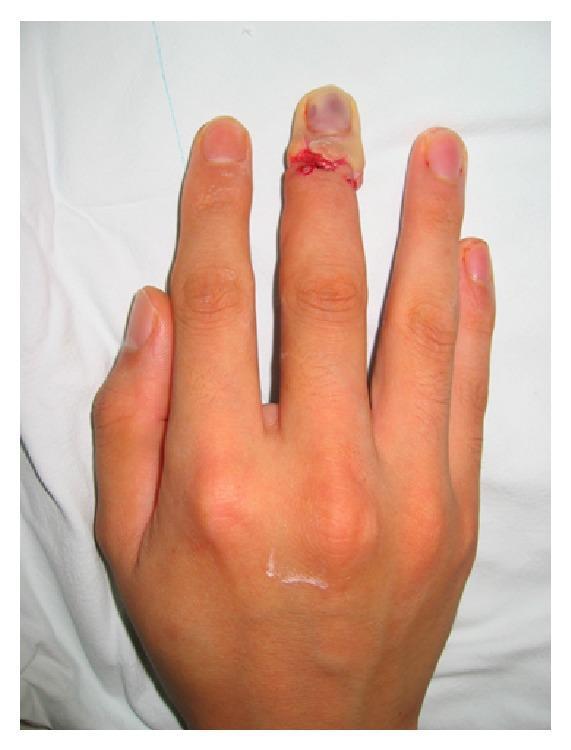
A clinical photograph of a patient's hand following distal digit replantation surgery. The image focuses on the middle finger, which has undergone a replantation procedure at the distal interphalangeal (DIP) joint or zone I level. A circumferential surgical incision is visible, secured with sutures, and showing signs of raw, disrupted tissue and minor blood staining at the site of anastomosis. The distal tip of the finger exhibits significant signs of vascular compromise, characterized by a dusky, cyanotic, and bluish discoloration visible beneath the nail plate and across the fingertip skin. This visual presentation is indicative of arterial insufficiency or venous congestion, suggesting impaired peripheral perfusion to the replanted segment. The surrounding digits and the dorsal aspect of the hand appear otherwise normal in color and morphology. This image serves as a clinical example of postoperative monitoring for vascular patency in microsurgery and digit salvage procedures.
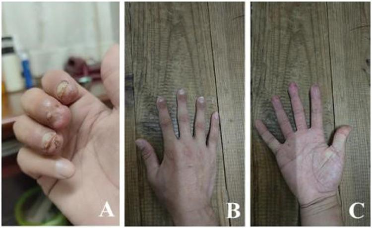
This set of clinical photographs illustrates the preoperative trauma and postoperative long-term results of a multiple fingertip replantation. Image A shows a preoperative view of the right hand featuring traumatic complete amputations of the index, middle, and ring fingertips at the level of the nail bed (Tamai Zone 1). Visible findings include irregular wound margins, severe tissue contusion, and contamination of the distal phalanx regions. Images B (dorsal view) and C (palmar view) demonstrate the patient’s right hand several months after emergency supermicrosurgery, including end-to-end anastomosis of the arcuate arteries and fracture fixation. The postoperative images reveal successful tissue survival with well-healed surgical sites, preserved finger length, and nearly normal cosmetic appearance. The skin texture and color on both the dorsal and palmar aspects of the replanted digits appear healthy and consistent with the surrounding anatomy, indicating successful revascularization and functional recovery of the digital pulp and nail units.
tissue expander breast reconstruction post mastectomy plastic surgery
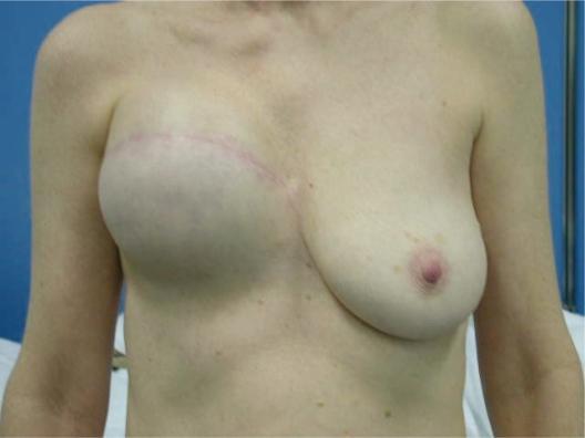
This clinical photograph shows a frontal view of a patient’s chest, illustrating post-mastectomy breast reconstruction with a tissue expander on the right side. The right breast mound appears significantly enlarged, firm, and rounded, lacking the natural ptosis seen in the contralateral left breast. A prominent, transverse surgical scar is visible across the upper quadrant of the right breast, extending medially towards the sternum. The right nipple-areolar complex is absent, likely as a result of a nipple-sparing or total mastectomy followed by primary expansion. In contrast, the left breast displays a natural teardrop shape with a normal nipple-areolar complex and typical skin pigmentation. This image serves as an educational example of the second stage of breast reconstruction (expansion phase), demonstrating the volumetric difference between a prosthetic expander and native breast tissue. It is relevant for plastic and reconstructive surgery training, specifically focusing on oncology-related breast restoration and the management of tissue expanders.
This composite of clinical photographs and 3D renderings illustrates a multi-stage approach to autologous breast reconstruction following mastectomy. Panel A shows a patient post-initial surgery with a tissue expander (TE) in the right breast and preoperative markings for a mastopexy on the contralateral left breast to address ptosis and symmetry. Panel B, captured 4-6 months later, displays the expanded right breast and a stabilized left mastopexy; it includes a 3D digital reconstruction and a physical 3D-printed breast mold created by mirroring the contralateral breast's shape. Markings on the lower abdomen indicate the donor site for a Deep Inferior Epigastric Perforator (DIEP) flap. Panel C documents the intraoperative phase where the 3D-printed mold is used to shape the DIEP flap tissue, followed by the final postoperative clinical result showing restored bilateral breast symmetry, volume, and contour. The workflow highlights the integration of 3D printing technology in precision plastic and reconstructive surgery to achieve optimal aesthetic outcomes in breast cancer patients.
Occupational Therapy in Plastic Surgery
Brief Review of Surgical Procedures, Pre-Operative and Post-Operative OT Management
1. OVERVIEW: OT AND PLASTIC SURGERY
- Biomechanical - restoring ROM, strength, endurance after reconstructive procedures
- Rehabilitative/Compensatory - adaptive techniques and equipment when full functional return is limited
- Person-Environment-Occupation (PEO) - optimizing fit between person, their tasks, and their environment
- Psychosocial (MOHO, CBT-informed) - addressing body image, identity, grief, and social re-engagement (Bruce & Borg; Creek & Lougher; Early)
2. REVIEW OF PLASTIC SURGICAL PROCEDURES
A. Grafts
1. Skin Grafts
| Feature | Split-Thickness Skin Graft (STSG) | Full-Thickness Skin Graft (FTSG) |
|---|---|---|
| Layers | Epidermis + partial dermis | Epidermis + all dermis |
| Harvest tool | Dermatome (electric/air-powered) | Scalpel |
| Common donor sites | Thigh, buttock, scalp | Pre-/post-auricular, groin, inner arm, supraclavicular |
| Donor site healing | Heals by re-epithelialization (10-14 days); can be re-harvested | Must be closed primarily; limited size |
| Graft contraction | More secondary contraction | Less contraction; better cosmetic result |
| Take rate | Higher (thinner → easier revascularization) | Slightly lower (dermis thickness limits imbibition) |
| Best used for | Large wounds, burns, raw areas after tumor excision | Face, hands, joint surfaces, areas requiring cosmesis |
| Appearance | Shiny, depressed, colour mismatch common | Better colour match, especially when harvested locally |
- Plasmatic imbibition (0-48 hrs): Serum from wound bed diffuses into graft - nourishes it before vessels form
- Inosculation (48-72 hrs): Blood vessels from wound bed grow to meet vessels in graft ("kissing" - from Latin inosculate)
- Revascularization (day 3-7): Full vascular ingrowth; graft turns pink
2. Nerve Grafts
- Used to bridge nerve defects when primary repair under tension is not possible
- Sural nerve (from calf): most common donor; purely sensory; provides 30-40 cm of cable grafts
- Medial antebrachial cutaneous nerve: upper limb donor
- Graft acts as a scaffold - donor Schwann cells guide regenerating axons
- Nerve regeneration: ~1 mm/day (1 inch/month) - recovery may take months to years depending on gap length
- Nerve conduits (collagen, silicone): alternative for small gaps (<3 cm)
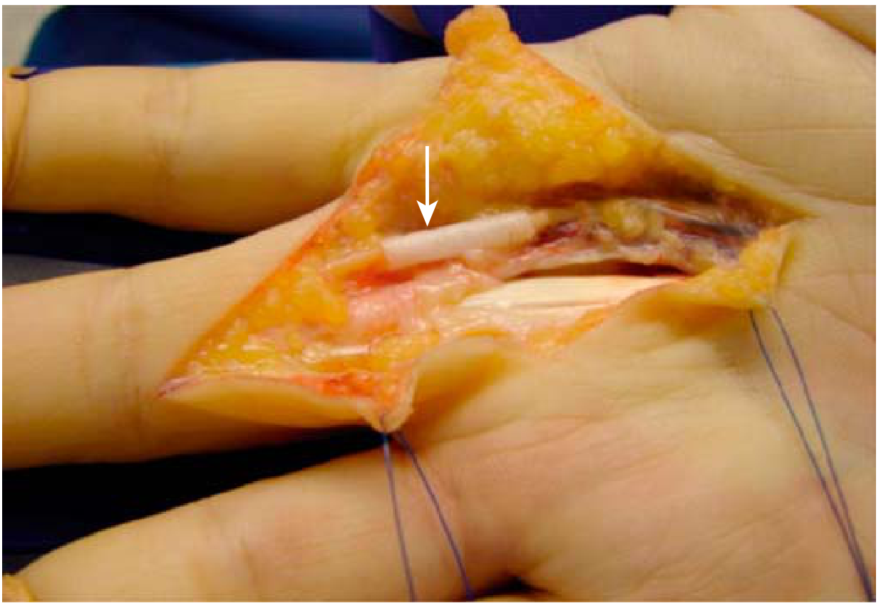
3. Bone Grafts
- Autograft: cancellous (iliac crest) or cortical (fibula, rib); gold standard
- Allograft: cadaveric bone; used when autograft volume insufficient
- Vascularized bone graft: e.g., free fibula flap - carries own blood supply; used for large mandible or long bone reconstruction
- OT role: protective splinting/orthosis post-op; progressive loading as graft incorporates
4. Tendon Grafts
- Palmaris longus (forearm; absent in ~15% of population): most used for tendon reconstruction
- Plantaris (from leg): long graft for bridging large defects
- Toe extensors: for hand tendon reconstruction
- Used for primary tendon reconstruction when primary repair impossible (segmental loss)
B. Flaps
1. Local/Random Pattern Flaps (Mulholland and Greenfield's Surgery)
- Perfused by dermal plexus from adjacent tissue
- Movements: rotation, advancement, transposition
- Examples: Z-plasty (lengthens contracted scars), W-plasty, rhomboid/Limberg flap, bilobed flap
- Color and texture match is excellent (adjacent tissue)
- Tissue expansion: expander placed subcutaneously, gradually inflated over weeks to create new skin; used for scalp, breast, burn reconstruction
2. Axial / Pedicle Flaps (Mulholland and Greenfield's Surgery)
- Fasciocutaneous flaps: Skin + fascia + named vessels. Example: Radial forearm flap (thin, pliable; used for head/neck/hand reconstruction)
- Musculocutaneous (myocutaneous) flaps: Muscle + overlying skin. Examples:
- Pectoralis major flap: head and neck defects
- Latissimus dorsi flap: chest wall, breast reconstruction, back
- Rectus abdominis (TRAM) flap: breast, perineum, abdomen
- Gastrocnemius flap: knee coverage
- Perforator flaps: defined by perforating vessels; less donor morbidity. Example: DIEP flap (deep inferior epigastric perforator) for breast reconstruction - preserves rectus muscle
3. Free Flaps (Free Tissue Transfer / Microsurgery)
- Flap is completely detached and vessels microsurgically anastomosed to recipient vessels
- Requires operating microscope, fine sutures (9-0 to 11-0 nylon), microvascular expertise
- Examples:
- Anterolateral thigh (ALT) flap: versatile, large volume; head/neck/extremity
- Free radial forearm flap: thin, pliable; oral cavity, pharynx reconstruction
- Free fibula flap: vascularized bone for mandible, long bone
- DIEP flap: breast reconstruction preserving rectus muscle
- Gracilis flap: functional muscle transfer for facial reanimation, extremity
C. Tissue Transplants
1. Replantation
- Reattachment of completely amputated parts (digit, hand, arm)
- Indications for replantation: thumb amputation, multiple digit amputations, any part in child, wrist/forearm/upper arm level amputations, ring avulsion, single digit distal to FDS insertion
- Contraindications: severely crushed/mangled parts, avulsion injuries with extensive vessel damage, multiple comorbidities, prolonged ischemia, single finger in elderly
- Order of repair (simplified): bone fixation → extensor tendon → flexor tendon → artery → nerve → vein → skin
- Post-operative vascular monitoring is critical (hourly checks for color, temperature, capillary refill, turgor)
2. Composite Tissue Allotransplantation (CTA) / Vascularized Composite Allotransplantation (VCA)
- Transplantation of composite tissue from a donor (including skin, muscle, bone, nerve, vessels)
- Examples: hand transplantation, face transplantation
- Requires lifelong immunosuppression
- OT plays a central role in functional re-education post-transplant (motor re-learning, sensory re-education)
3. Alloderm / Biological Scaffolds
- Acellular dermal matrix (ADM) used for breast reconstruction, tendon coverage, hernia repair
- Acts as scaffold for tissue ingrowth
D. Cosmetic / Aesthetic Surgery Procedures
| Category | Procedure | Description |
|---|---|---|
| Face | Rhinoplasty | Reshaping nasal structure |
| Rhytidectomy (facelift) | Excises skin, tightens SMAS; reduces facial ageing | |
| Blepharoplasty | Upper/lower eyelid skin and fat excision | |
| Brow lift (forehead lift) | Elevates ptotic brow; reduces forehead lines | |
| Otoplasty | Ear reshaping (prominent ears) | |
| Mentoplasty | Chin augmentation/reduction | |
| Breast | Augmentation mammoplasty | Implants (saline/silicone); incisions: inframammary, periareolar, transaxillary |
| Mastopexy (breast lift) | Repositions ptotic breast; may combine with augmentation | |
| Reduction mammoplasty | Removes glandular tissue, fat, skin; relieves musculoskeletal symptoms | |
| Gynecomastia correction | Male breast tissue reduction | |
| Body | Liposuction/Liposculpture | Suction-assisted fat removal |
| Abdominoplasty (tummy tuck) | Excises excess abdominal skin and fat; repairs rectus diastasis | |
| Body contouring post-weight loss | Large skin panel excisions (pannus, arm, thigh lifts) |
E. Reconstructive Plastic Surgery Procedures of Special OT Relevance
| Procedure | Indication | OT Involvement |
|---|---|---|
| Post-mastectomy breast reconstruction | Breast cancer; improves body image and quality of life | Shoulder ROM, lymphoedema management, ADL post-op |
| Hand reconstruction | Trauma, burns, congenital | Splinting, sensorimotor re-education, ADL retraining |
| Craniofacial surgery | Cleft lip/palate, craniosynostosis, facial trauma | Feeding, oral motor, developmental support (pediatric OT) |
| Pressure injury/ulcer reconstruction | Flap coverage of stage IV ulcers | Pressure relief seating, positioning, skin inspection |
| Lower extremity reconstruction | Limb salvage after trauma/tumour | Progressive weight-bearing, adaptive ambulation aids |
| Facial reanimation | Facial palsy (Bell's, trauma, tumour) | Facial muscle re-education, eye protection, eating aids |
3. PRE-OPERATIVE OT MANAGEMENT
A. Goals
- Establish functional baseline for outcome comparison
- Educate patient on procedure, expected restrictions, recovery timeline
- Prepare home and equipment
- Address psychological concerns regarding surgery, appearance, and function
- Optimize pre-operative function (prehabilitation)
B. Assessment
- ROM, strength (grip/pinch dynamometry where relevant), sensation, coordination, dexterity
- ADL and IADL performance baseline
- DASH / QuickDASH for upper limb procedures
- COPM - identify patient's occupational priorities
- Barthel Index / FIM for major reconstructive cases (head/neck cancer, breast cancer)
- Body image and self-concept screening
- Anxiety and depression (PHQ-9, GAD-7)
- Expectations from surgery: are they realistic?
- Body Dysmorphic Disorder (BDD) screening: OT should be alert to patients with cosmetic concerns; BDD (preoccupation with imagined or slight defect) is a contraindication to cosmetic surgery; refer to psychology
- Social support network
- Occupational identity: how does the condition/planned surgery relate to the patient's work, roles, and self-image?
- Will post-operative restrictions affect home access or routine?
- Any pre-existing hazards (fall risks, trip hazards)?
- Caregiver availability
C. Pre-Operative Education
- Explain post-operative restrictions relevant to OT function:
- Graft surgery: strict immobilization of graft site for 5-7 days; no shear force
- Free flap surgery: positioning requirements; avoid compression of pedicle; no tight clothing
- Replantation: strict elevation; no smoking (vasospasm); temperature protection; no pressure on replanted digit
- Breast reconstruction: shoulder mobility restrictions; drain management; no lifting
- Abdominoplasty/body contouring: abdominal binder; limited trunk flexion initially; activity restrictions
- Adaptive equipment identified and trialed before surgery where possible (reachers, dressing aids, shower chair)
- Splints fabricated pre-operatively where indicated (e.g., resting hand splints before burn reconstruction)
- Compression garment measured and ordered in advance (breast surgery, lymphoedema)
- Upper limb strengthening before shoulder/breast surgery
- Practice of one-handed techniques before procedures limiting dominant hand
- Breathing exercises before chest/breast procedures
- Gentle aerobic conditioning to improve surgical recovery
- Explore and validate concerns about outcome
- Discuss realistic expectations: grafts vs. original skin appearance; functional vs. cosmetic outcomes
- For oncology-related reconstruction: address grief about lost body part (mastectomy, amputation) alongside expectations of the reconstructive procedure
- Reference: Bruce & Borg (psychosocial frames of reference); Early (mental health concepts)
4. POST-OPERATIVE OT MANAGEMENT
A. Immediate Post-Operative Phase (Days 1-7)
- Graft sites: strict immobilization for 5-7 days while revascularization occurs (plasmatic imbibition and inosculation); patient education about not touching, not applying pressure, or moving graft
- Flap sites: gentle positioning to avoid compression of pedicle; no tight dressings over pedicle
- Replanted parts: strict elevation (above heart level); hourly vascular checks (color, temperature, capillary refill); no smoking; warm environment; avoid vasoconstrictors (caffeine, cold)
- Free flap vascular monitoring: essential - signs of arterial compromise (pale, cool, no capillary refill) vs. venous congestion (dusky, congested, rapid capillary refill)

- Elevate operated extremity above heart level (reduces oedema, protects flap)
- Specific positional requirements vary by body region and flap type
- Protect donor sites from pressure
- Positioning strategies for comfort
- Relaxation and distraction techniques
- Therapeutic occupation: gentle meaningful activity as pain distraction once cleared
- Provide assistance/adaptive equipment for washing, dressing, feeding within restrictions
- One-handed techniques when operated limb is immobilized
- Pre-positioned adaptive equipment used now
B. Mobilization Phase (Week 1-3)
- Gradual active ROM initiated at grafted/reconstructed joints
- Begin distally, progress proximally
- Tendon gliding exercises if tendons exposed or reconstructed
- Surgeon-guided protocol for replanted digits (typically modified Kleinert/Duran approach)
- Progressive compression once graft is mature enough
- Retrograde massage
- Active ROM as muscle pump
- Lymphoedema management techniques for breast/axillary surgery patients (referral to lymphoedema specialist if needed)
- Scar massage: circular friction over healed graft/flap edges and donor sites
- Silicone gel sheeting over grafted areas
- Custom pressure garments for large graft areas, burn reconstruction, or post-mastectomy
- Serial static or dynamic splinting for contracture prevention if graft lies over a joint
- Grafted skin has altered sensation - initially protective sensation only
- Desensitization for hypersensitive graft margins
- Sensory re-education for nerve grafts and replanted digits (see Nerve Injuries section)
- Texture grading: soft → rough; localization training; stereognosis training
- Graduated return to bilateral activities
- Work within graft/flap protection protocols
- Adaptive equipment weaned as function returns
C. Rehabilitation Phase (Weeks 3-12)
- Light resistance: putty, theraband, hand exercisers
- Progress to heavier resistance as tissue healing progresses
- Functional strengthening through graded activity and craft
- Shoulder ROM restoration: pendulum exercises → active ROM → strengthening
- Watch for: restricted shoulder elevation (common post-latissimus dorsi flap), axillary web syndrome ("cording")
- Bra/prosthesis fitting advice and training
- Drain management education (if discharged with drains)
- Return to domestic and work tasks
- Progressive fine motor and coordination retraining
- Dexterity exercises (9-hole peg test as goal-setting tool)
- Return to handwriting, keyboard use, tool use
- Work simulation specific to patient's job
- Oral motor retraining after oral cavity reconstruction (eating, swallowing)
- Communication aids if speech affected
- Cervical ROM exercises if neck flaps restrict rotation
- Facial scar management: pressure masks, silicone, massage
- Graduated weight-bearing as flap and bone heal
- Adaptive ambulation aids progression
- Skin inspection training for insensate grafted areas
| Procedure | Splint Type | Purpose |
|---|---|---|
| Skin graft over finger/hand | Protective splint → scar management splint | Immobilize graft → prevent scar contracture |
| Nerve graft | Protective splint initially; then functional | Protect repair; maintain joint position during re-innervation |
| Tendon graft | Zone-specific protocol (see Tendon section) | Prevent adhesion; protect repair |
| Replantation | Protective dorsal blocking splint; then mobilization splint | Protect repair; prevent adhesion |
| Post-flap (joint coverage) | Serial static or dynamic splint | Prevent contracture across reconstructed joint |
| Web space reconstruction | Web space splint/C-bar | Maintain web space opening |
D. Psychosocial Rehabilitation (Bruce & Borg; Creek & Lougher; Early)
- Oncological reconstruction (mastectomy, amputation, head/neck cancer): grief response for loss of body part; adjustment to new appearance; identity reconstruction
- OT facilitates re-engagement with meaningful occupations as a vehicle for identity rebuilding
- Model of Human Occupation (MOHO): addresses volition (motivation), habituation (roles and routines), and performance capacity
- Graded exposure to social situations post-surgery (particularly for facial/visible reconstructions)
- Social Skills Training: practiced in OT sessions for patients with social anxiety related to appearance
- Peer support groups for breast cancer survivors, burn survivors, people with facial differences
- School re-entry programme for pediatric patients (Case-Smith): liaison with teachers, peer education
- Training in application of paramedical cosmetics (e.g., Dermablend, Covermark) over scars, graft colour differences, dyspigmentation
- Available through specialist nurses and OT in many burn/reconstructive centres
- Job demands analysis: what physical and appearance-related demands does the patient's work involve?
- Graded return to work: modified duties → full duties
- Self-employment and business planning if permanent functional change has occurred
- Leisure activity reintegration: sports, crafts, social activities
- Body image in intimate relationships
- Education about physical limitations and activity timing post-operatively
- Referral to psychosexual counselling where needed
E. Paediatric Plastic Surgery (Case-Smith; Kramer & Hinojosa)
- Cleft lip and palate: OT for oral motor function, feeding, speech support; later: facial scar management, dental OT
- Syndactyly (web fingers): post-surgical web space splinting, scar management, progressive ROM, hand function retraining
- Polydactyly: post-excision ROM, strengthening, functional hand re-education
- Congenital hand differences (radial club hand, absent radius, symbrachydactyly): prosthetic fitting, adaptive techniques, developmental task support
- Craniosynostosis: post-cranial vault remodeling; cognitive, sensory, and developmental assessment; school support
- Play-based therapy as the therapeutic medium
- Developmental milestones guide what is expected of the repaired structure
- Family is the primary rehabilitation partner - parent education is central
- Splints must be regularly modified for growth
- Psychosocial impact on child and family (sibling, peer relationships)
5. SUMMARY TABLE: OT ACROSS PLASTIC SURGICAL CATEGORIES
| Procedure | Pre-Op OT Focus | Post-Op (Acute) OT Focus | Post-Op (Rehab) OT Focus |
|---|---|---|---|
| Skin graft | Baseline assessment; education; equipment; donor site preparation | Graft protection; elevation; positioning; ADL one-handed | Scar management; ROM; progressive ADL; sensory re-ed |
| Pedicle/free flap | Function baseline; education re: restrictions; psychosocial prep | Flap monitoring; positioning; avoid compression; basic ADL | ROM; scar management; ADL; work return |
| Replantation | Pre-op ADL baseline; one-handed training | Elevation; vascular monitoring; protection | Tendon/nerve protocol; sensory re-ed; fine motor; work return |
| Breast reconstruction | Shoulder baseline; prehabilitation; psychological prep | Drain management; shoulder protection; positioning | Shoulder ROM; lymphoedema; body image; work return |
| Cosmetic surgery | Psychological screening (BDD); realistic expectations; ADL prep | Activity restrictions; wound/scar care; positioning | Scar management; gradual ADL; psychosocial support |
| Paediatric hand | Family education; developmental baseline | Protective splint; parental involvement; play | Growth-adjusted splints; developmental activities; school support |
| Head/neck oncological | Functional baseline; nutritional planning | Positioning; ADL; oral motor; communication | Facial scar management; oral motor; social re-entry; work return |
- Pedretti's Occupational Therapy: Practice Skills for Physical Dysfunction, Pendleton & Schultz-Krohn
- Occupational Therapy for Physical Dysfunction, Radomski & Trombly
- Occupational Therapy and Physical Dysfunction, Turner, Foster & Johnson
- Willard & Spackman's Occupational Therapy
- Mulholland and Greenfield's Surgery - Chapter 107 (Skin Grafts, Flaps, Tissue Expansion)
- Occupational Therapy and Mental Health, Creek & Lougher
- Mental Health Concepts for the OTA, Early
- Frames of Reference in Psychosocial OT, Bruce & Borg
- OT for Children, Case-Smith; Frames of Reference for Pediatric OT, Kramer & Hinojosa
E. Oncological rehabilitation with emphasis on post operative Management. F. Brachial plexus injury G. Erb's Palsy H. Klumpke's Paralys Recommended book(s) for Reference: 1. Pedretti’s Practice skills for physical dysfunction edited by Heidi McHugh Pendleton ,Winifred Schultz Krohn 2. Occupational Therapy for Physical Dysfunction by Mary Vining Radomski, Catherine A Trombly 3. Occupational Therapy and Physical Dysfunction, Principles, Skills and Practice by Ann Turner, Margaret Foster, Sybil E Johnson 4. Introduction to Occupational Therapy by Hussey Subonis ,Chafea O Brien 5. Occupational Therapy and Mental Health edited by Jennifer Creek, Lesley Lougher 6. Mental Health Concepts and Techniques for the Occupational Therapy Assistant by Mary Beth Early 7. Frames of Reference in Psychosocial Occupational Therapy by Mary Ann Bruce, Barbara Borg 8. Willard & Spackman’s Occupational Therapy 9. Occupational Therapy for children by Jane Case Smith 10. Frames of Reference for Pediatric Occupational Therapy by Paula Kramer , Jim Hinojosa
brachial plexus anatomy diagram roots trunks cords
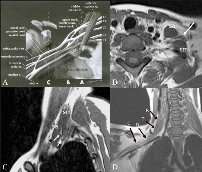
This composite educational graphic illustrates the normal anatomy of the brachial plexus through anatomical diagrams and Magnetic Resonance Imaging (MRI). Panel A is an anatomical diagram depicting the plexus architecture from roots (C5-T1) to terminal branches, labeled with musculoskeletal landmarks like the scalene muscles and coracoid process. Panel B (axial) and Panel C (sagittal) are T1-weighted MRI scans demonstrating the interscalene triangle, defined by the anterior scalene (sa) and middle scalene (sm) muscles. These muscles serve as primary radiological landmarks for identifying the neural roots and trunks (indicated by arrows). Panel D provides an oblique coronal T1-weighted MRI view, tracing the sequential segments of the right brachial plexus: roots (R), trunks (T), divisions (D), and cords (C). This resource is designed for medical education in radiology and neurology to assist in the localization of neural structures and the diagnostic evaluation of conditions like brachial plexopathy, neurogenic tumors, or Pancoast tumors.
This composite educational resource comprises three Magnetic Resonance Neurography (MRN) coronal views (a, b, c) and a correlating schematic anatomical diagram (d) illustrating a severe traumatic brachial plexus injury. The right side of the images displays normal brachial plexus anatomy, with continuous nerve structures including the upper trunk (1), middle trunk (2), C8 root (3), and Th1 root (4). In contrast, the left side demonstrates a total rupture of the brachial plexus (dashed arrows). This injury is characterized by the complete discontinuity of the neural trunks and cords, accompanied by a large axillary cavity hematoma (curved dashed arrows). The schematic (d) highlights the side-to-side difference, showing the organized right-sided roots (C5-Th1) and trunks versus the disorganized, hemorrhagic area on the left. This material is designed for advanced medical education in radiology and neurosurgery, focusing on diagnostic imaging features of high-grade nerve trauma, specifically Seddon grade 3-5 injuries (neurotmesis) and the identification of postganglionic plexopathy.
Erb palsy waiter tip position infant neonatal brachial plexus
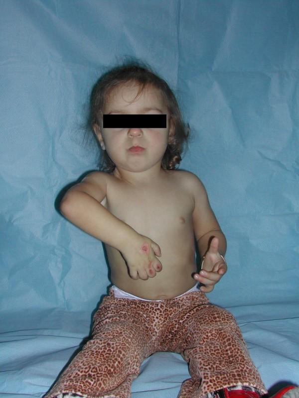
This clinical photograph shows a pediatric patient presenting with characteristic physical signs of obstetric brachial plexus palsy (specifically Waiter's Tip deformity). The left upper limb demonstrates significant pathological positioning: the shoulder is adducted and internally rotated, the elbow is extended, and the wrist and fingers are fixed in a flexed position. There are visible red, erosive skin lesions or abrasions on the dorsal aspect of the left hand, particularly over the knuckles, which can occur due to lack of sensation or inability to protect the limb (sensory deficit-related injury). The right upper limb appears relatively unaffected, positioned with slight elbow flexion and extended fingers. This image illustrates the long-term musculoskeletal consequences and secondary dermatological complications of total brachial plexus paralysis following unsuccessful neurotisation. It is an educational example of neonatal brachial plexus injury (NBPI) in a young child, highlighting limitations in shoulder abduction and external rotation.
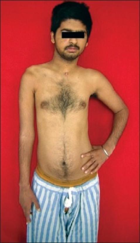
Clinical photograph of a young male patient demonstrating the characteristic physical presentation of a right-sided upper brachial plexus palsy (C5, C6, C7), likely following microneuroreconstruction. The image shows significant upper limb asymmetry: the right shoulder is depressed (slumped) compared to the left. The right arm exhibits postural abnormalities including internal rotation at the shoulder, adduction, and extension at the elbow, often referred to as a 'waiter's tip' position or Erb's palsy-like presentation. Muscle atrophy is visible in the right deltoid and pectoral regions. A small, well-healed, linear surgical scar (approximately 2 cm) is located in the midline suprasternal/cervical region, consistent with prior nerve reconstruction surgery or access to the brachial plexus. In contrast, the left upper limb shows normal muscle bulk and posture, with the hand resting on the hip. This visual aid is primarily used for teaching clinical signs of peripheral nerve injury and the outcomes of surgical nerve repair in neurology and orthopedics.
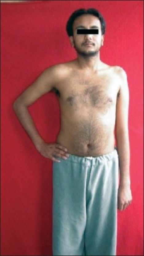
A clinical photograph of a male patient demonstrating the physical presentation of a left-sided upper brachial plexus palsy (Erb-Duchenne palsy), involving the C5 and C6 nerve roots. The image shows significant postural asymmetry between the upper limbs. The affected left arm exhibits classic clinical signs, including adduction at the shoulder and internal rotation of the humerus. There is visible muscle atrophy and a loss of rounded contour in the left deltoid and shoulder girdle compared to the healthy right side. Additionally, the left shoulder is positioned lower than the right. The patient's right arm displays a normal neutral position and muscle bulk. This visual serves as a primary clinical example of peripheral nerve injury manifestations, specifically highlighting the 'waiter's tip' position resulting from paralysis of the abductors and external rotators of the shoulder.
Klumpke paralysis claw hand intrinsic Horner syndrome
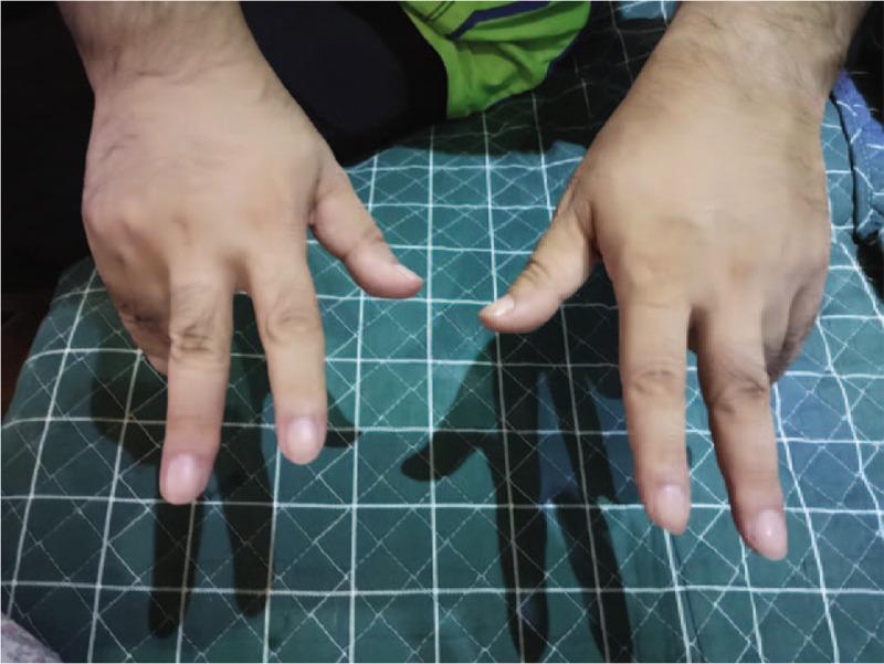
This clinical photograph shows the bilateral hands of a patient exhibiting a characteristic 'claw hand' (main en griffe) deformity. The dorsal view reveals a symmetric presentation in which the metacarpophalangeal (MCP) joints are hyperextended, while the proximal interphalangeal (PIP) and distal interphalangeal (DIP) joints are flexed. This specific posture is indicative of intrinsic muscle paralysis, typically involving the ulnar lumbrical and interosseous muscles. The visual manifestation corresponds with clinical findings of motor weakness in finger extensors and ulnar-innervated intrinsic hand muscles. The image serves as an educational example of peripheral nerve dysfunction or regional variants of neurological conditions like Guillain-Barr syndrome (GBS), demonstrating the imbalance between extrinsic long extensors/flexors and the paralyzed intrinsic muscles of the hand.
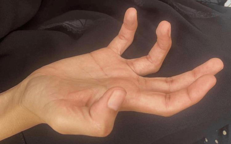
Clinical photograph of a right hand demonstrating a classic 'claw hand' deformity (main en griffe). The image illustrates characteristic hyperextension at the metacarpophalangeal (MCP) joints and flexion at the proximal and distal interphalangeal (IP) joints, most prominent in the middle, ring, and little fingers. Significant muscle wasting is visible, particularly involving the intrinsic hand muscles, thenar, and hypothenar eminences, resulting in a hollowed and flattened palmar appearance. The thumb is positioned in adduction. These findings are clinically diagnostic of severe distal polyneuropathy or intrinsic muscle paralysis, often associated with ulnar or median nerve involvement. In the specific clinical context provided, this manifestation serves as a landmark neurological sign for POEMS syndrome, representing chronic, severe motor nerve damage and secondary muscular atrophy. The skin appears intact but shows subtle wrinkling consistent with the underlying loss of muscle bulk and soft tissue volume.
cancer rehabilitation lymphedema arm breast cancer post mastectomy
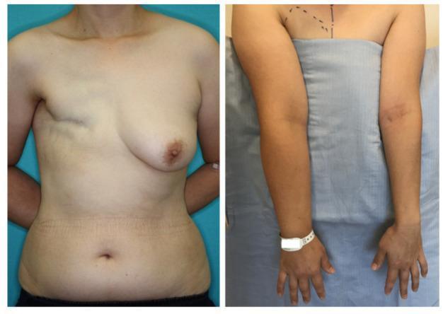
Two-panel clinical photograph of a 46-year-old female patient demonstrating post-surgical sequelae of breast cancer treatment. The left panel shows an anterior view of the torso highlighting significant thoracic asymmetry; the right breast is absent with a visible transverse mastectomy scar, while the left breast remains intact. The right axillary region shows hollow contours consistent with axillary lymph node dissection (ALND). The right panel provides a comparative view of the upper extremities, illustrating secondary lymphedema. The right arm exhibits marked circumferential swelling (non-pitting edema) in the upper arm, forearm, and hand compared to the contralateral side. The skin on the right arm appears taut with loss of normal anatomical landmarks around the elbow and wrist, consistent with ISL Stage 2B lymphedema. Surgical markings on the upper chest and abdomen indicate preoperative planning for breast reconstruction using a DIEP flap and lymphatic SCIP flap. This visual material serves as an educational reference for breast cancer-related lymphedema (BCRL) and post-mastectomy anatomical changes.
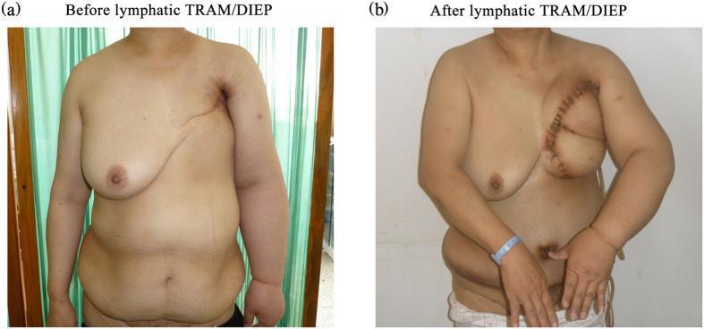
Clinical photograph comparing preoperative (a) and 2-week postoperative (b) status of a patient following a combined lymphatic TRAM/DIEP flap procedure for breast reconstruction and lymphedema treatment. Image (a) depicts the patient post-mastectomy with severe lymphedema of the left upper extremity, characterized by significant circumferential enlargement of the upper arm, forearm, and hand, alongside a flattened left chest wall with a healed transverse mastectomy scar. Image (b) shows the early postoperative result, demonstrating a reconstructed left breast using a vascularized tissue flap. A curved surgical incision with visible sutures or skin staples is present along the superior and medial borders of the newly constructed breast mound. Notably, there is a visible reduction in the volume and swelling of the left upper limb and hand compared to the preoperative state, illustrating the immediate effect of the lymph node transfer component of the surgery. This visual serves as a clinical case study for simultaneous breast reconstruction and surgical management of breast cancer-related lymphedema (BCRL).
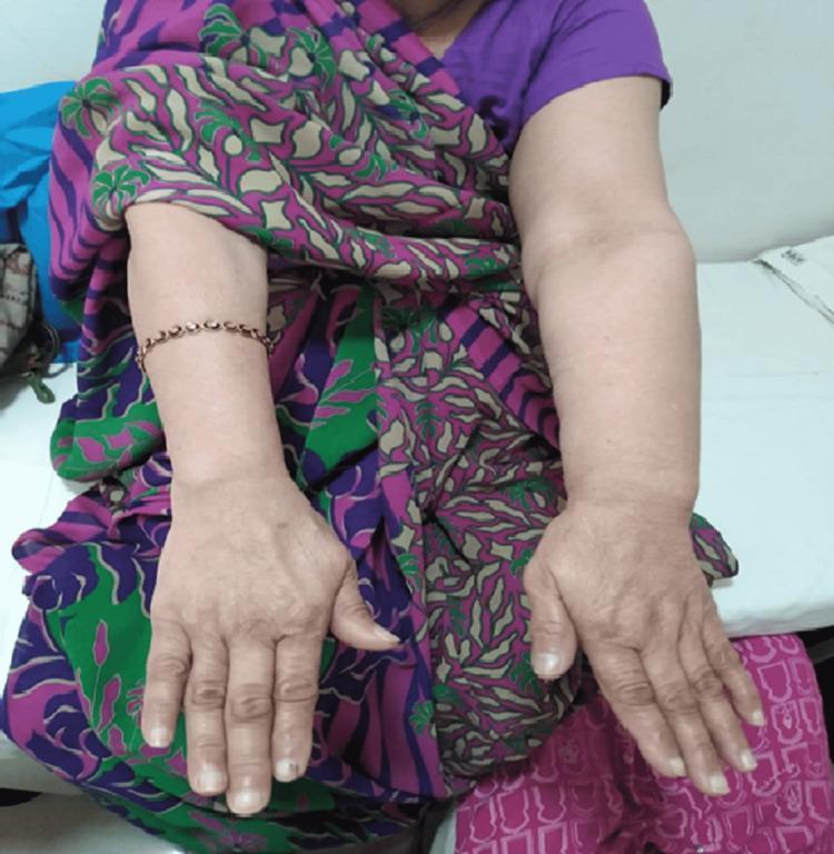
Clinical photograph of a patient's upper limbs positioned for comparison, demonstrating breast cancer-related lymphedema. The primary finding is significant unilateral swelling (edema) of the left upper limb compared to the unaffected right side. The left arm exhibits a marked increase in circumferential size, loss of normal anatomical contour, and a cylindrical appearance extending from the upper arm through the forearm and wrist. The skin on the affected side appears taut due to fluid accumulation. The unaffected right arm shows normal bony landmarks and muscle definition, with a bracelet loosely fitted at the wrist, highlighting the baseline limb size. The image is a classic representation of secondary lymphedema, a common sequela following radical mastectomy and axillary lymph node dissection. Educational focus includes the visual recognition of Stage II lymphedema and the importance of clinical observation in oncological rehabilitation.
E. Oncological Rehabilitation with Emphasis on Post-Operative Management
1. OVERVIEW: OT IN ONCOLOGICAL REHABILITATION
- Preventive (before treatment begins): baseline assessment, prehabilitation
- Restorative (after curative treatment): restoring function, returning to roles
- Supportive (during ongoing treatment): managing symptoms, maintaining ADL
- Palliative (advanced/terminal disease): maintaining quality of life, conserving energy, preserving meaningful occupation
2. COMMON CANCER TYPES AND SURGICAL PROCEDURES REQUIRING OT
| Cancer Type | Surgery | Primary OT Concerns |
|---|---|---|
| Breast cancer | Mastectomy (total/modified radical), lumpectomy, axillary lymph node dissection (ALND), sentinel node biopsy | Shoulder ROM, lymphoedema, body image, prosthesis |
| Head and neck cancer | Laryngectomy, glossectomy, mandibulectomy, neck dissection, parotidectomy | Communication, swallowing, facial function, neck ROM |
| Upper limb sarcoma | Wide local excision, limb salvage, or amputation | Upper limb function, prosthesis fitting, ADL |
| Lower limb sarcoma | Limb salvage, amputation | Mobility, ADL, prosthesis |
| Colorectal/abdominal | Colostomy, ileostomy, pelvic exenteration | Stoma management, continence, sexual function |
| Brain tumours | Craniotomy, resection | Cognitive deficits, hemiplegia, aphasia, ADL |
| Lung cancer | Lobectomy, pneumonectomy | Activity tolerance, energy conservation |
| Spine tumours | Spinal decompression/fusion | Mobilization, positioning, SCI-level-specific OT |
| Gynaecological | Hysterectomy, oophorectomy, pelvic node dissection | Lymphoedema, sexual function, ADL |
3. PRE-OPERATIVE OT MANAGEMENT (PREHABILITATION)
A. Assessment
- Functional baseline: ADL, hand strength, ROM, activity tolerance (6MWT)
- COPM - patient identifies occupational priorities
- Fatigue screening: FACT-Fatigue, Brief Fatigue Inventory
- Cognitive screening: if brain or CNS involvement anticipated
- Psychosocial assessment: anxiety, depression, social support, body image concerns
- Environmental assessment: home setup, workplace demands
B. Prehabilitation Interventions
- Strengthening exercises: especially shoulder for breast surgery patients; upper limb for sarcoma
- ADL practice: one-handed or adapted techniques pre-amputation
- Equipment ordering: reachers, dressing aids, shower chair
- Home modification planning: grab bars, ramp if needed
- Education: surgical procedure, expected restrictions, recovery timeline
- Psychological preparation: address cancer diagnosis-related anxiety; goal-setting
4. POST-OPERATIVE OT MANAGEMENT
A. Acute Post-Operative Phase
- Wound status, drain output, incision position
- Post-surgical activity restrictions (surgeon-specified)
- DVT risk (early mobilization is protective)
- Upper limb elevation post-axillary/limb surgery - reduces oedema
- Anti-deformity positioning post-head/neck surgery
- Functional seating and positioning for patients with new neurological deficits post-craniotomy
- Self-care within surgical restrictions
- Adaptive equipment provision
- One-handed techniques where relevant
B. Key Post-Operative OT Problems and Management
1. Lymphoedema
- Stage 0: latent (no visible oedema)
- Stage I: soft, pitting, reversible
- Stage II: non-pitting, fibrotic, not fully reversible
- Stage III: elephantiasis - gross deformity, skin changes
- Phase I (Intensive/Reduction): daily sessions for 2-4 weeks
- Manual Lymphatic Drainage (MLD): gentle skin-stretch massage in specific directional sequences to reroute lymph to functioning nodal basins
- Multi-layer bandaging: low-stretch compression bandaging to maintain reduction between sessions
- Remedial exercises: active exercises while bandaged - muscle pump effect
- Skin care: moisturization, hygiene, infection prevention (cellulitis is a major risk)
- Phase II (Maintenance/Self-management):
- Compression garments: custom-fitted sleeves/gloves worn daily for life
- Self-MLD: patient-performed maintenance drainage
- Exercise: regular aerobic and strengthening - no longer contraindicated; evidence supports safe exercise
- Skin hygiene: vigilant daily inspection, moisturization, avoid cuts/burns/injections in affected limb
- Avoid blood pressure cuffs, venepuncture, injections in affected limb
- Avoid constricting clothing, bags, watches on affected arm
- Protect from cuts and burns (infection triggers acute lymphoedema)
- Maintain healthy weight (obesity is a risk factor)
- Avoid extremes of temperature (saunas, hot tubs)
2. Cancer-Related Fatigue (CRF)
- Activity pacing: match activity to energy reserves; alternate high and low demand tasks; planned rest periods
- Energy conservation (the 4 Ps - Pace, Plan, Prioritize, Position)
- Fatigue diary: identify peak energy times; schedule demanding tasks then
- Graded activity: gradually increasing activity tolerance without provoking post-exertional malaise
- Sleep hygiene education: fatigue-sleep disruption cycle; structured rest without excessive daytime sleeping
- Meaningful activity: engagement in valued occupations improves quality of life even when capacity is limited
3. Shoulder Dysfunction Post-Mastectomy/ALND
- Reduced shoulder ROM (especially flexion and abduction)
- Shoulder pain and stiffness
- Axillary web syndrome (AWS / "cording"): tight cord of fibrosed lymphatics running axilla to forearm; restricted shoulder abduction, elbow extension
- Weakness of shoulder girdle muscles
- Pendulum exercises: Day 1 post-op (within drain protocol)
- Progressive shoulder ROM: active ROM from day 1-3; increase range weekly
- Axillary Web Syndrome: gentle stretching into abduction with elbow extension; MLD along cord; soft tissue mobilization
- Strengthening: progressive once wound healed
- Return to all upper limb ADL: graded return respecting wound healing
4. Body Image, Psychosocial, and Occupational Identity (Creek & Lougher; Early; Bruce & Borg)
- Grief response to loss of breast, limb, or body part
- Changes to body image, femininity/masculinity, sexual identity
- Fear of recurrence, death, and disability
- Role changes: partner, parent, worker, community member
- Social withdrawal and occupational deprivation
- MOHO-based: address volition (motivation and confidence), habituation (rebuilding routines and roles), and environmental fit
- Graded return to meaningful occupation: hobbies, social activities, work - using occupational engagement as the therapeutic medium for identity reconstruction
- Prosthesis fitting and training (mastectomy prosthesis, upper limb prosthesis after amputation)
- Cosmetic camouflage training
- Social skills and community re-entry: graded exposure; peer support groups
- Cancer survivorship groups: OT-facilitated lifestyle programs for cancer survivors
- Caregiver and family education: managing changed roles, avoiding overprotection
5. Cognitive Rehabilitation ("Chemo Brain")
- OT cognitive assessment: MoCA, MMSE, standardized functional cognition tools
- Compensatory strategies: calendars, phone reminders, checklists, simplifying routines
- Environmental modifications: reduce distractions; label storage
- Cognitive rehabilitation exercises: graded activity complexity
- Work modification: for patients with cognitively demanding jobs
6. Upper Limb Neuropathy (Chemotherapy-Induced Peripheral Neuropathy - CIPN)
- Numbness, tingling, burning in hands and feet from chemotherapy (vincristine, taxanes, platinum agents)
- OT management: sensory re-education, protective techniques, adaptive equipment, fall prevention for lower limb involvement
7. Post-Amputation (Sarcoma)
- Residual limb management: shaping, desensitization, edema control
- Prosthetic training: myoelectric or body-powered upper limb prosthesis; functional training in ADL
- Phantom limb pain management: mirror therapy, graded motor imagery, desensitization
- ADL retraining: one-handed techniques, adapted equipment
- Vocational rehabilitation: return to work with prosthetic or compensatory strategies
- Psychosocial: body image, grief, peer support
8. Palliative OT in Advanced Cancer (Creek & Lougher; Bruce & Borg)
- Maintaining meaningful occupation: participating in valued activities even with limited capacity
- Energy conservation: enabling priority activities within very limited energy reserves
- Fatigue and pain management: positioning, adaptive equipment, rest scheduling
- Dignity-preserving ADL: enabling independence or supported participation in self-care
- Spiritual and existential occupation: legacy activities, life review, connection with family
- Caregiver training: safe manual handling, equipment use, carer well-being
5. ONCOLOGICAL REHABILITATION SUMMARY TABLE
| Domain | Assessment Tools | OT Interventions |
|---|---|---|
| Lymphoedema | ISL staging, limb volumes, perometry | CDT (MLD, bandaging, garments, exercise, skin care) |
| Fatigue | FACT-F, BFI, fatigue diary | Activity pacing, energy conservation, graded activity |
| Shoulder | Goniometry, DASH | Progressive ROM, AWS treatment, strengthening |
| Body image | COPM, Role Checklist | Occupation-based identity work, prosthesis, camouflage |
| Cognition | MoCA, functional cognition tools | Compensatory strategies, cognitive retraining |
| Neuropathy | Sensation testing, CIPN scales | Sensory re-ed, protective techniques, adaptive equipment |
| Amputation | Upper limb function, prosthesis | Residual limb care, prosthetic training, ADL |
| Palliative | COPM, QOL measures | Meaningful occupation, energy conservation, caregiver training |
F. Brachial Plexus Injury
1. ANATOMY OF THE BRACHIAL PLEXUS
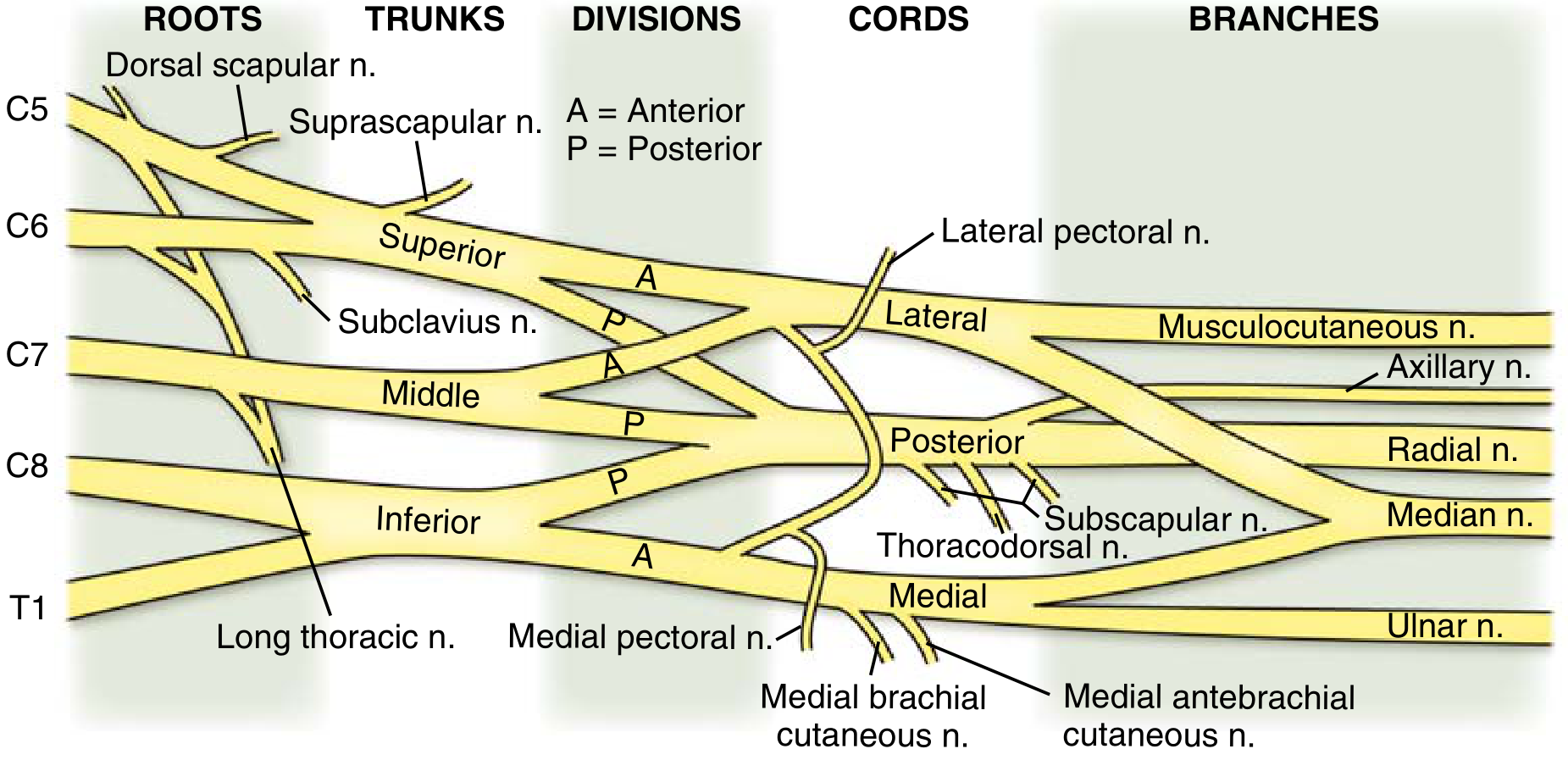
| Level | Components | Key Nerves |
|---|---|---|
| Roots | C5, C6, C7, C8, T1 | Dorsal scapular n. (C5), Long thoracic n. (C5-7) |
| Trunks | Superior (C5-6), Middle (C7), Inferior (C8-T1) | Suprascapular n. from superior trunk |
| Divisions | Each trunk → anterior + posterior division (6 total) | - |
| Cords | Lateral (anterior C5-7), Posterior (posterior all), Medial (anterior C8-T1) | Named by relation to axillary artery |
| Branches | Terminal nerves | Musculocutaneous n. (lateral cord), Axillary n. (posterior cord), Radial n. (posterior cord), Median n. (lateral + medial cords), Ulnar n. (medial cord) |
2. TYPES OF BRACHIAL PLEXUS INJURY
A. By Mechanism
| Type | Description | Prognosis |
|---|---|---|
| Avulsion | Root torn from spinal cord (preganglionic); most severe | No recovery; nerve transfer surgery |
| Rupture | Nerve torn at plexus level but outside cord (postganglionic) | Surgical repair/graft possible |
| Neuroma-in-continuity | Scar tissue at injury site; partial damage | Variable; may need surgical neurolysis |
| Neuropraxia | Conduction block only; axons intact | Full recovery; weeks to 3 months |
B. By Level
| Pattern | Roots Involved | Common Name |
|---|---|---|
| Upper plexus | C5, C6 (sometimes C7) | Erb-Duchenne Palsy |
| Lower plexus | C8, T1 | Klumpke's Paralysis |
| Total plexus | C5-T1 | Complete brachial plexus injury ("flail arm") |
C. By Cause
| Cause | Mechanism | Population |
|---|---|---|
| Obstetric/birth injury | Traction during delivery | Neonates |
| High-velocity trauma | Motor vehicle accident, motorcycle crash | Young adults |
| Stretch/traction | Forceful shoulder depression away from neck | Adult trauma |
| Penetrating injury | Gunshot, stab | Any |
| Iatrogenic | Surgery (median sternotomy, shoulder arthroscopy) | Surgical |
| Neoplastic | Pancoast tumour (lung apex); metastatic breast cancer | Cancer patients |
| Radiation | Post-radiation fibrosis (breast/lymphoma Rx) | Cancer survivors |
3. CLINICAL EVALUATION OF BRACHIAL PLEXUS INJURY
- Mechanism: traction? penetrating? birth? velocity?
- Onset: immediate (neurotmesis) vs. delayed (haematoma compression)
- Progress: improving = neuropraxia/axonotmesis; static = severe injury
- Motor assessment: MMT of all upper limb muscle groups to localize level
- Sensory assessment: Semmes-Weinstein, two-point discrimination, dermatomal mapping
- Tinel's sign: percussion along nerve course; advancing Tinel = regeneration
- Horner's syndrome (ptosis, miosis, anhidrosis, enophthalmos): indicates T1 root avulsion (sympathetic fibers)
- Winging of scapula: long thoracic nerve (C5-7) involvement
- EMG/NCS: after 3-4 weeks (Wallerian degeneration complete); determines level, severity, and signs of reinnervation
- MRI of brachial plexus: identifies avulsion (pseudomeningocele), tumour, fibrosis
- CT myelogram: gold standard for detecting root avulsions
4. SURGICAL MANAGEMENT
- Nerve repair (primary neurorrhaphy): immediate for clean lacerations
- Nerve grafting: sural nerve bridges gaps >3 cm
- Nerve transfer (neurotisation): sacrifices a less important nerve to restore critical function (e.g., intercostal nerves → musculocutaneous nerve to restore elbow flexion)
- Tendon transfers: for late/incomplete recovery - redistribute functioning muscle power
- Free functional muscle transfer: e.g., gracilis muscle to restore elbow flexion
5. OT MANAGEMENT OF BRACHIAL PLEXUS INJURY
Pre-operative OT
- Baseline ROM, MMT, sensory assessment, functional assessment
- Patient education: recovery timeline (nerve regeneration ~1 mm/day)
- Prevent complications: anti-deformity splinting, joint ROM maintenance
- Psychological preparation: adjusting to potential long-term impairment
Post-operative and Ongoing OT
A. Splinting and Positioning
- Shoulder subluxation support: sling or humeral cuff to prevent inferior subluxation when deltoid is paralysed
- Elbow extension splint: maintain extension if elbow flexors recovering; prevent flexion contracture
- Wrist cock-up splint: if wrist extensors paralysed
- Anti-claw splint (lumbrical bar): if intrinsic hand muscles paralysed
- Resting hand splint: positions hand in functional/safe position during flaccid phase
B. Maintaining Joint Range of Motion
- Passive ROM to all joints in affected upper limb - daily, multiple sessions
- Prevents contractures which would limit function even after nerve recovery
- Particular vigilance: shoulder external rotation and abduction (rapidly contract)
- Patient and family taught home passive ROM programme
C. Strengthening and Motor Re-education
- As motor recovery begins (Tinel advances; EMG shows nascent units):
- Facilitation techniques: electrical stimulation, biofeedback, tapping, stretch
- Graded active-assisted → active exercises
- Functional activity: task-specific training (reaching, grasping)
- Mirror therapy: particularly for total plexus injury
D. Sensory Re-education
- Protective sensation returns first (S2-S3 on MRC sensory scale)
- Phase I: localization training (eyes open → closed; patient identifies where touched)
- Phase II: discriminative training - textures, shapes, stereognosis
- Desensitization: for hypersensitive areas during re-innervation
E. Functional and ADL Retraining
- One-handed techniques and equipment: for period of motor paralysis
- Compensatory strategies: use of proximal intact function (shoulder shrug for hand placement in total plexus)
- Environmental adaptations: stabilize objects, use dycem mats, Velcro, built-up handles
- For severe/permanent deficit: vocational rehabilitation, assistive technology
F. Pain Management
- Neuropathic pain is common and often severe in plexus injury (especially avulsion)
- OT role: desensitization, graded sensory input, TENS, mirror therapy, graded motor imagery
- Meaningful occupation provides distraction and improves pain self-efficacy
- Refer for medical/pharmacological pain management (pregabalin, amitriptyline) as appropriate
G. Psychosocial Support (Bruce & Borg; Creek & Lougher)
- Brachial plexus injury often affects young adults with major occupational/vocational impact
- Adjustment disorder, depression, and anxiety are common
- Role disruption: worker, parent, athlete, musician
- OT uses MOHO framework: rebuild volition, reconstruct habitual routines, modify environment
- Peer support; return to education/work planning
G. Erb's Palsy (Erb-Duchenne Paralysis)
1. DEFINITION AND CAUSE
- Adults: fall of weight on shoulder; motorcycle accident where head is moved forcefully away from shoulder (excessive depression of shoulder + lateral neck tilt)
- Obstetric/Neonatal (Obstetric Brachial Plexus Palsy - OBPP): difficult labour; shoulder dystocia; the angle between shoulder and neck is "opened out" - excessive traction on superior trunk
2. MUSCLES AFFECTED (C5-C6)
| Muscle | Action Lost |
|---|---|
| Deltoid | Shoulder abduction |
| Biceps brachii | Elbow flexion, forearm supination |
| Brachialis | Elbow flexion |
| Brachioradialis | Elbow flexion |
| Supraspinatus | Shoulder abduction initiation |
| Infraspinatus | External rotation of shoulder |
| Supinator | Forearm supination |
| Teres minor | External rotation |
3. CHARACTERISTIC POSTURE - "WAITER'S TIP" / "POLICEMAN'S TIP"
- Shoulder: adducted, internally rotated (unopposed by paralysed abductors and external rotators)
- Elbow: extended (paralysed biceps/brachialis)
- Forearm: pronated (unopposed pronators; supinator paralysed)
- Wrist and fingers: may be slightly flexed but generally spared (if C7 involved, wrist extension also weak)
4. SENSORY LOSS
- Over the outer aspect of the arm (lateral arm: axillary nerve - C5 dermatome)
- Upper lateral forearm (musculocutaneous nerve - C6 dermatome)
- Thumb and index finger sensory changes (C6 dermatome)
5. OT MANAGEMENT OF ERB'S PALSY
In Adults (Post-Traumatic)
- Sling/shoulder support: prevents inferior subluxation of glenohumeral joint (deltoid paralysed)
- Passive ROM: daily passive shoulder abduction, external rotation, elbow flexion/extension, forearm supination
- Critical: prevent posterior shoulder capsule contracture (which would limit external rotation even after recovery)
- Elbow flexion splint/resting splint: maintain elbow and shoulder in functional position if needed
- Motor re-education: electrical stimulation, tapping, vibratory input to recovering muscles
- Facilitation techniques: PNF (Proprioceptive Neuromuscular Facilitation) - especially diagonal patterns engaging C5/C6 muscles
- Progressive AROM exercises: shoulder abduction, external rotation; elbow flexion; supination
- Biofeedback for muscle re-education
- Functional tasks: reaching, overhead activities, throwing, dressing
- Adapted dressing techniques during flaccid phase (one-handed methods)
- Return to bilateral upper limb activities as function returns
- Work simulation specific to patient's occupation
In Neonates/Children (Obstetric Brachial Plexus Palsy) (Case-Smith; Kramer & Hinojosa)
- Toronto Score / Mallet Classification: classifies shoulder and elbow function
- Active Movement Scale (AMS): graded assessment of movement against gravity for neonates
- Developmental assessment: impact on gross and fine motor milestones
- Passive ROM exercises: taught to parents from birth - shoulder external rotation and abduction, elbow flexion, forearm supination
- Most important: prevent internal rotation contracture of shoulder and elbow flexion contracture
- Positioning: place toys on affected side to encourage reaching; facilitate tummy time to promote shoulder girdle use
- Splinting: rarely used in neonates acutely; later static progressive splints if contracture develops
- Parent education: central role - parents are the primary therapists at home
- Serial splinting: for developing contractures (elbow, shoulder)
- School-age children: handwriting aids, ADL adaptations, sport modifications, psychological support
- Nerve repair/grafting
- Post-surgical OT: immediately resume passive ROM; progress to active exercises as reinnervation occurs; long-term sensory re-education
H. Klumpke's Paralysis (Déjerine-Klumpke Paralysis)
1. DEFINITION AND CAUSE
- Neonatal: breech presentation with arms above the head - forceful abduction of shoulder
- Adults: person falling clutches at an object above; someone failing to obtain a foothold on a moving bus forcefully hyperabducts the arm - the inferior trunk is stretched from below
- Less common than Erb's palsy
2. MUSCLES AFFECTED (C8-T1)
- All interossei (dorsal and palmar)
- All hypothenar muscles (abductor, flexor, opponens digiti minimi)
- All thenar muscles (opponens, abductor, flexor pollicis brevis - deep head)
- All lumbricals
- Long digital flexors (FDP to all fingers - C8) and FPL if C8 involved
- Wrist flexors (FCU primarily)
3. CLINICAL FEATURES
- Claw hand (main en griffe): hyperextension at all MCPs + flexion at all IPs - because ALL intrinsic muscles paralysed (unlike ulnar lesion which spares median-innervated lumbricals to index and middle fingers)
- Loss of all hand grip and pinch
- Wrist flexion weakness (FCU)
- If C8 also involved: loss of long digital flexors → completely flail fingers
- Inner (medial) aspect of forearm (medial antebrachial cutaneous nerve - T1)
- Hand medial border (C8)
- Inner 1.5 fingers (ring and little finger - C8/T1)
- Ptosis (drooping upper eyelid)
- Miosis (constricted pupil)
- Enophthalmos (sunken eyeball)
- Anhidrosis (absence of sweating on same side of face)
- Presence of Horner's indicates preganglionic/root avulsion - very poor prognosis for spontaneous recovery
4. COMPARISON: ERB'S vs. KLUMPKE'S vs. TOTAL PLEXUS
| Feature | Erb's Palsy (C5-C6) | Klumpke's Palsy (C8-T1) | Total Plexus (C5-T1) |
|---|---|---|---|
| Level | Upper plexus | Lower plexus | Entire plexus |
| Mechanism | Shoulder depression + head away | Hyperabduction of shoulder | High-velocity trauma |
| Deformity | "Waiter's tip" - shoulder adducted/IR, elbow extended | Claw hand (all intrinsics); flail hand | Flail arm |
| Shoulder | Paralysed | Intact | Paralysed |
| Elbow | Cannot flex | Can flex (biceps C5-6 intact) | Paralysed |
| Wrist/Hand | Intact or mild | Severely paralysed | Completely paralysed |
| Sensory loss | Lateral arm/forearm, thumb/index | Medial forearm, hand, ring/little fingers | Entire arm |
| Horner's | Absent | Present (if T1 avulsion) | Often present |
| Prognosis | Better | Poor if Horner's present | Variable; avulsion = worst |
5. OT MANAGEMENT OF KLUMPKE'S PARALYSIS
A. Splinting
- Blocks MCP hyperextension → allows long extensors to extend IPs → functional improvement immediately
- Worn during functional activities
- Can be made in thermoplastic material
- Safe/functional position: MCPs 70-90° flexion, IPs straight, thumb abducted
- Prevents fixed contractures during flaccid phase
- Worn at night; alternated with active programme during day
- Maintains thumb in abduction/opposition (thenar muscles paralysed)
- Enables basic lateral pinch and functional grasp
B. Passive ROM Maintenance
- All finger MCP flexion exercises (to prevent hyperextension contracture)
- All finger IP extension exercises
- Thumb web space stretching (to prevent adduction contracture)
- Wrist ROM maintenance
C. Sensory Re-education
- Critical: medial hand sensory loss includes ring and little fingers - important for grasp safety
- Protection education: patient must visually monitor affected hand for injury
- Gradual sensory re-education as recovery occurs
D. Functional Retraining
- One-handed ADL techniques with non-affected arm during flaccid phase
- As recovery occurs: graded functional activities - grip, pinch, manipulation
- Writing aids, built-up handles, key adapters for precision tasks
- Bimanual activity practice: use remaining proximal function (elbow flexion, shoulder) in conjunction with recovering hand
E. Horner's Syndrome Management
- Ptosis: if significant, refer ophthalmology; functional task modifications for visual field limitations
- Anhidrosis: educate about temperature regulation needs on affected face side
- Psychological support: Horner's indicates severe injury; realistic expectations
F. Psychosocial Support (Bruce & Borg; Creek & Lougher)
- Klumpke's predominantly affects hand function - most disabling for ADL, work, and fine motor leisure
- Address grief about hand loss; occupational identity disruption
- Vocational rehabilitation planning: keyboard adaptations, work tools, potential role changes
- Return to meaningful leisure: musical instruments, crafts, sports - with adaptations
Summary: Comparison of OT Interventions
| Condition | Primary Splint | Main OT Focus | Key Precaution |
|---|---|---|---|
| Brachial plexus (total) | Shoulder sling + resting hand | Prevent contractures; one-handed ADL; graded recovery | Shoulder subluxation; shoulder ROM |
| Erb's palsy (C5-C6) | Shoulder sling; elbow brace | Shoulder ROM; external rotation; elbow flexion recovery | Internal rotation contracture prevention |
| Klumpke's (C8-T1) | Anti-claw splint + opponens splint | Hand ROM; sensory protection; fine motor recovery | Horner's = poor prognosis; MCP hyperextension contracture |
| Total (obstetric) | Parent-taught passive ROM; rarely splinted | Parent education; developmental facilitation; functional play | Shoulder internal rotation + adduction contracture |
- Pedretti's Occupational Therapy: Practice Skills for Physical Dysfunction, Pendleton & Schultz-Krohn
- Occupational Therapy for Physical Dysfunction, Radomski & Trombly
- Occupational Therapy and Physical Dysfunction, Turner, Foster & Johnson
- Willard & Spackman's Occupational Therapy
- S Das Manual on Clinical Surgery (13th ed.) - Brachial Plexus chapter (Erb-Duchenne, Klumpke)
- Miller's Review of Orthopaedics (9th ed.) - Brachial Plexus Anatomy and Erb's Palsy
- Bradley and Daroff's Neurology in Clinical Practice - Stretch/Traction injuries, waiter's tip
- Color Atlas of Human Anatomy - Lower Brachial Plexus (Klumpke's)
- OT and Mental Health, Creek & Lougher; Mental Health Concepts, Early; Frames of Reference in Psychosocial OT, Bruce & Borg
- OT for Children, Case-Smith; Frames of Reference for Pediatric OT, Kramer & Hinojosa
OT IN MEDICAL CONDITIONS Detailed and researched article on: Objectives and role of Occupational Therapy in: a. Rheumatoid arthritis b. Leprosy c. Cardiac dysfunctions d. Complications pf Diabetes Mellitus e. Geriatric conditions g. Chronic obstructive pulmonary diseases h. HIV & ADS i. Haemophilia j. Palliative care k. SLE l. Obesity m. Thalassemia n. Asthma, tuberculosis o. pneumonia and covid p. breathing exercise q. gerontology and Geriatric conditions r. oncological rehabilitation Recommended book(s) for Reference: 1. Pedretti’s Practice skills for physical dysfunction edited by Heidi McHugh Pendleton ,Winifred Schultz Krohn 2. Occupational Therapy for Physical Dysfunction by Mary Vining Radomski, Catherine A Trombly 3. Occupational Therapy and Physical Dysfunction, Principles, Skills and Practice by Ann Turner, Margaret Foster, Sybil E Johnson 4. Introduction to Occupational Therapy by Hussey Subonis ,Chafea O Brien 5. Occupational Therapy and Mental Health edited by Jennifer Creek, Lesley Lougher 6. Mental Health Concepts and Techniques for the Occupational Therapy Assistant by Mary Beth Early 7. Frames of Reference in Psychosocial Occupational Therapy by Mary Ann Bruce, Barbara Borg 8. Willard & Spackman’s Occupational Therapy 9. Occupational Therapy for children by Jane Case Smith 10. Frames of Reference for Pediatric Occupational Therapy by Paula Kramer , Jim Hinojosa
rheumatoid arthritis hand deformity ulnar deviation swan neck boutonniere
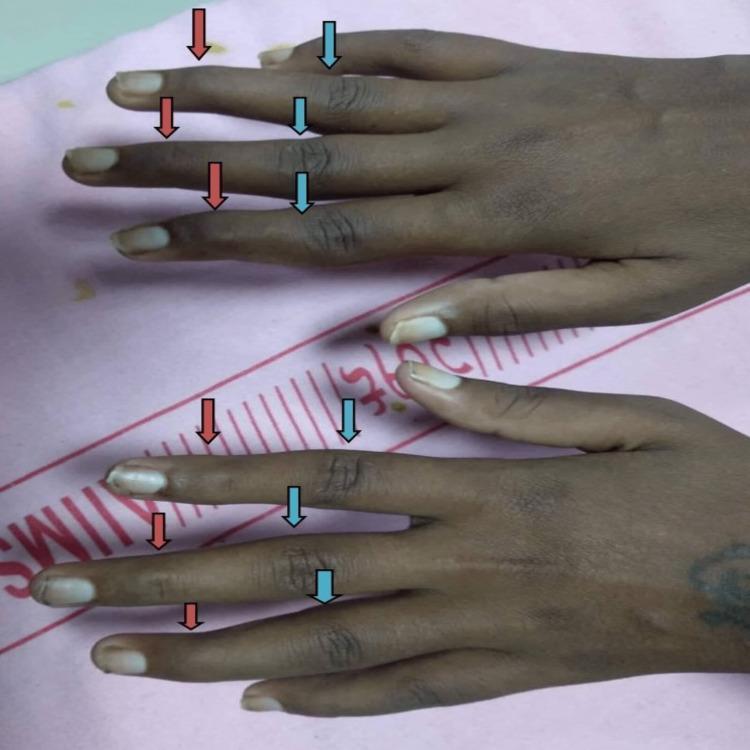
A clinical photograph of both hands from a dorsal view, demonstrating characteristic musculoskeletal deformities associated with systemic lupus erythematosus (SLE) or rheumatoid arthritis. The image highlights a classic swan-neck deformity pattern in multiple fingers. Blue arrows indicate hyperextension at the proximal interphalangeal (PIP) joints, while red arrows indicate compensatory flexion at the distal interphalangeal (DIP) joints. Additionally, there is evidence of ulnar deviation of the fingers at the metacarpophalangeal (MCP) joints, where the digits angle toward the ulnar side of the hand. This visual representation serves to teach diagnostic physical exam findings in rheumatology, specifically illustrating Jaccoud's arthropathy or similar non-erosive/erosive arthropathies. The skin also shows signs of pallor, consistent with the clinical context of systemic autoimmune disease.
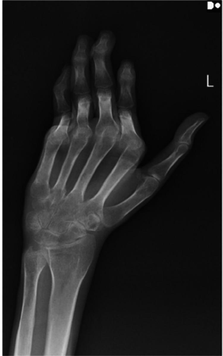
This diagnostic image is a posterior-anterior (PA) radiograph of the left hand and wrist. The primary finding is significant joint malalignment characterized by ulnar deviation at the metacarpophalangeal (MCP) joints and various deformities of the interphalangeal joints, including swan-neck and boutonniere-like appearances. Notably, despite the severe subluxation and deviation, the bony structures demonstrate a striking absence of marginal erosions or significant joint space narrowing, which are typical hallmarks of erosive inflammatory arthritis. The carpal bones, metacarpals, and phalanges maintain relatively normal bone density and cortical integrity. This presentation is highly characteristic of Jaccoud arthropathy, a non-erosive, reducible joint deformity often associated with connective tissue diseases like Systemic Lupus Erythematosus (SLE) or Mixed Connective Tissue Disease (MCTD). The image serves as an educational example to differentiate non-erosive mechanical deformities from erosive pathologies like Rheumatoid Arthritis.
leprosy disability hand claw foot drop rehabilitation
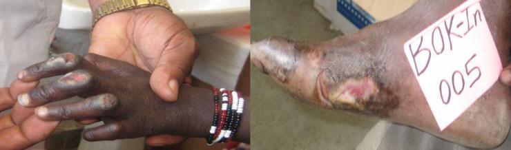
Two-panel clinical photograph demonstrating World Health Organization (WHO) Grade 2 Disability (G2D) in patients with leprosy. The left image shows advanced digital involvement of the hand, characterized by finger shortening (autoresorption), muscle wasting, and chronic ulcerations on the distal phalanges. Skin hyperpigmentation and tissue contractures are visible, typical of prolonged anesthetic nerve damage. The right image depicts a human foot with a large, chronic plantar-lateral ulcer featuring exposed subcutaneous tissue, surrounding erythema, and peripheral hyperpigmentation. A medical identifier tag is visible. These findings illustrate the severe musculoskeletal and integumentary complications of late-stage leprosy (Hansen’s disease), resulting from peripheral neuropathy and secondary trauma to insensate limbs.
This clinical photograph captures bilateral hands showing claw hand deformity due to early peripheral nerve involvement from tuberculoid leprosy. The flexion contractures of the fingers result from intrinsic muscle wasting (interosseous muscles, thenar, and hypothenar groups) secondary to chronic neuritis with thickened nerves. The palmar aspect highlights impaired intrinsic function with partial lumbrical loss creating a characteristic posture: hyperextension at the metacarpophalangeal joints with flexion of the interphalangeal joints, and evident weakness in grip and dexterity. Nerves involved are classically thickened and tender in Hansen's disease, often involving the ulnar nerve predominantly with contribution from the median nerve. Clinically, this finding signals early sensory-motor neuropathy and potential progression to disability if untreated. The image is a color clinical photograph from Global Skin Atlas, credited to Dr. Ian McColl, illustrating public health relevance of leprosy neuropathy in endemic regions. Notably, the thumbs and other digits may appear relatively spared initially while intrinsic hand muscles disproportionately atrophy. This deformity is important for differential diagnosis against traumatic ulnar neuropathy, diabetic neuropathy, and other causes of clawing. It informs functional prognosis, guides nerve function assessment, and supports educational depiction of Hansen's disease nerve involvement for medical trainees and researchers.
pursed lip breathing diaphragmatic breathing COPD pulmonary rehabilitation
A clinical photograph depicting a patient education session for pulmonary rehabilitation. The image shows a female patient in a seated, upright posture on an examination bench, demonstrating pursed-lip breathing (PLB) under the guidance of a healthcare professional. The patient is shown with lips rounded and puckered as during the exhalation phase of the technique, which is used to reduce work of breathing, increase airway pressure, and prevent bronchial collapse in obstructive lung diseases or systemic conditions with pulmonary involvement such as Systemic Lupus Erythematosus (SLE) and Lupus Nephritis (LN). To the right, a healthcare provider, wearing a white clinical coat, disposable gloves, and a surgical mask, observes and instructs the patient. The setting is a clinical or physiotherapy environment, illustrating a non-pharmacological intervention for managing chronic breathlessness (dyspnea) and improving respiratory efficiency. This visual is designed for educational purposes to demonstrate proper breathing mechanics and the patient-provider interaction during functional respiratory training.
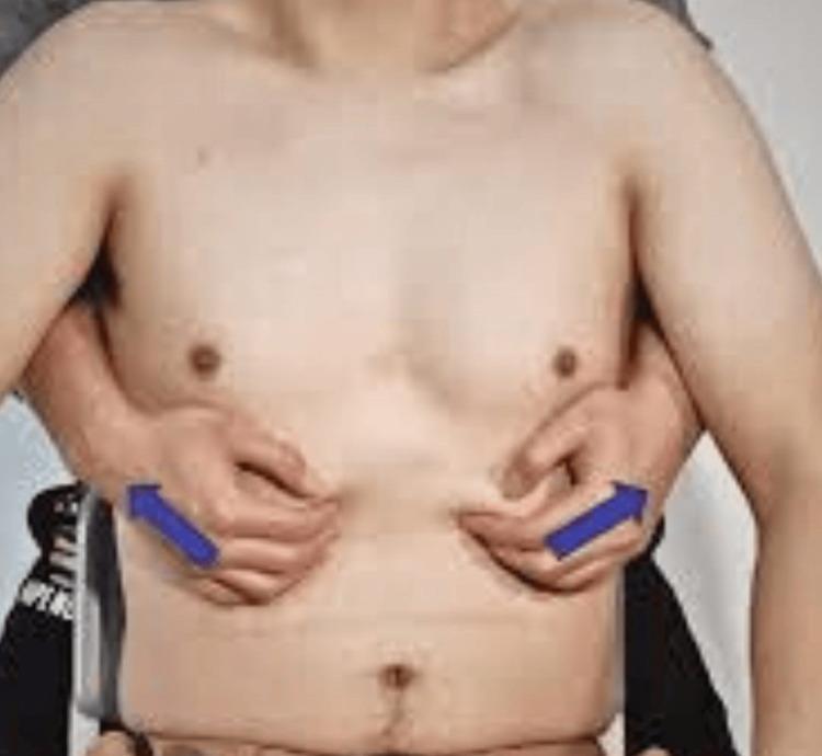
This clinical photograph demonstrates a manual therapy technique identified as diaphragmatic stretching, commonly utilized in pulmonary rehabilitation for patients with chronic obstructive pulmonary disease (COPD). The image depicts a practitioner's hands positioned on the lower lateral aspects of a male subject's rib cage, specifically targeting the costal margins. The thumbs and fingers are shown gripping the skin and underlying subcutaneous tissue, with blue directional arrows indicating a bilateral, lateral-outward stretching motion. Key visible anatomical landmarks include the inferior rib cage, epigastric region, and umbilicus. The procedure is designed to improve thoracic mobility, reduce respiratory muscle tension, and facilitate better diaphragmatic excursion. This visual serves as an educational guide for physical therapy, osteopathic manipulative treatment, and respiratory care students to understand hand placement and vector of force for mobilizing the lower thoracic cage and myofascial structures surrounding the diaphragm.
diabetic foot ulcer neuropathy peripheral vascular care prevention
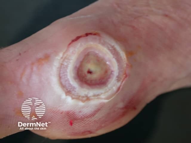
Clinical photography of a plantar foot ulcer with features typical of a neuropathic ulcer in peripheral neuropathy. The image shows a circular to oval dermal lesion on the plantar aspect of the foot with a pale, necrotic to sloughy central area surrounded by a blurred pink to red halo. The wound base appears relatively dry with minor granulation tissue, and a thick callus rim encircles the ulcer margins. Surrounding skin is mildly inflamed, with faint erythema and tiny fissures at the periphery; edema is modest. The lesion is shallow to moderate in depth, penetrating through the epidermis and extending into superficial dermal layers in places, consistent with non-ischemic, neuropathic pathology. The clinical presentation reflects reduced protective sensation and repetitive minor trauma, typical of diabetic neuropathy or other sensorimotor neuropathies. Management implications include offloading, meticulous wound debridement, moisture-balanced wound dressings, and infection surveillance. Differential diagnoses include venous stasis ulcer, arterial (ischemic) ulcer, pressure ulcer, or infectious wound, but the characteristic location, shape, callus rim, and neuropathic risk factors favor diabetic neuropathic ulcer. Clinically relevant correlations include diabetes mellitus status, peripheral neuropathy assessment, vascular evaluation, and serial wound measurement to monitor healing. This image is educational for dermatology, podiatry, endocrinology, wound care teams, and medical training in wound assessment and offloading strategies.
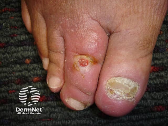
This is a high-resolution clinical photograph of a diabetic foot ulcer located on the toe, captured with visible light in a close-up dorsal view. The lesion appears on the dorsal aspect of the toe with a circular to oval ulcer base, demonstrating a pink to red granulation core surrounded by a yellow crust and a thick hyperkeratotic rim. The surrounding skin shows diffuse edema and callus formation, consistent with chronic pressure and neuropathic changes seen in diabetes mellitus. The nail plate is absent or dystrophic at the affected digit. The wound margins are defined but may show shallow undermining, with surrounding erythema indicating localized inflammation. No visible purulence is evident, but slough or crust may obscure depth. This presentation is characteristic of diabetic foot ulcers, which arise from neuropathy reducing protective sensation and repetitive trauma, often in combination with peripheral vascular disease. Clinically, such ulcers require offloading, meticulous wound cleaning and debridement, infection surveillance, glycemic control, and evaluation for osteomyelitis in deeper involvement. Imaging and lab correlation may include vascular assessment, Doppler studies, wound swab cultures, and CBC. The image serves educational purposes in dermatology, podiatry, and wound care training, illustrating management principles for DFU staging, local wound care, and prevention of complications.
OT in Medical Conditions
Detailed Article: Objectives and Role of Occupational Therapy
a. RHEUMATOID ARTHRITIS (RA)
Overview
OT Objectives
- Protect joints from excessive mechanical stress
- Maintain functional ROM and prevent deformity
- Manage pain and fatigue
- Preserve and restore ADL independence
- Provide adaptive equipment and environmental modification
- Educate on self-management and disease monitoring
Key OT Evaluation
- ROM and deformity assessment: Goniometry - document swan-neck, boutonnière, ulnar deviation, MCP subluxation, Z-deformity of thumb
- Hand function: Grip and pinch strength (Jamar, pinch gauge)
- Disease activity: HAQ (Health Assessment Questionnaire) - ADL-specific RA measure; DAS28 awareness
- COPM: Patient's occupational priorities
- Pain: VAS, numeric rating scale
- Fatigue: Multidimensional Assessment of Fatigue (MAF)
OT Interventions
1. Joint Protection Principles
- Respect pain: pain beyond 1 hour after activity signals that activity was too demanding - modify
- Maintain ROM: use muscles and joints through full ROM daily, but avoid sustained end-range positions
- Avoid positions of deformity: avoid ulnar deviation forces (e.g., turning doorknobs towards ulnar side), avoid sustained pinch/grip with thumb
- Use the largest/strongest joint: carry bags on forearm not in fingers; push up with palm not fingers
- Avoid sustained grip: alternate grip with rest; use built-up handles to reduce pinch force
- Avoid lifting with finger flexion only: use both hands; use palmar surface
- Distribute load: spread load across multiple joints; use two hands instead of one
- Balance work and rest: alternate activity with rest; take microbreaks
2. Energy Conservation (4 Ps)
- Pace: slow down; build rest into schedule; "work smarter not harder"
- Plan: organise tasks to minimize effort; eliminate unnecessary steps
- Prioritize: rank tasks by importance; delegate secondary ones
- Position: sit to work; keep items at accessible height
3. Splinting
- Resting hand splint: during flares - positions wrist, MCPs, and IPs in functional alignment; reduces inflammation; worn at night
- Working wrist splint (wrist cock-up): worn during activity to support wrist and reduce pain
- MCP ulnar deviation splint: applies radial corrective force to MCP joints; reduces pain during activities
- Thumb CMC splint (short opponens): for basal joint arthritis; reduces pinch stress
4. Adaptive Equipment and Assistive Technology
- Built-up handles: pencils, cutlery, toothbrush (reduces pinch force)
- Jar opener, lever taps, electric can opener
- Rocker knife: reduces force of cutting
- Button hook, long-handled shoe horn, sock aid: reduces fine motor demands of dressing
- Velcro fastenings: replace buttons
- Raised toilet seat, bath rail: reduce joint stress with transfers
- Key turner: reduces torque force on finger joints
- Computer adaptations: voice recognition, ergonomic keyboard/mouse
5. Exercise
- Active ROM exercises: daily range through available motion to prevent contractures
- Gentle strengthening (when inflammation controlled): isometric, then isotonic
- Hydrotherapy: warm water reduces pain and resistance; excellent for ROM exercise
- Avoid high-impact, high-resistance exercise during active flare
6. Education and Self-Management
- Disease process, medication effects, monitoring signs of flare
- Joint protection incorporation into daily routines
- When to seek medical review
- Self-monitoring tools (joint count, morning stiffness duration)
7. Psychosocial Support (Creek & Lougher; Bruce & Borg)
- Chronic pain, fatigue, and functional loss cause depression and anxiety in up to 40% of RA patients
- Occupational identity: RA threatens roles as parent, worker, homemaker
- MOHO-based intervention: rebuild habits and routines around modified capabilities
- Cognitive-Behavioural approaches: pain catastrophizing, activity avoidance cycle
- Peer support groups; self-management programmes (Stanford Arthritis Self-Management Program)
b. LEPROSY (HANSEN'S DISEASE)
Overview
Nerve Involvement and Resulting Disabilities
| Nerve Affected | Motor Loss | Sensory Loss | Deformity |
|---|---|---|---|
| Ulnar nerve | Interossei, hypothenar, ring/little lumbrical | Medial hand, ring/little fingers | Claw hand (ring/little fingers) |
| Median nerve | Thenar muscles | Palmar surface, thumb/index/middle | Ape hand; impaired precision grip |
| Radial nerve | Wrist/finger extensors | Dorsoradial hand | Wrist drop |
| Common peroneal | Ankle/toe dorsiflexors | Dorsum of foot | Foot drop |
| Posterior tibial | Intrinsic foot muscles | Plantar foot | Clawed toes; insensate plantar foot |
| Facial nerve | Orbicularis oculi | - | Lagophthalmos (inability to close eye) |
OT Evaluation
- WHO disability grading: Grade 0 (no impairment) → Grade 1 (anaesthesia) → Grade 2 (visible deformity)
- Voluntary Muscle Testing (VMT): strength of affected muscles
- Sensory assessment: ball-tipped pen testing (0-4 scale); Semmes-Weinstein monofilaments
- Eye inspection: lagophthalmos, incomplete blink, corneal sensation
- Self-care ability: ADL assessment
OT Interventions
1. Prevention of Disability (Grade 0-1)
- Protective sensation education: since limbs are insensate, patient must visually inspect daily
- Soaking and oiling: daily foot/hand soak in water + application of oil to prevent cracks (cracked skin = entry for infection)
- Inspection education: check shoes before wearing; inspect hands after activities; check for blisters
- Shoe modifications: microcellular rubber (MCR) footwear to distribute plantar pressure; rocker sole; moulded insoles
2. Management of Established Deformity
- Anti-claw splint (lumbrical bar): blocks MCP hyperextension → enables IP extension → functional grasp
- Knuckle-bender splint: for PIP flexion contracture
- Tendon transfer surgery referral: FDS to intrinsic transfer (correction of claw) - post-surgical OT vital
- Passive ROM maintenance: prevent contractures
- Cock-up wrist splint: positions wrist for functional use
- Dynamic wrist extension splint
- Foot-drop correction brace / AFO (Ankle-Foot Orthosis): dorsiflexion assist
- Gait training
- Eye closure exercises (manually close eye with finger if unable)
- Dark glasses: protect from dust and sunlight
- Tarsal lubricants and moisture chamber spectacles: prevent corneal damage
- Refer to ophthalmology for tarsorrhaphy if corneal involvement
3. Self-Care (Activities of Daily Living)
- Adapted grip techniques for insensate hands
- Modified tools: thicker handles, padded grips
- Protective gloves for work
4. Wound and Ulcer Management
- Plantar ulcers: offloading is the primary intervention (total contact cast, padded footwear); wound dressing
- Regular wound assessment and referral
5. Psychosocial Rehabilitation (Creek & Lougher; Early)
- Leprosy carries profound stigma - social isolation, loss of employment, family rejection
- OT facilitates social reintegration: supported community activities, vocational training
- Livelihood rehabilitation: skills training for modified occupations with disability
- Group work with other leprosy-affected persons reduces stigma and isolation
- Advocacy for anti-discrimination rights
c. CARDIAC DYSFUNCTIONS
Conditions Addressed
- Congestive Heart Failure (CHF)
- Ischaemic heart disease / Coronary artery disease (CAD)
- Myocardial infarction (MI) - acute and recovery
- Valvular disease
- Arrhythmias
- Cardiomyopathy
OT Objectives
- Grade functional activity safely using MET levels
- Teach energy conservation and work simplification
- Prevent deconditioning while avoiding overexertion
- Facilitate return to occupational roles
- Educate on activity monitoring and warning signs
- Support psychosocial adjustment to chronic cardiac disease
Key Assessments
- 6-Minute Walk Test (6MWT): functional capacity
- MET estimation: prior functional level and current capacity
- Borg RPE Scale (6-20): perceived exertion guide for activity
- NYHA Class (New York Heart Association): I-IV functional classification
- Barthel Index / FIM: ADL baseline
- Fatigue and dyspnea scales: Borg Dyspnea Scale, mMRC
MET-Based Activity Guide
| NYHA Class | METs Tolerated | ADL Examples | OT Focus |
|---|---|---|---|
| I (No limitation) | >7 METs | Full independence | Risk factor education; maintenance |
| II (Slight limitation) | 4-6 METs | Normal ADL; moderate exertion limits | Energy conservation; graded activity |
| III (Marked limitation) | 2-4 METs | Limited to light ADL | Extensive energy conservation; adaptive equipment |
| IV (Symptoms at rest) | <2 METs | Bedrest, basic self-care only | Functional positioning; dignity-preserving care; caregiver training |
OT Interventions
1. Energy Conservation (critical for CHF, Class III-IV)
- The 4 Ps: Pace, Plan, Prioritize, Position
- Sit for all activities possible
- Organise frequently used items at waist height
- Avoid Valsalva maneuver (increases cardiac preload)
- Exhale on exertion; never hold breath
2. Activity Grading
- Introduce activities at appropriate MET level
- Monitor HR, BP, SpO2, RPE before/during/after
- Progress gradually; watch for decompensation
3. ADL Retraining
- Bathing: seated shower; bath board; handheld shower
- Dressing: seated; adapted fasteners; dressing sequence to minimize exertion
- Meal preparation: seated cooking; lightweight appliances; rest between tasks
4. Sexual Activity Education
- Generally safe when patient can climb two flights of stairs without symptoms
- Position guidance: side-lying or partner on top (less cardiac demand)
5. Return to Work
- Job demands analysis
- Phased return; modified duties
6. Psychosocial (Bruce & Borg; Creek & Lougher)
- Depression and anxiety: very prevalent post-MI and in CHF
- Fear of exertion ("cardiac anxiety"): graded exposure with monitoring builds confidence
- Role disruption: breadwinner, parent, athlete
d. COMPLICATIONS OF DIABETES MELLITUS
Overview
- Peripheral neuropathy (sensorimotor, autonomic)
- Diabetic retinopathy and visual impairment
- Nephropathy and renal failure effects
- Diabetic foot disease (neuropathic ulcers, Charcot arthropathy)
- Cardiovascular disease
- Cognitive impairment ("diabetic encephalopathy")
- Amputation (lower limb, upper limb)
OT Objectives
- Prevent secondary complications (pressure injuries, falls, burns, contractures) through education
- Maintain ADL independence despite visual, sensory, and motor impairments
- Facilitate insulin and blood glucose monitoring as independent ADL tasks
- Support safe return to occupational roles
Key Assessments
- Peripheral sensation: Semmes-Weinstein monofilaments (10-g filament for protective sensation); vibration (128 Hz tuning fork); proprioception
- Visual screening: functional vision for ADL (reading medication labels, insulin syringes)
- ROM and strength: lower limb for footwear/ambulation; upper limb for self-care and glucose monitoring
- Cognitive assessment: MoCA (T2DM increases dementia risk)
- ADL assessment: particularly insulin administration, blood glucose self-monitoring, foot care
OT Interventions
1. Diabetic Foot Care and Ulcer Prevention
- Daily foot inspection education: use mirror for plantar surface; check between toes; water temperature testing with elbow
- Protective footwear: well-fitting, cushioned shoes; no bare feet; avoid constricting footwear
- Foot hygiene: wash and dry carefully, especially between toes; moisturize (avoid between toes)
- Nail care: refer to podiatry for regular nail trimming; no self-cutting if vision poor
- Pressure relief: appropriate wheelchair cushion/seating for patients with reduced mobility
2. Self-Management of Diabetes as ADL
- Insulin administration: syringe/pen technique; dose drawing; rotation of injection sites; adapted devices (pen magnifiers, syringe guides)
- Blood glucose monitoring: adapted glucometer (large display, auditory); lancet technique; strip insertion with reduced fine motor
- Hypoglycaemia management: recognizing symptoms; carrying glucose; emergency plan
3. Visual Impairment Adaptations
- Large-print labels; talking glucometers; magnifiers
- Kitchen: contrasting colours, tactile markers on appliances, cut-resistant gloves
- Orientation and mobility: OT/rehabilitation teacher collaboration
4. Neuropathy-Related Safety
- Burns prevention: test bath water temperature; avoid hot water bottles directly on skin
- Pressure injury prevention: regular position changes; appropriate seating cushion; bed positioning
- Fall prevention: remove home hazards; non-slip mats; grab bars; appropriate footwear indoors
5. Amputation Rehabilitation
- Lower limb: prosthetic training coordination with physiotherapy; ADL with prosthesis; home modification
- Upper limb: see amputation section in Plastic Surgery module
6. Cognitive and Self-Management Support
- Simplified medication management systems: blister packs, pill organisers, medication reminders
- Diabetes education: carbohydrate counting, reading food labels, adjusting activity
e. GERIATRIC CONDITIONS / GERONTOLOGY
Overview
Common Geriatric Conditions Addressed by OT
- Falls and fall prevention
- Frailty and sarcopenia
- Dementia (Alzheimer's, vascular, Lewy body)
- Osteoarthritis and osteoporosis
- Stroke (covered in neurology OT)
- Parkinson's disease
- Visual/hearing impairment
- Polypharmacy effects
- Delirium (acute confusional state)
OT Objectives
- Maintain functional independence in ADL and IADL for as long as possible
- Prevent falls and their consequences
- Optimise cognitive function and support those with dementia
- Adapt environment and tasks to functional capacity
- Support carers and families
- Facilitate ageing in place (remaining in own home)
Key Assessments
- Cognitive: MMSE, MoCA, ACE-III, Allen Cognitive Level Screen
- ADL/IADL: Barthel Index, FIM, IADL Scale (Lawton), COPM
- Falls risk: Berg Balance Scale, Timed Up and Go (TUG), POMA (Tinetti)
- Environmental: home visit assessment; hazard identification
- Carer assessment: carer burden, knowledge, skills
- Frailty: Edmonton Frailty Scale, FRAIL Scale
- Depression/anxiety: GDS (Geriatric Depression Scale)
OT Interventions
1. Falls Prevention
- Home hazard removal: loose rugs, poor lighting, cluttered pathways, bathroom hazards
- Home modifications: grab bars (toilet, bath, shower); non-slip mats; raised toilet seat; stair rail; ramp installation advice
- Adaptive equipment: walking aid selection and training (coordination with physiotherapy); bed rail; bath seat
- Activity modification: seated ADL; avoiding reaching overhead; appropriate footwear advice
- Medication review referral: polypharmacy increases falls risk significantly
- Vision referral: uncorrected vision is a major falls risk factor
2. ADL and IADL Maintenance
- Task modification and adaptive equipment for age-related impairments
- Cooking: lightweight equipment; seated preparation; simplified recipes; energy conservation
- Dressing: front-fastening garments; long-handled aids; elastic laces
- Bathing: shower chair; grab bars; handheld shower; bath lift
- Home management: energy conservation; paced domestic tasks; neighbourhood services
3. Dementia Care (Willard & Spackman; Hussey)
- Environmental modifications: labels and cues; consistent layout; reduce clutter; improve lighting; contrast colours (white plate on dark tablecloth)
- Routine and structure: predictable daily schedule reduces confusion and agitation
- Activity engagement: meaningful, achievable, sensory-based activities appropriate to cognitive level (Allen Cognitive Level)
- Communication strategies: simple language, one instruction at a time; visual cues
- Caregiver education: understanding dementia behaviours; safe supervision; handling agitation; preventing caregiver burnout
- Safety: wandering prevention (door alarms, GPS); kitchen safety; fire risk
4. Leisure and Social Participation
- Re-engagement in meaningful leisure (gardening, craft, music, reading aids)
- Community participation: day centres, social groups, volunteer roles
- Technology use: tablets, smartphones for communication and cognitive engagement
5. Home Assessment and Discharge Planning
- Pre-discharge home visit (hospital OT) or community home visit
- Recommend home modifications, equipment, support services
- Coordinate home care packages, meals on wheels, transport
- Liaise with social work, district nursing, GP
6. Psychosocial and Spiritual (Creek & Lougher; Bruce & Borg)
- Loss of roles, independence, and contemporaries creates grief
- Life review and reminiscence therapy: reviewing life's meaningful occupations
- Spiritual occupation: connecting with faith community, nature, art
- End-of-life planning support: advance care planning; maintaining valued occupations through declining capacity
f. CHRONIC OBSTRUCTIVE PULMONARY DISEASE (COPD)
Overview
OT Objectives
- Maximize functional independence within ventilatory limits
- Teach energy conservation and breathing techniques
- Grade activities to safe dyspnoea levels
- Improve quality of life through meaningful occupation
- Support psychological wellbeing (anxiety, depression are common)
Key Assessments
- Dyspnoea: Modified Borg Dyspnoea Scale; mMRC Dyspnoea Scale
- Exercise capacity: 6MWT; Incremental Shuttle Walk Test
- ADL performance: Manchester Respiratory Activities of Daily Living Questionnaire (MRADLQ)
- Quality of life: CAT (COPD Assessment Tool); SGRQ (St George's Respiratory Questionnaire)
- Anxiety/depression: HAD Scale (Hospital Anxiety and Depression Scale)
- SpO2 monitoring: during activity assessment
OT Interventions
1. Breathing Retraining Techniques (Harrison's Principles; Fishman's Pulmonary Diseases)
- Inhale through nose (2 counts); exhale through pursed (kissing) lips (4 counts)
- Creates back-pressure in airways → prevents dynamic airway collapse in emphysema
- Slows respiratory rate; reduces air trapping; improves oxygenation
- Used during all exertional activities and acute dyspnoea
- Patient places one hand on chest, one on abdomen
- Breathe so abdomen rises (not chest) - engages diaphragm rather than accessory muscles
- Reduces work of breathing

- Breathing control (gentle relaxed breathing) → Thoracic expansion exercises (deep slow breaths) → Forced expiration technique/Huff (forced exhalation with open glottis, not coughing) → Cough
- Clears secretions effectively with less effort than coughing
- High side-lying: supported in side-lying, lower lung ventilated
- Forward-lean sitting (elbows on table): fixes shoulder girdle → accessory respiratory muscles used more efficiently
- Standing with arms supported (leaning on wall/counter): same principle
2. Energy Conservation
- Pacing: work at 50-70% of maximum capacity; pause before breathlessness, not after
- Coordinating breath with activity: exhale on effort; breathe in before lifting; never hold breath (Valsalva)
- Reduce task demands: seated ADL; simplify cooking; lightweight equipment; electric appliances
- Environment: organise frequently used items at waist height; avoid carrying heavy loads
- Rest before demanding tasks: wash and dress before breakfast if morning is worst time
3. Activity Grading
- Use Borg Dyspnoea Scale (0-10): target 3-4 ("moderate - somewhat severe")
- Gradually increase activity duration and intensity over weeks
- SpO2 monitoring: target ≥90% during activity
4. Relaxation Techniques
- Progressive muscle relaxation
- Mindfulness-based stress reduction
- Reduces anxiety-driven hyperventilation (very common in COPD)
5. Psychosocial (Creek & Lougher)
- COPD = loss of independence, social participation, hobbies; major grief
- Anxiety and depression: 40-50% prevalence in COPD
- Fear of breathlessness → activity avoidance → deconditioning → worse breathlessness (vicious cycle)
- OT uses graded activity and relaxation to break this cycle
- Social engagement in breathlessness-tolerant activities
- Smoking cessation support: identify occupational triggers for smoking; replacement activities
g. HIV & AIDS
Overview
OT Concerns
| Phase | OT Focus |
|---|---|
| Asymptomatic HIV | Lifestyle, health promotion, fatigue management, work support |
| Symptomatic / AIDS | Fatigue, cognitive impairment, neuropathy, ADL assistance |
| HIV-associated conditions | PCP pneumonia (breathlessness), CNS infections (neurological deficits), wasting syndrome |
| HIV-associated neurocognitive disorder (HAND) | Cognitive rehabilitation, compensatory strategies |
| Advanced AIDS / palliative | Quality of life, meaningful occupation, symptom management |
Key OT Interventions
1. Fatigue Management
- HIV-related fatigue is multifactorial (virus, medication, anaemia, depression)
- Activity pacing; energy conservation; sleep hygiene
- Fatigue diary to identify patterns; schedule demanding tasks for peak energy times
2. Cognitive Rehabilitation (HAND)
- HIV affects frontal lobe and subcortical white matter → attention, memory, executive function, processing speed
- Compensatory strategies: memory aids, checklists, structured routines
- Environmental modification: reduce distractions; simplify task demands
- Medication management support: pill organisers, phone reminders
3. Peripheral Neuropathy Management
- HIV itself and nucleoside reverse transcriptase inhibitors (NRTIs) cause painful peripheral neuropathy
- Desensitization; protective techniques; appropriate footwear; fall prevention
4. Psychosocial (Creek & Lougher; Early)
- Stigma: profound occupational isolation; fear of disclosure; discrimination in employment
- OT supports social reintegration: graded community re-entry; supported employment
- Grief and adjustment: to diagnosis, potential life expectancy changes, loss of roles
- MOHO framework: rebuild volition (reconceptualise life goals), habits (restructure daily routine), environmental (navigate discriminatory environments)
- Mental health: depression, anxiety, PTSD common; therapeutic occupation as adjunct to psychological support
5. Work and Role Maintenance
- Supported employment strategies; workplace disclosure decision support
- Ergonomic adaptations for fatigue and neuropathy
- Return to work after opportunistic infections
6. Children with HIV (Case-Smith)
- Developmental assessment and support
- School re-entry; disclosure management with family
- Age-appropriate medication adherence support
h. HAEMOPHILIA
Overview
OT Objectives
- Protect joints from repeated trauma causing haemarthroses
- Manage acute joint bleeding episodes
- Rehabilitate chronic haemophilic arthropathy
- Maintain ADL independence
- Educate on activity modification and safety
Key Problems
| Complication | OT Relevance |
|---|---|
| Haemarthrosis | Acute joint pain, swelling, restricted ROM; most common joints: knee, elbow, ankle |
| Haemophilic arthropathy | Chronic synovitis → cartilage destruction → joint contracture, pain, loss of ROM |
| Muscle haematoma | Pain, compartment syndrome risk; reduced mobility |
| Target joints | Repeatedly affected joints with progressive damage |
| Inhibitors | Antibodies to factor concentrate; more difficult treatment management |
OT Interventions
Acute Phase (During Bleed)
- PRICE: Protection, Rest, Ice (indirect - over cloth), Compression (light), Elevation
- Positioning: joint at rest in position of comfort and slight flexion; avoid forced extension
- Splinting: resting splint to immobilize and protect joint during acute bleed
- Factor replacement is the primary medical treatment - OT supports rest during and after
Sub-Acute Phase (After Bleed Resolves)
- Gradual ROM restoration: gentle active ROM after factor infusion; avoid forced stretching
- Oedema reduction: gentle compression wrapping; elevation
- Progressive strengthening: isometric initially → isotonic; builds muscle protecting joint
Chronic Haemophilic Arthropathy
- Joint contractures (elbow flexion, equinus foot, knee flexion): serial splinting to improve
- Joint protection principles (similar to RA): avoid high-impact activities; distribute load
- Orthoses: ankle-foot orthoses for equinus; wrist splints for wrist arthropathy
- Adaptive equipment for reduced ROM in ADL
Activity Guidance
- Avoid: contact sports (rugby, boxing), activities with fall risk; operations without factor cover
- Encourage: swimming, cycling, walking - low-impact, joint-protective activities
- School-age children: modified physical education; liaison with school (Case-Smith)
Psychosocial
- Chronic disease in childhood/young adulthood: anxiety about bleeds, restrictions on normal activities
- Occupational identity: "being different" from peers; activity limitation
- OT facilitates maximum participation within safe parameters
i. PALLIATIVE CARE
Overview
OT Objectives
- Enable engagement in meaningful and valued occupation for as long as possible
- Maintain dignity through supported participation in ADL
- Manage symptoms that impair occupational performance (fatigue, pain, breathlessness, cognitive changes)
- Support family and caregivers
- Facilitate legacy-making and life closure activities
OT Assessment in Palliative Care
- COPM: most appropriate - patient identifies what matters most; goals driven entirely by patient's values
- Functional performance: what can the patient still do and want to do?
- Symptom impact: fatigue, pain, dyspnoea, cognitive changes - functional impact assessment
- Carer assessment: carer capacity, knowledge, and burden
OT Interventions
1. Enabling Meaningful Occupation
- "What matters to you?" - the central question in palliative OT
- Gardening with raised beds; adapted painting or craft; music making
- Legacy activities: creating memory boxes, writing letters, recording life stories
- Role maintenance: continuing parent/grandparent role (playing with grandchildren even from bed)
- Graded as condition progresses: modify rather than abandon activities
2. Energy Conservation
- Even more critical in palliative context; energy budget is severely limited
- Patient chooses priority activities; OT designs the most energy-efficient way to do them
- Rest management: planned rest maximises energy for valued activities
3. ADL and Comfort
- Maintain maximum dignity in self-care for as long as possible
- Adaptive equipment for self-feeding, grooming, dressing
- Pressure care: specialist mattresses, cushions, positioning aids
- Dysphagia adaptations: thickened liquids, modified utensils, positioning
4. Symptom-Specific Management
- Breathlessness: hand-held fan (cool air to face reduces breathlessness perception); positioning (high side-lying, forward lean); breathing techniques; relaxation
- Pain: positioning aids; relaxation; cognitive engagement (distraction through meaningful activity reduces pain perception)
- Cognitive decline: simplify routines; environmental cues; maximize remaining capacity
5. Caregiver and Family Support (Early; Creek & Lougher)
- Manual handling training: safe transfers, positioning, bed mobility
- Equipment training: hoist, hospital bed, cushion
- Emotional support: normalising grief and burden; respite awareness
- Bereavement preparation: helping family prepare for the patient's death
6. Spiritual and Existential Dimension
- Occupational science recognises that humans find meaning through doing
- Legacy activities, life review, connection with faith and cultural practices
- Helping patients find peace with what has and has not been accomplished
j. SYSTEMIC LUPUS ERYTHEMATOSUS (SLE)
Overview
OT Objectives
- Manage fatigue and pain
- Protect joints with joint protection principles
- Maintain ADL independence through flares and remissions
- Support cognitive function
- Address psychosocial impact of chronic, unpredictable illness
Key OT Concerns
| SLE Manifestation | OT Relevance |
|---|---|
| Arthritis/arthralgia | Joint protection, splinting, adaptive equipment |
| Fatigue | Energy conservation, activity pacing |
| Jaccoud's arthropathy | Non-erosive deformity (ulnar deviation, swan-neck); splinting for function |
| Lupus nephritis / renal failure | Dialysis management; fatigue from uraemia |
| CNS lupus (cognitive/psychiatric) | Cognitive rehabilitation; psychosocial support |
| Photosensitivity | Sun protection education; outdoor activity timing |
| Raynaud's phenomenon | Hand warming; thermal gloves; activity modification |
OT Interventions
1. Fatigue Management
- Most disabling symptom in SLE; poorly correlated with disease activity
- Activity pacing; energy conservation; fatigue diary
- Graded activity: increase gradually during remission; reduce during flare
- Sleep hygiene (SLE disturbs sleep)
2. Joint Protection and Splinting
- Similar principles to RA (see Section a)
- Jaccoud's arthropathy: corrective positioning splints during activities
- Wrist and MCP resting splints during flare
3. Cognitive Rehabilitation ("Lupus Fog")
- Attention, memory, processing speed, and executive function affected
- Compensatory strategies: structured routines, reminder systems, written notes
- Reduce cognitive load: simplified decision-making; delegating complex tasks
4. Psychosocial (Bruce & Borg; Creek & Lougher)
- SLE primarily affects young women → career, motherhood, body image affected
- Depression and anxiety very common (>50%)
- Unpredictable flare/remission cycle makes planning difficult
- Flexible goal-setting: adapt plans based on daily capacity
- Self-advocacy in healthcare and workplace
5. Sun Protection Education
- UV light triggers SLE flares
- Protective clothing, SPF 50+ sunscreen, avoid peak sun hours
- Adapt outdoor activities: early morning or late afternoon
k. OBESITY
Overview
OT Objectives
- Maintain maximum ADL independence despite mobility and functional limitations
- Address bariatric equipment needs
- Support lifestyle behaviour change in an occupation-centred way
- Address psychosocial and mental health dimensions
OT Interventions
1. ADL Assessment and Adaptation
- Mobility aids: appropriate walking frames, wheelchairs (bariatric specifications)
- Dressing aids: long-handled shoe horn, sock aid, elastic laces (reduced reach due to truncal obesity)
- Bathroom: bariatric shower chair; grab rails; raised toilet seat (standard seat may be too small/low)
- Bed: profiling bed for positioning; transfer aids
2. Joint Protection and Exercise
- Weight-bearing joints (knees, hips, ankles, spine) under excessive load → osteoarthritis
- Pool-based exercise: reduces joint load; supports fat loss and conditioning
- Seated exercise programmes
3. Lifestyle Occupational Therapy
- Occupation-based approach to behaviour change: explore what valued activities are limited by obesity; use these as motivation
- Meal preparation skills: healthier cooking methods; portion management; reading labels
- Activity planning: building physical activity into daily routine as purposeful occupation (walking, gardening, swimming)
4. Pre/Post-Bariatric Surgery OT
- Pre-op prehabilitation: building functional capacity
- Post-op ADL training: managing changes in body size; skin fold hygiene; adapted mobility
- Long-term: consolidating lifestyle changes; returning to occupational roles
5. Psychosocial
- Weight stigma, depression, body image: pervasive in obesity
- MOHO: rebuild occupational identity beyond the lens of obesity
- Social reintegration: reducing occupational deprivation caused by mobility limitations
l. THALASSEMIA
Overview
OT Concerns
| Complication | OT Relevance |
|---|---|
| Anaemia and fatigue | Activity pacing; energy conservation |
| Iron overload (cardiac, liver, endocrine) | Cardiac precautions; fatigue; growth effects |
| Bone deformity (thalassaemic facies, osteoporosis) | Splinting; fall prevention; ADL adaptation |
| Transfusion dependency | Clinic attendance; venous access; coping with treatment |
| Psychological burden | Chronic illness coping; school/work participation |
OT Interventions
- Fatigue management: energy conservation; graded activity; rest scheduling around transfusions
- School support (Case-Smith): reintegration after hospital episodes; adaptive seating; modified PE; peer education
- ADL: standard independence in self-care; adapted as bone or joint complications develop
- Psychosocial: chronic illness adjustment; normalization of experience; peer support; vocational planning
m. ASTHMA
Overview
OT Interventions
1. Activity Management
- Identify triggers in occupational contexts: dust at work, cold air during exercise, chemical exposure
- Modify activity: warm up gradually before exercise; avoid cold, dry air; use pre-exercise bronchodilator (medical)
- Occupational trigger mapping: identify which activities precipitate attacks; modify approach
2. Breathing Techniques
- Buteyko technique: nasal breathing; controlled breath holds; reduces hyperventilation
- Pursed lip breathing: reduces hyperventilation and anxiety during acute dyspnoea
- Diaphragmatic breathing: reduces accessory muscle use
3. Inhaler Technique Education (OT as part of MDT)
- Correct spacer and inhaler technique
- Adapted inhaler devices for patients with hand/grip problems (large-button inhalers, breath-actuated)
4. Anxiety Management
- Fear of attacks is common; anxiety worsens bronchospasm (anxiety-asthma cycle)
- Relaxation techniques; graded exposure to anxiety-provoking activities
5. Paediatric Asthma (Case-Smith)
- School: PE modification plan; teacher training; emergency plan
- Activity participation: encourage sport participation with appropriate precautions
- Self-management: age-appropriate inhaler independence
n. TUBERCULOSIS (TB)
Overview
OT Interventions
- Infection control education: respiratory hygiene in home and community settings; isolation management
- Activity during treatment: graded activity within fatigue tolerance; energy conservation during long treatment (6 months+)
- Nutrition and self-care: meal preparation support; appetite stimulation through meaningful eating contexts
- Work return: assessment of respiratory capacity vs. job demands; return to work phased plan
- Post-TB lung disease: pulmonary rehabilitation (breathing techniques, pacing, graded exercise - same principles as COPD)
- MDR-TB psychological support: long treatment duration (18-24 months), side effects, isolation → depression, treatment non-adherence; meaningful occupation throughout treatment supports adherence
o. PNEUMONIA AND COVID-19
Pneumonia
- Acute illness with fever, cough, dyspnoea; can cause significant deconditioning
- OT: Activity grading during recovery; breathing exercises; energy conservation; return to function
- Aspiration pneumonia: oral motor assessment; positioning; thickened fluids; swallowing rehabilitation (OT or SLP)
COVID-19 and Long COVID
Acute COVID-19 Inpatient OT
- ICU patients: positioning, pressure care, early mobilization
- Post-COVID rehabilitation begins as early as Day 1 of ICU admission: passive/active ROM, sitting, basic ADL
- Prone positioning: coordinate with nursing for OT-relevant complications (pressure injuries, shoulder position)
Long COVID / Post-Acute Sequelae of COVID-19 (PASC)
- Fatigue (most common): often post-exertional malaise (PEM) - symptoms worsen after activity
- Breathlessness: dysfunctional breathing; reduced exercise tolerance
- Cognitive impairment ("brain fog"): attention, memory, word-finding
- Anxiety and depression
- Reduced activity tolerance
- Post-Exertional Malaise (PEM) Management - critical and different from other fatigue:
- Unlike COPD/cardiac fatigue, graded exercise therapy can worsen PEM
- "Pace, don't push": stay within energy envelope; stop before fatigue, not at fatigue
- Activity diary and heart rate monitoring: identify individual threshold; avoid exceeding it
- Stabilise first, then very gradually increase activity
- Cognitive strategies: same compensatory strategies as for other cognitive impairment
- Breathing dysfunction: dysfunctional breathing patterns (hyperventilation, upper chest breathing) common; breathing retraining (diaphragmatic, nasal)
- Return to work/study: phased return; cognitive and physical accommodation; remote work options
- Psychosocial: grief about pre-illness identity; uncertainty; social isolation during isolation period; peer support
p. BREATHING EXERCISES
Types and Techniques
| Technique | Description | Indications |
|---|---|---|
| Diaphragmatic breathing | Belly rise on inhale; diaphragm-driven; reduces accessory muscle overuse | COPD, asthma, anxiety, post-op |
| Pursed lip breathing (PLB) | Inhale through nose × 2 counts; exhale through pursed lips × 4 counts | COPD (air trapping), asthma, breathlessness |
| Deep breathing / incentive spirometry | Slow maximal inhalation; sustained at peak; promotes full lung expansion | Post-surgical atelectasis prevention |
| Active Cycle of Breathing (ACBT) | Breathing control → thoracic expansion → forced expiration/huff → cough | Secretion clearance (COPD, bronchiectasis, CF) |
| Buteyko breathing | Nasal breathing; reduced breathing volume; breath holds | Asthma, hyperventilation |
| Box breathing / 4-7-8 breathing | Structured inhale/hold/exhale counts | Anxiety, stress, pain management |
| Segmental breathing | Manual resistance applied to specific lung segment during inhalation | Localised post-op atelectasis |
Coordinating Breath with Activity
- Exhale on effort: exhalation during the effortful phase (lifting, rising, pushing) prevents Valsalva
- Pace breathing with movement: plan when to inhale and exhale before starting task
- Breathing rest positions: forward lean sitting, high side-lying, shoulder support positions
- All taught as part of ADL retraining in cardiac and respiratory rehabilitation
q. GERONTOLOGY AND GERIATRIC CONDITIONS
Normal Ageing Changes Relevant to OT
| System | Change | OT Implication |
|---|---|---|
| Musculoskeletal | Sarcopenia, reduced bone density, joint stiffness | Strengthening, fall prevention, adapted ADL |
| Neurological | Slowed processing, reduced proprioception, balance decline | Fall prevention, cognitive compensatory strategies |
| Sensory | Presbyopia, presbycusis, reduced proprioception, touch threshold ↑ | Visual/hearing aids, environmental contrast, surface texture |
| Cardiorespiratory | Reduced VO2 max, reduced FVC | Energy conservation; graded activity |
| Cognitive | Processing speed ↓, working memory ↓ (without dementia) | Task simplification, familiar routines |
| Skin | Fragility, reduced sweating, slower healing | Pressure care, burn prevention |
| Continence | Urge incontinence increases | Toileting aids, home environment |
Productive Ageing Framework
- Health maintenance: preventing secondary disability
- Physical and cognitive engagement: maintaining activity and learning
- Social engagement: maintaining connections and contributing to community
Technology in Geriatric OT
- Smart home technology: voice-controlled lighting, locks, appliances
- Telehealth OT: remote functional assessment and intervention
- Wearables: fall detection devices, GPS for wandering prevention
- Tablets and smartphones: cognitive engagement; social connection; health monitoring
r. ONCOLOGICAL REHABILITATION
- Cancer-related fatigue: pacing, energy conservation, graded activity
- Lymphoedema: CDT (MLD, compression, exercise, skin care)
- Cognitive impairment (chemo brain): compensatory strategies
- Body image and role loss: occupation-based identity reconstruction (MOHO)
- Post-surgical functional rehabilitation: procedure-specific (mastectomy, head/neck, limb)
- Peripheral neuropathy (CIPN): sensory re-education, protective techniques
- Palliative/end-of-life: quality of life, meaningful occupation, caregiver support
SUMMARY TABLE: OT ACROSS MEDICAL CONDITIONS
| Condition | Primary OT Objective | Key Assessment | Signature Intervention |
|---|---|---|---|
| RA | Joint protection; ADL independence | HAQ, goniometry | Joint protection education; splinting; adaptive equipment |
| Leprosy | Prevent Grade 2 disability; ADL with insensate limbs | WHO disability grade; VMT; sensation | Protective footwear; anti-claw splint; wound/ulcer care; self-care education |
| Cardiac dysfunction | Safe activity within MET limits | 6MWT, Borg RPE, NYHA | MET-guided graded activity; energy conservation |
| Diabetes | Prevent foot ulcers; safe ADL | Sensation, vision, ADL | Foot care education; adapted self-monitoring; visual adaptations |
| Geriatric | Maintain independence; prevent falls | TUG, Berg, MoCA, home visit | Falls prevention; home modification; dementia care |
| COPD | Maximise function within breathlessness limits | mMRC, 6MWT, CAT | Pursed lip breathing; energy conservation; graded activity |
| HIV/AIDS | Fatigue; cognition; stigma | Fatigue scales, MoCA, COPM | Pacing; cognitive strategies; social reintegration |
| Haemophilia | Prevent joint damage; manage arthropathy | Joint ROM, MMT | PRICE during bleeds; joint protection; progressive ROM |
| Palliative | Meaningful occupation; dignity | COPM, QOL | Enablement; legacy activities; caregiver training |
| SLE | Fatigue; joint protection; cognition | COPM, fatigue scales | Pacing; joint protection; cognitive strategies |
| Obesity | ADL independence; lifestyle | Functional mobility, COPM | Bariatric equipment; occupation-based lifestyle change |
| Thalassemia | Fatigue; school/work participation | Fatigue, ADL | Energy conservation; school support |
| Asthma | Activity participation; trigger avoidance | Trigger diary, ADL | Trigger mapping; breathing retraining; inhaler technique |
| TB | Activity during treatment; work return | Activity tolerance, ADL | Graded activity; infection control education; work return |
| COVID/Long COVID | PEM management; cognitive; work return | Activity diary, HR monitoring | Stay-within-envelope pacing; breathing retraining; phased work return |
| Breathing exercises | Respiratory efficiency; secretion clearance | SpO2, Borg | PLB, diaphragmatic breathing, ACBT, incentive spirometry |
| Gerontology | Successful ageing; independence; social participation | Full geriatric OT battery | Falls prevention; dementia care; home modification; technology |
| Oncology | Fatigue; lymphoedema; quality of life | COPM, FACT-F, ISL staging | CDT; energy conservation; meaningful occupation; caregiver support |
- Pedretti's Occupational Therapy: Practice Skills for Physical Dysfunction, Pendleton & Schultz-Krohn
- Occupational Therapy for Physical Dysfunction, Radomski & Trombly
- Occupational Therapy and Physical Dysfunction, Turner, Foster & Johnson
- Willard & Spackman's Occupational Therapy
- Introduction to Occupational Therapy, Hussey, Subonis & O'Brien
- Occupational Therapy and Mental Health, Creek & Lougher
- Mental Health Concepts for the OTA, Early
- Frames of Reference in Psychosocial OT, Bruce & Borg
- OT for Children, Case-Smith; Frames of Reference for Pediatric OT, Kramer & Hinojosa
- Harrison's Principles of Internal Medicine (22nd ed.); Fishman's Pulmonary Diseases and Disorders