
Tests for meniscus with diagrams
meniscus tests clinical examination knee McMurray Apley
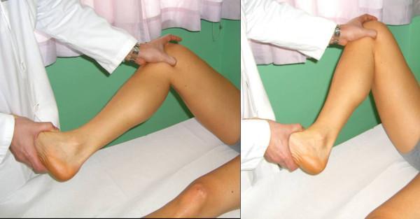
Two clinical photographs demonstrate the performance of the McMurray test, a physical examination maneuver used to evaluate for meniscal injuries of the knee. The patient is in a supine position on an examination table. In the left panel, the examiner flexes the patient's knee to approximately 90 degrees while grasping the patient's heel with one hand to control tibial rotation. The other hand is placed over the knee joint, with fingers palpating the joint line. The right panel illustrates the progression of the test, where the knee is held in a slightly more acute degree of flexion as the examiner prepares to extend the knee while applying rotational stress (internal or external rotation) and a valgus or varus force. This maneuver aims to elicit a palpable or audible 'click' or localized joint line pain, which would indicate a tear in the medial or lateral meniscus. The images highlight the correct hand placement for stabilizing the joint and manipulating the distal limb during orthopedic assessment.
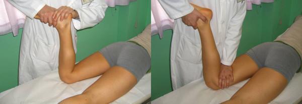
Two side-by-side clinical photographs demonstrating the Apley grinding test, a physical examination maneuver for knee pathology. The patient is positioned prone on an examination table with the affected knee flexed to 90 degrees. The examiner, wearing a white coat, is positioned at the foot of the table. The left image illustrates the distraction component of the test: the examiner grips the patient's ankle and applies an upward pulling force combined with internal or external rotation to assess for ligamentous or capsule injury. The right image illustrates the compression (grinding) component: the examiner applies a downward longitudinal force through the tibia while rotating the foot. This maneuver compresses the menisci between the femoral condyles and tibial plateau; pain during this phase suggests a meniscal lesion. The images serve as an educational guide for orthopedic clinical assessment, highlighting the importance of comparing response to distraction versus compression forces in differentiating meniscal tears from ligamentous or chondral pathology.
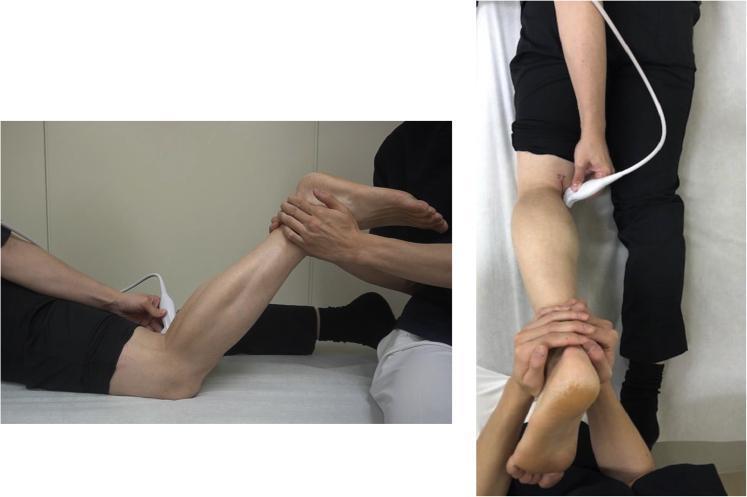
This procedural clinical photograph demonstrates the specific patient and clinician positioning for a dynamic musculoskeletal ultrasound evaluation of the posterior knee, particularly for identifying medial meniscus ramp lesions. The image consists of two views: a lateral profile and a superior posterior view. The patient is positioned prone on an examination table. The target knee is flexed to approximately 70 degrees, with an assistant manually supporting the lower leg and foot to facilitate isometric contraction during the scan. A linear ultrasound transducer is applied to the posterior aspect of the knee, specifically targeting the medial side of the popliteal fossa above the semitendinosus and semimembranosus tendons. The examiner holds the probe firmly against the skin to maintain a stable view of the deep joint structures while the patient performs resisted knee flexion. This technique is designed to visualize dynamic changes in the joint capsule and meniscus, such as the 'meniscus left behind' sign.
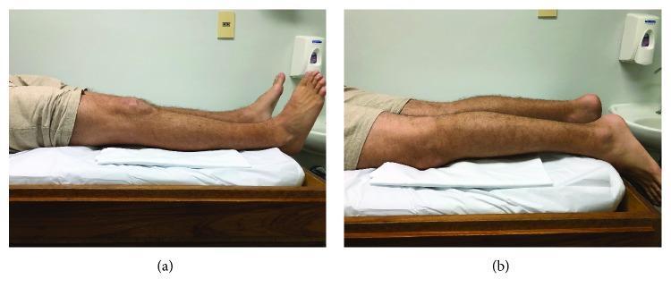
Two-panel clinical photograph demonstrating the objective measurement of knee extension deficit in a 25-year-old male. The patient is positioned prone on an examination table. Panel (a) shows the initial state following a medial meniscus bucket handle tear, where an extension lag is visible: the right knee remains flexed, causing the lower leg and foot to be elevated and dorsiflexed off the table surface compared to the contralateral side. Panel (b) illustrates the clinical outcome after a rehabilitative exercise protocol targeting arthrogenic muscle inhibition and hamstring contracture. In this image, the patient achieves full passive and active extension, with the entire length of the lower limb, including the knee, shin, and top of the foot, resting flat and parallel to the examination table surface. These images are used in orthopedics and physical therapy to document the progression of joint range of motion and the efficacy of manual or exercise-based interventions for locked knee symptoms.
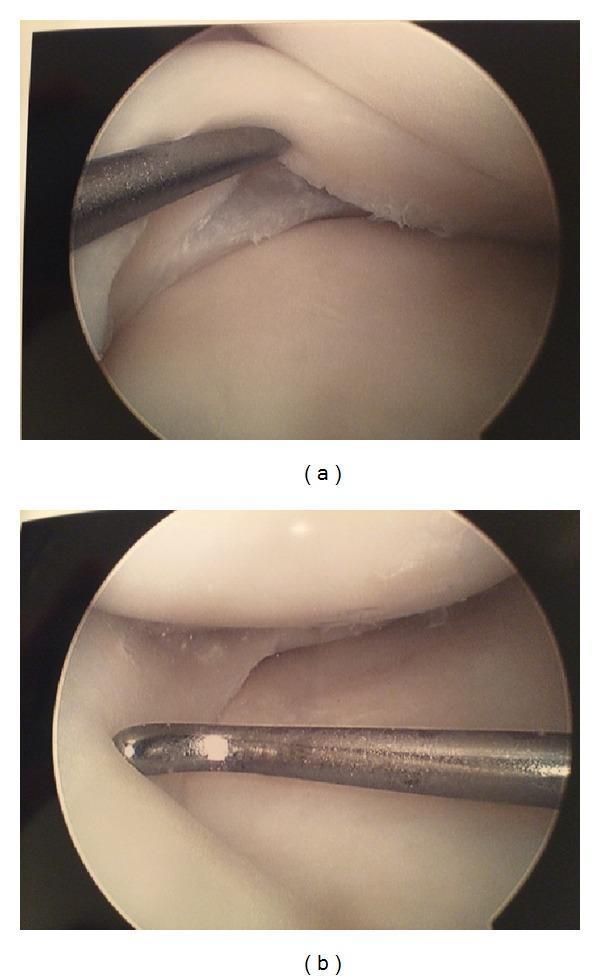
This diagnostic clinical image presents a side-by-side arthroscopic comparison of a left knee joint during a medial meniscus repair. Modality: Arthroscopy (Endoscopy). Anatomical Region: Knee joint, specifically the medial compartment. Panel (a) shows the prefixation state, demonstrating a bucket-handle type tear in the red-white zone of the medial meniscus. A metallic surgical probe is being used to manipulate the tear, revealing clean, non-frayed edges and smooth surrounding meniscal tissue. Panel (b) illustrates the postfixation state where the tear has been stabilized using an all-inside knotless suture-anchor technique. The metallic probe is again visible, confirming the integrity and reduction of the meniscal fragment against the periphery. The surrounding articular cartilage appears healthy and white. Educational significance: This image illustrates the intraoperative assessment of meniscal pathology and the visual outcome of a successful surgical repair, emphasizing the importance of probe examination to determine tissue viability and fixation stability in orthopedic sports medicine.
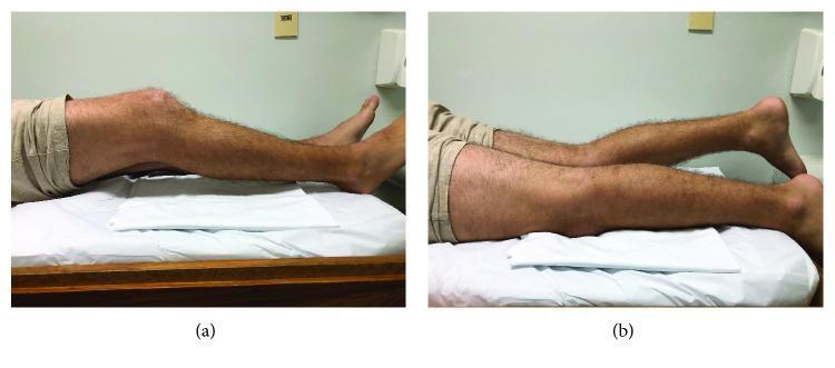
Clinical photograph in two panels (a and b) demonstrating a comparison of knee extension in a 25-year-old male patient. The patient is positioned prone on an examination table with the distal lower legs and feet hanging off the edge. A white cloth is placed under the mid-thighs for comfort and positioning. Panel (a) provides a lateral view of the right lower limb, showing a significant knee extension deficit (approximately 30 degrees of flexion) and hamstring contracture. Panel (b) offers a comparative view of both legs, highlighting the asymmetry between the affected right knee, which remains flexed, and the contralateral left knee, which exhibits full extension. This visual represents a clinical sign of arthrogenic muscle inhibition or mechanical locking following a meniscus injury (bucket handle tear). The image illustrates a key orthopedic physical examination finding used to assess range of motion and joint pathology in sports medicine and emergency orthopedics.
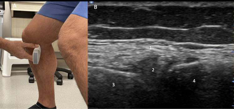
This dual-panel image demonstrates a diagnostic ultrasound examination of the medial knee joint. Panel A is a clinical photograph showing the transducer placement in a longitudinal (long-axis) orientation over the medial joint line of a standing patient with the knee flexed. Panel B is the corresponding musculoskeletal ultrasound image identifying key anatomical landmarks. The medial collateral ligament (MCL, labeled 1) is visible as a superficial, hyperechoic, fibrillar band. Deep to the MCL, the medial meniscus (labeled 2) appears as a hypoechoic, triangular, or wedge-shaped structure situated within the joint space. The underlying bony surfaces of the medial femoral condyle (labeled 3) and the proximal tibia (labeled 4) are characterized by distinct, hyperechoic cortical lines with posterior acoustic shadowing. This weighted-bearing, flexed-knee view is clinically significant for evaluating meniscal extrusion and joint space narrowing in the assessment of osteoarthritis. The educational focus is on identifying soft tissue and bony relationships in the medial compartment of the knee under functional positioning.
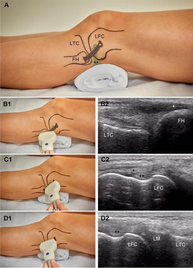
This composite educational graphic illustrates a standardized ultrasound examination protocol for assessing the lateral knee joint, specifically for measuring lateral meniscal extrusion (ME). Panel A shows a lateral clinical photograph of a knee with anatomical markings for the lateral femoral condyle (LFC), lateral tibial condyle (LTC), and fibular head (FH). Panels B1, C1, and D1 demonstrate corresponding transducer positions, while B2, C2, and D2 provide the resulting sonograms. Image B2 (Slice 1) shows the initial longitudinal plane identifying the fibular head (FH) and the lateral collateral ligament (*). Image C2 (Slice 2) shows the transducer shifted proximally to visualize the femoral attachment of the collateral ligament (*) and the popliteus tendon (**) at the LFC. Image D2 (Slice 3) displays the final measurement position at the tibiofemoral joint line, clearly depicting the relationship between the LFC, the lateral meniscus (LM), and the LTC. This standardized approach is designed to ensure consistent, reproducible measurements of meniscal displacement relative to the tibial margin in clinical and research settings.
Thessaly test meniscus grinding test knee joint line tenderness
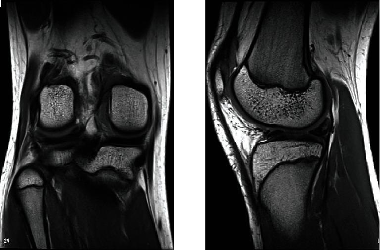
This diagnostic image displays two views (coronal and sagittal) of the knee joint via proton density-weighted Magnetic Resonance Imaging (MRI). The imaging reveals the distal femur, proximal tibia, and fibular head, alongside the patellofemoral compartment. A focal area of increased signal intensity is visible within the posterior segment of the lateral meniscus, accompanied by an apparent increase in meniscal volume and thickness compared to normal morphology. The sagittal view demonstrates the relationship between the femoral condyle and the tibial plateau, highlighting the thickened meniscus in the lateral compartment. These findings are clinically significant as they suggest structural anomalies such as a discoid lateral meniscus or a double-layered lateral meniscus, providing key diagnostic evidence for patients presenting with mechanical knee symptoms like locking or joint line tenderness.
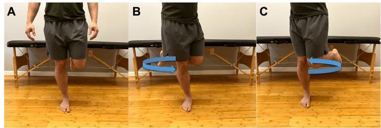
A clinical photograph series consisting of three panels (A, B, and C) demonstrating the modified Thessaly test, a physical examination maneuver used to assess for meniscal pathology. The subject is shown in a clinical setting standing barefoot on a hardwood floor. In Panel A, the individual is positioned in a single-leg stance on the affected limb with the knee in approximately 5 to 20 degrees of flexion. Panels B and C illustrate the dynamic component of the test, with blue arrows indicating internal and external rotation of the torso and femur on the fixed tibia. The maneuver is designed to apply rotational and axial loading across the knee joint. A positive result is indicated by the reproduction of joint-line pain or mechanical symptoms such as locking or catching, suggesting a possible meniscal tear. This specific sequence highlights the test's application in telehealth or orthopedic clinical assessments.
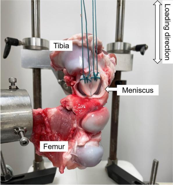
A biomechanical testing setup for an orthopedic study on knee joint meniscal repair. The clinical photograph shows a dissected knee joint specimen with the femur and tibia secured in custom-made metal jigs within a mechanical testing apparatus. The femur is oriented horizontally while the tibia is positioned vertically at the top. Between the articular surfaces of the bones, a dissected meniscus is visible, featuring green polyester sutures (No. 5 Ethibond) applied using the Krackow stitch technique at both ends of the tissue. These sutures are vertically tensioned and connected to an upper load cell jig, facilitating a tensile load-to-failure or cyclic loading test. An arrow in the top right corner indicates the vertical loading direction. The image illustrates a musculoskeletal research model used to evaluate the biomechanical stability and gap formation of various meniscal stitching techniques, such as inside-out repairs involving the peripheral meniscus and joint capsule.
Two clinical photographs demonstrate the performance of the McMurray test, a physical examination maneuver used to evaluate for meniscal injuries of the knee. The patient is in a supine position on an examination table. In the left panel, the examiner flexes the patient's knee to approximately 90 degrees while grasping the patient's heel with one hand to control tibial rotation. The other hand is placed over the knee joint, with fingers palpating the joint line. The right panel illustrates the progression of the test, where the knee is held in a slightly more acute degree of flexion as the examiner prepares to extend the knee while applying rotational stress (internal or external rotation) and a valgus or varus force. This maneuver aims to elicit a palpable or audible 'click' or localized joint line pain, which would indicate a tear in the medial or lateral meniscus. The images highlight the correct hand placement for stabilizing the joint and manipulating the distal limb during orthopedic assessment.
Clinical Tests for Meniscus Injury
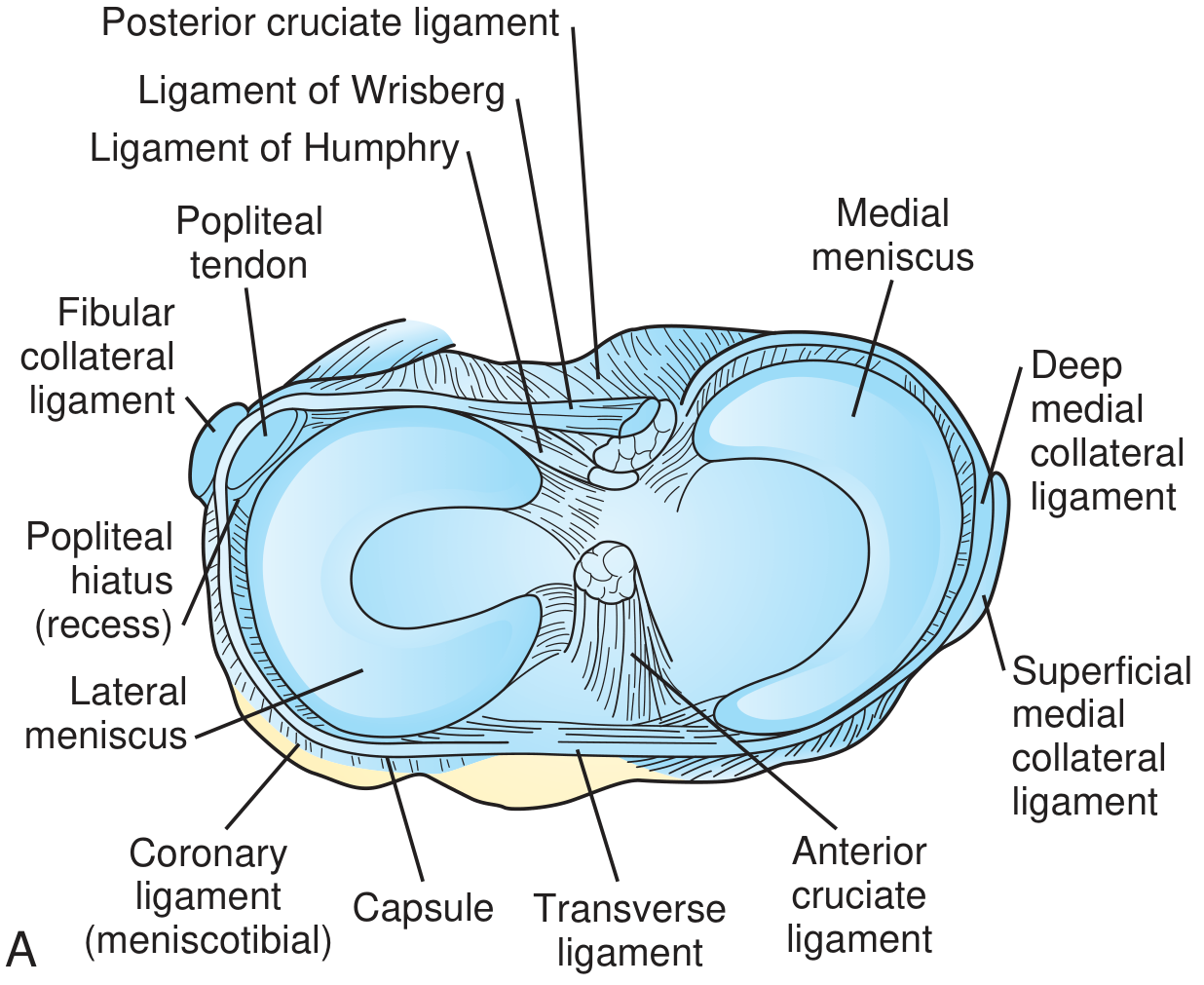
Anatomy Overview
1. Joint Line Tenderness
- Position: Knee flexed to 90°
- Technique: Palpate the medial and lateral joint lines with thumb and index finger
- Positive: Localized tenderness at the joint line
- Sensitivity: 63% | Specificity: 77%
- Note: Combined testing with McMurray and Apley improves overall accuracy
2. McMurray's Test
| Step | Action |
|---|---|
| Position | Patient supine; hip and knee fully flexed |
| Hand placement | One hand grips the ankle; other hand palpates the joint line |
| Medial meniscus | Apply valgus stress + external rotation of the tibia; slowly extend the knee |
| Lateral meniscus | Apply varus stress + internal rotation of the tibia; slowly extend the knee |
- Positive: A palpable or audible "click" or "pop" localized to the joint line, OR reproduction of pain
- A click between full flexion and 90° = posterior peripheral tear
- A click/pop at higher degrees of extension = middle or anterior meniscal tear
- The position of the knee at which the click occurs helps localize the lesion
- A negative result does not rule out a tear
3. Apley Grinding Test
| Component | Description |
|---|---|
| Position | Patient prone; knee flexed to 90° |
| Compression (Grinding) | Examiner presses down on heel (axial load) while rotating the tibia internally and externally |
| Distraction | Examiner lifts the heel while rotating - assesses ligamentous injury |
- Positive for meniscal tear: Pain with compression + rotation (menisci compressed between condyles)
- Pain with distraction suggests a ligamentous rather than meniscal lesion
- This distinction between compression pain vs. distraction pain differentiates meniscal from ligamentous injury
4. Thessaly Test
- Examiner holds patient's outstretched hands for support
- Patient stands flatfooted on the affected leg only
- Patient rotates knee and body internally and externally 3 times with knee in 5° flexion
- Repeat with knee in 20° flexion
- Always perform on the normal knee first to establish baseline and teach the patient
- Positive: Medial or lateral joint line discomfort, and/or a sense of locking or catching
5. Squat Test
- Patient performs several repetitions of a full squat
- Feet and legs alternately in full internal then full external rotation during each squat
| Rotation Producing Pain | Suggested Injury |
|---|---|
| Internal rotation | Lateral meniscus tear |
| External rotation | Medial meniscus tear |
- Note: Localization of pain to the medial or lateral joint line is a more reliable sign than the rotation position itself
Summary Table
| Test | Position | Maneuver | Positive Finding | Sensitivity | Specificity |
|---|---|---|---|---|---|
| Joint Line Tenderness | Knee 90° flexed | Palpate joint line | Localized tenderness | 63% | 77% |
| McMurray's | Supine, knee fully flexed | Valgus/varus + rotation while extending | Click/pain at joint line | 70% | 71% |
| Apley Grinding | Prone, knee 90° | Axial compression + rotation | Pain with compression | 60% | 70% |
| Thessaly | Standing on one leg | Rotation at 5° and 20° flexion | Joint line pain, locking/catching | ~94-96% | ~96% |
| Squat Test | Standing | Full squat with rotation | Medial/lateral joint line pain | Variable | Variable |
No single test reliably diagnoses a torn meniscus. Combined testing (McMurray + Apley + joint line tenderness) improves diagnostic accuracy. MRI remains the gold standard for confirmation.