
Tympanoplasty types
tympanoplasty types Wullstein classification
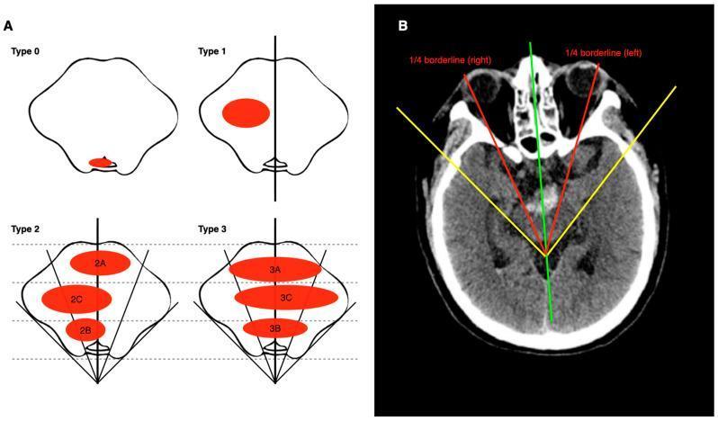
This medical illustration and diagnostic image set presents the ZJUSAH classification for Pontine Brainstem Hemorrhage (PBH). Panel A displays four schematic cross-sections of the pons outlining the classification types. Type 0 shows a hematoma restricted to the fourth ventricle or cistern. Type 1 illustrates unilateral involvement. Types 2 and 3 describe midline-spanning hematomas, further divided into subtypes (A: ventral, B: dorsal, C: central) based on their position relative to dashed lines dividing the ventral-dorsal diameter. Panel B demonstrates the application of this anatomical classification on an axial non-contrast CT head scan. It illustrates an estimation method for determining brainstem quarter-borderlines: a green line marks the ventral-dorsal midline; yellow tangent lines follow the ventrolateral edges; and red lines bisect the resulting angles to define the left and right 1/4 borderlines. This system is designed to improve prognostic accuracy and guide stereotactic surgical planning by characterizing the hematoma's spatial distribution within critical brainstem structures.
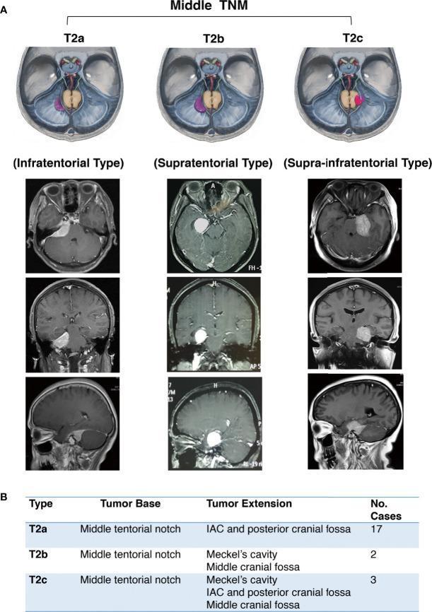
This composite educational image illustrates the classification of middle tentorial notch meningiomas (TNM) into three subtypes: T2a, T2b, and T2c. Section A provides schematic diagrams and T1-weighted axial, coronal, and sagittal MRI scans with gadolinium contrast, highlighting the growth patterns. Type T2a (Infratentorial Type) is shown with a tumor base at the middle tentorial notch extending inferiorly into the internal auditory canal (IAC) and posterior cranial fossa. Type T2b (Supratentorial Type) demonstrates a tumor mass growing superiorly from the tentorium into the middle cranial fossa, often involving Meckel’s cavity, without infratentorial extension. Type T2c (Supra-infratentorial Type) displays a bi-directional growth pattern, with the tumor mass extending both above and below the tentorium, involving the middle and posterior cranial fossae as well as the midline structures. Section B includes a summary table detailing the tumor base at the middle tentorial notch for all types and listing their respective primary extension sites and case frequencies. This resource serves for preoperative surgical planning and neurosurgical classification.
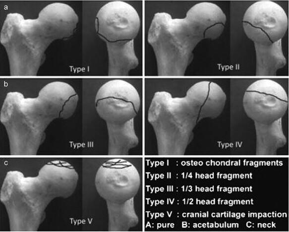
This orthopaedic anatomical diagram illustrates the Chiron classification (2004) for femoral head fractures, shown across five categorized types (Type I to Type V). Each type is presented using a dry bone model of the proximal femur from two perspectives: a lateral/oblique view and a frontal view of the femoral head. Fracture lines are demarcated by solid black lines to indicate the morphology and size of the fracture fragments. Type I displays small osteochondral fragments at the superior-lateral aspect. Type II shows a 1/4 head fragment on the anterior-superior surface. Type III demonstrates a 1/3 head fragment extending from superior to posterior. Type IV depicts a vertical fracture dividing approximately 1/2 of the femoral head. Type V illustrates cranial cartilage impaction with multiple intersecting lines across the superior articular surface. The classification is clinically relevant for orthopedic surgeons and residents for determining the severity of femoral head trauma and informing surgical decisions, such as fragment fixation versus excision based on size and location.
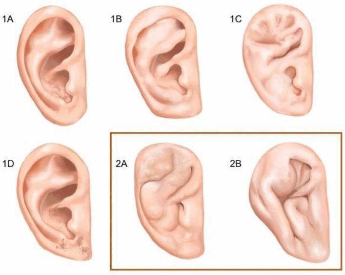
This medical illustration presents the Yotsuyanagi classification system for cauliflower ear (auricular hematoma/deformity of the pinna), categorized into two primary types based on the preservation of the auricular outline. Type 1 deformities maintain a relatively normal external ear outline and are subdivided into four categories: 1A (localized deformity within the concha), 1B (involvement extending from the antihelix to the helix), 1C (generalized deformity affecting the entire internal ear architecture), and 1D (deformity associated with skin defects or scarring). Type 2 deformities, highlighted in the orange box, represent more severe stages where the overall auricular outline is significantly altered. Type 2A displays moderate structural integrity where a distorted but recognizable ear shape remains. Type 2B shows poor structural integrity with severe distortion and loss of the characteristic anatomical outline. This diagram is an educational resource for plastic surgery and sports medicine to grade the severity of chronic auricular trauma commonly seen in contact sports like judo or wrestling.
Tympanoplasty Types (Wullstein Classification)
Wullstein Classification - All 5 Types
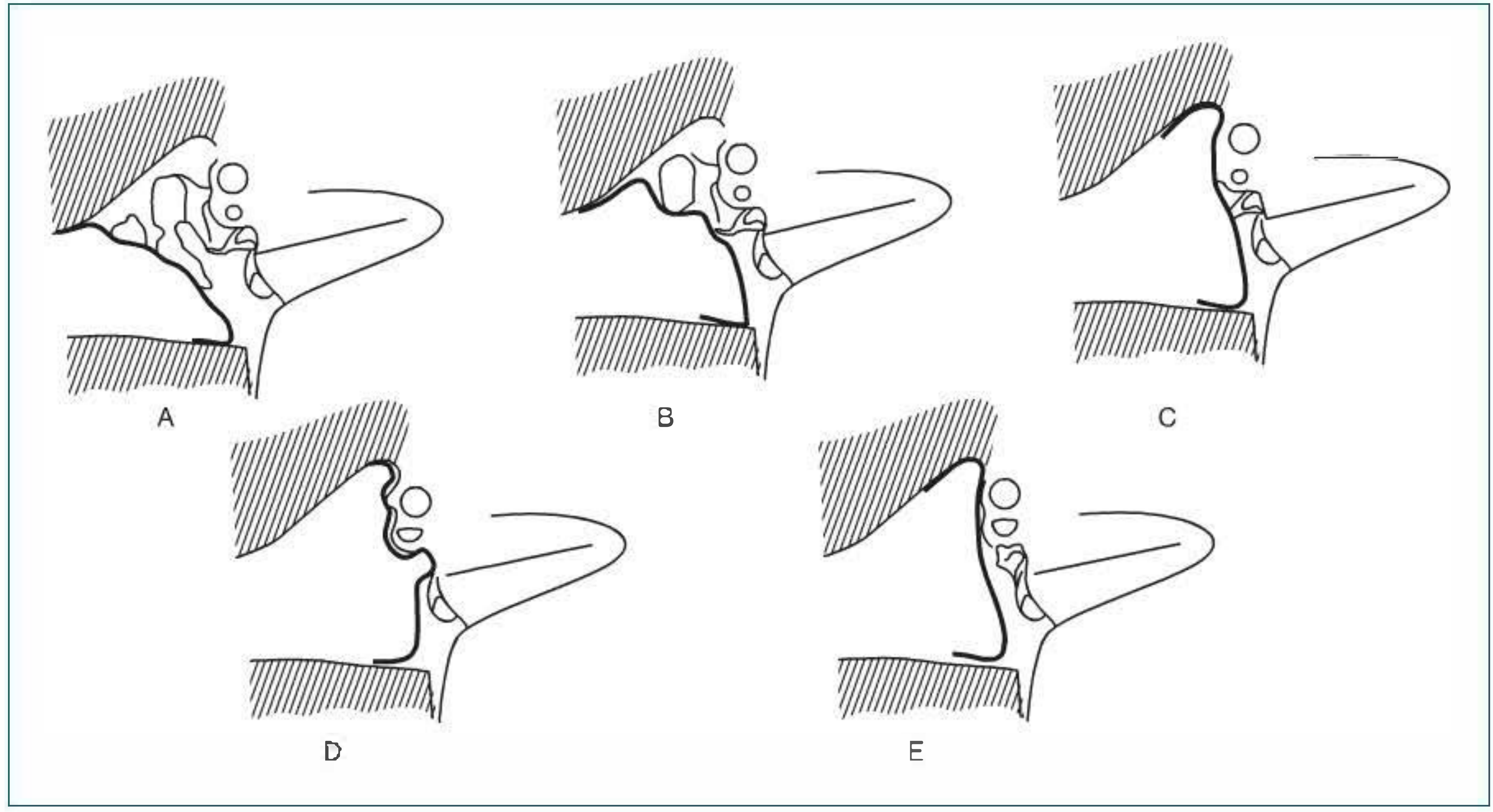
Type I - Myringoplasty
- Ossicular status: All ossicles intact and mobile
- Procedure: Repair of tympanic membrane (TM) perforation only; normal middle ear anatomy is restored
- Sound transmission: TM → malleus → incus → stapes → oval window (normal)
- Note: When limited solely to the drumhead, it is also called myringoplasty; "tympanoplasty" implies middle ear exploration in addition to grafting
Type II
- Ossicular status: Malleus handle partially or totally eroded/absent, but incus and stapes intact
- Procedure: TM graft is draped onto the remaining malleus and long process of incus; ossicular continuity is restored with the bridge remnant removed
- Modern use: Infrequently performed today; largely superseded by ossicular prostheses
Type III - Myringostapediopexy / Stapes Columella
- Ossicular status: Malleus and incus absent; stapes superstructure (capitulum) present and mobile
- Procedure: TM graft is placed directly onto the stapes head (myringostapediopexy), creating a shallow middle ear with a "columella effect"
- Sound transmission: TM → stapes head → footplate (short-circuited ossicular chain)
- Modern variants:
- Minor columella (PORP): Bone or partial ossicular replacement prosthesis interposed between stapes capitulum and undersurface of TM
- Major columella (TORP): Total ossicular replacement prosthesis from stapes footplate to TM
- Hearing results: Post-op air-bone gap ranges 10-60 dB; when stapes is mobile and middle ear aerated, average ABG is 20-25 dB. Adding a thin cartilage disk between graft and stapes head improves low-frequency hearing by 5-10 dB
- Context: Typically performed with canal-wall-down (CWD) mastoidectomy
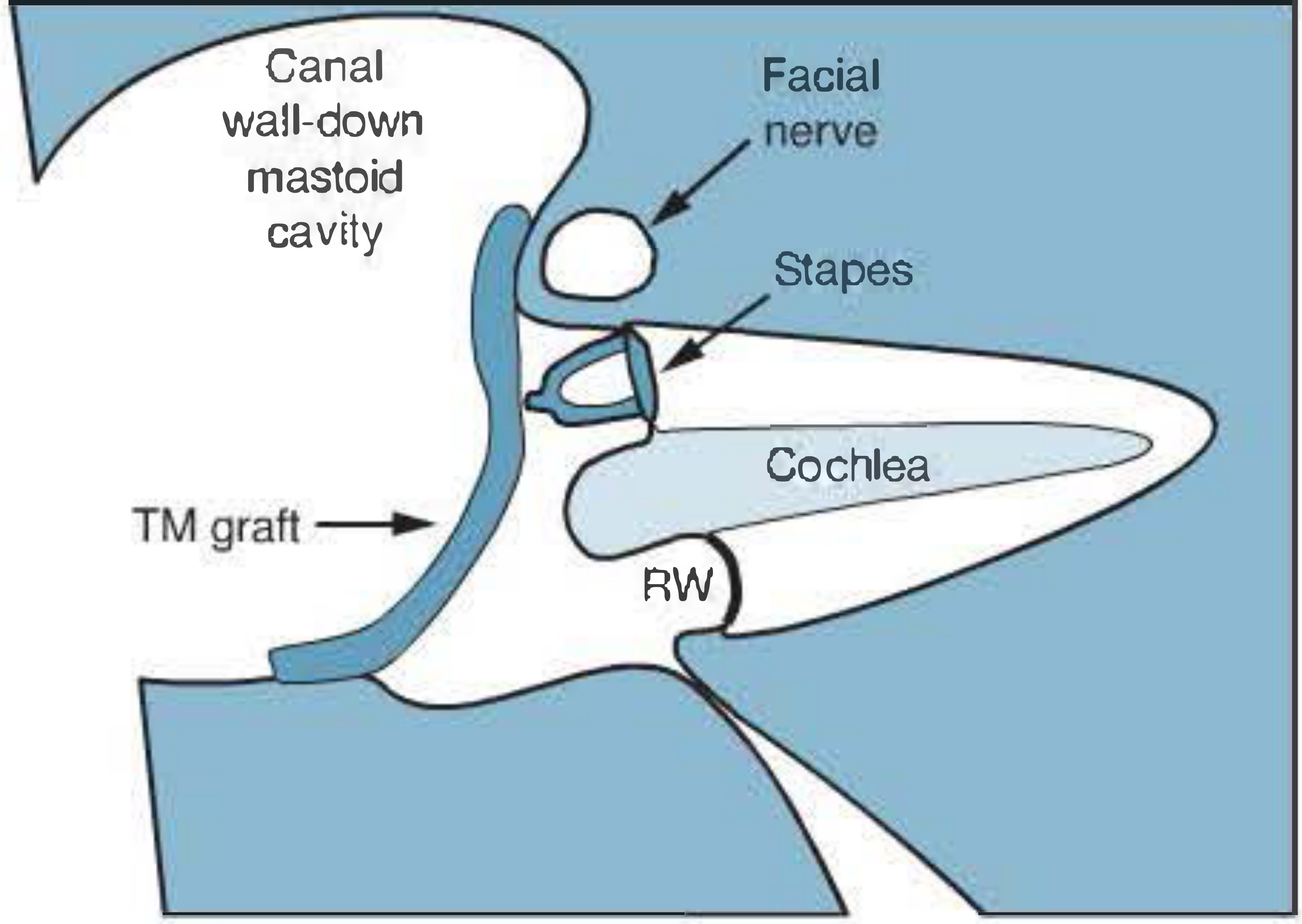
Type IV - Small Middle Ear / Round Window Protection
- Ossicular status: Stapes superstructure absent; only mobile footplate remains
- Procedure: TM graft is placed directly onto (or around) the stapes footplate, leaving the footplate exposed. The round window niche is covered to create a small, air-containing protective space
- Sound transmission: TM acts directly on the mobile footplate; round window is shielded to prevent phase cancellation (acoustic coupling)
- Hearing results: Limited; depends critically on round window protection and middle ear aeration
Type V - Fenestration / Open Oval Window
- Historical context: Designed for cases where the footplate is fixed (e.g., otosclerosis); involves creation of a fenestra in the horizontal (lateral) semicircular canal covered by cholesteatoma matrix or a tissue graft
- Modern parlance: Now describes placement of a TM graft over an open oval window (fenestrated oval window)
- Sound transmission: Directly to the fenestrated semicircular canal or oval window
Summary Table
| Type | Ossicular Status | Procedure | Mechanism |
|---|---|---|---|
| I | All intact | TM repair (myringoplasty) | Normal ossicular chain |
| II | Malleus absent/eroded; incus + stapes intact | Graft onto incus | Ossicular continuity restored |
| III | Malleus + incus absent; stapes head present | Graft on stapes head (PORP/TORP) | Columella effect |
| IV | Stapes superstructure absent; mobile footplate present | Graft on/around footplate; RW covered | Acoustic coupling, RW protection |
| V | Fixed footplate | Fenestration of semicircular canal or open oval window | New oval window via fenestra |
Additional Classification: Ossicular Defect Types (Austin/Kartush)
| Austin Type | Status | Frequency |
|---|---|---|
| A | M+, S+ | Most common (long process of incus eroded) |
| B | M+, S- | Second most common |
| C | M-, S+ | Third |
| D | M-, S- | Least common |
Surgical Approaches to Tympanoplasty
- Transcanal: For small posterior perforations in large canals; avoids mastoid dressing and postauricular incision morbidity. Fat graft myringoplasty is preferred for small persistent perforations (e.g., post-tympanostomy tube)
- Endaural: Via the ear canal and endaural incision; intermediate exposure
- Postauricular: Preferred for large perforations or when extensive middle ear work is required
Graft Techniques
- Underlay (medial): Graft placed medial to TM remnant and annulus - most common
- Overlay (lateral): Graft placed lateral to the malleus handle; used for anterior perforations
- Cartilage tympanoplasty: Perichondrium/cartilage composite grafts used in revision cases, Eustachian tube dysfunction, or cholesteatoma surgery - higher resistance to re-perforation
Macevan’s triangle
MacEwen suprameatal triangle mastoid antrum surgical landmark
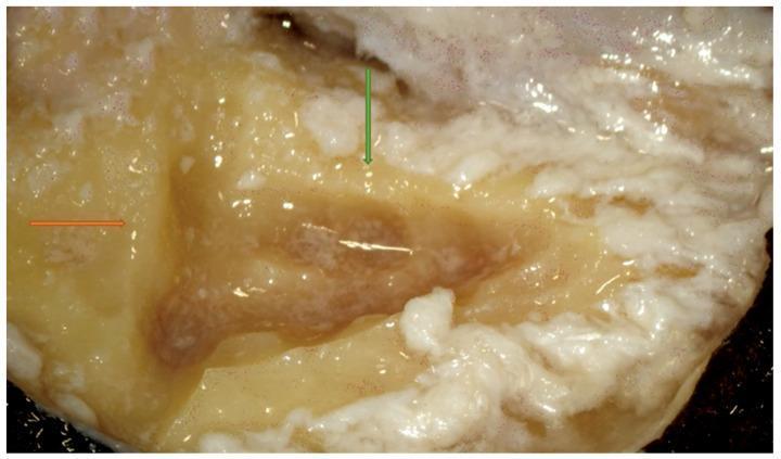
This clinical photograph displays a right-sided mastoidectomy dissection, focusing on the identification of Macewen’s suprameatal triangle. The image depicts the temporal bone cortex with initial surgical incisions. An orange arrow indicates the first straight cut made along the temporal line, which serves as the superior boundary of the attack triangle. A green arrow identifies a second cut made perpendicular to the first, positioned immediately posterior to the posterior ear canal wall. The surgical site exhibits characteristic yellowish-white bone texture with moist, reflective surfaces from irrigation. The defined triangular area serves as a critical anatomical landmark for ENT residents and surgeons to safely begin bone drilling and subsequent mastoid antrum identification. This pedagogical image illustrates the initial steps of otological surgery, emphasizing the importance of establishing accurate landmarks to avoid injury to deeper structures such as the middle cranial fossa dura or the facial nerve.
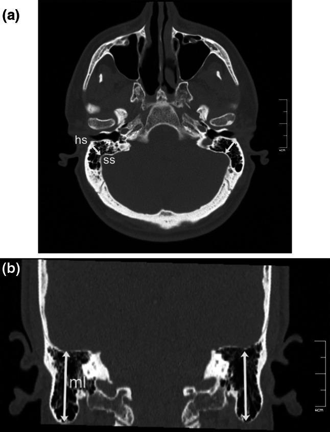
This educational resource features two reformatted computed tomography (CT) images of the human skull base and temporal bone region, highlighting key landmarks for mastoid morphometry. Image (a) is an oblique axial CT scan demonstrating 'mastoid depth.' It identifies the Henle suprameatal spine (hs) as a bony landmark on the lateral mastoid surface and illustrates the shortest distance (white arrow) to the sigmoid sinus (ss). This measurement is crucial for surgical planning in mastoidectomies to avoid vascular injury. Image (b) is a coronal reformatted CT scan showing 'mastoid length' (ml). A vertical double-headed white arrow measures the distance between the superior boundary, the tegmen tympani (the roof of the middle ear and mastoid antrum), and the inferior boundary, the mastoid tip. These diagnostic images serve as a teaching tool for radiological anatomy, specifically focusing on the spatial relationships between surgical landmarks and critical neurovascular structures within the mastoid process of the temporal bone.
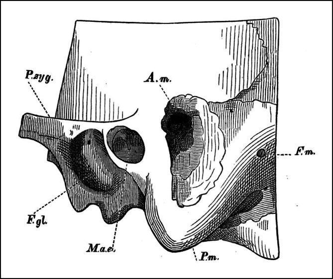
This historical anatomical diagram illustrates a lateral view of the temporal bone, specifically demonstrating a mastoidectomy procedure. The diagram depicts the mastoid process (P.m.) after a surgical opening has been created to expose the mastoid antrum (A.m.). Key landmarks include the external auditory meatus (M.a.e.) located inferior to the antrum, the zygomatic process (P.zyg.) extending anteriorly, and the glenoid fossa (F.g.l.) which accommodates the mandibular condyle. Posterior to the surgical site, the foramen of the mastoid vein (F.m.) is visible. The illustration highlights the orientation of the surgical access point, situated superior to the ear canal and inferior to the temporal line, which serves as a traditional landmark for accessing the middle ear air cell system. This technical drawing is pedagogically significant for understanding the early development of otologic surgical techniques and the spatial relationships within the mastoid portion of the temporal bone.
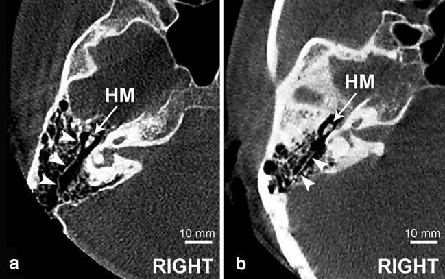
Diagnostic axial Cone Beam Computed Tomography (CBCT) scans of the right temporal bone, focused on the mastoid region at the anatomical level of the head of the malleus (HM). The images illustrate the morphology of Körner's septum (KS), a persistent petrosquamosal suture that acts as a surgical landmark within the mastoid antrum. Image (a) demonstrates a 'complete' Körner's septum, characterized by a continuous, well-defined bony lamina (indicated by white arrowheads) that extends posterior to the head of the malleus, effectively compartmentalizing the mastoid air cells into superficial (squamous) and deep (petrous) portions. Image (b) shows an 'incomplete' Körner's septum, where the bony lamina is fragmented or less extensive, lacking full division of the mastoid cellularity. These radiological findings are clinically significant for otologic surgeons, particularly during mastoidectomy, as the presence of a complete septum can mimic the medial wall of the antrum and potentially obscure deeper anatomical structures like the lateral semicircular canal or the facial nerve.
MacEwen's Triangle (Suprameatal Triangle)
Definition
Boundaries
| Boundary | Structure |
|---|---|
| Anterior | Posterior wall of the external auditory canal (EAC) |
| Superior | Supramastoid crest (temporal line / suprameatal crest) |
| Posterior | A line tangent to the posterior wall of the EAC (postero-inferior boundary) |
| Apex (anteromedial point) | Spine of Henle (suprameatal spine) - the bony prominence at the meatus that bounds this triangle |
Clinical Significance
1. Landmark for the Mastoid Antrum
2. Starting Point for Cortical Mastoidectomy
3. Spine of Henle
4. Overlying structure
Related Surgical Landmarks in the Mastoid
| Triangle/Structure | Boundaries | Significance |
|---|---|---|
| MacEwen's (suprameatal) triangle | Post. EAC wall, supramastoid crest, suprameatal spine | Surface entry to mastoid antrum |
| Trautmann's triangle | Bony labyrinth, sigmoid sinus, superior petrosal sinus/dura | Access to posterior cranial fossa |
| Citelli's (sinodural) angle | Sigmoid sinus + middle fossa dura | Risk area for sinus/dural injury |
| Solid angle | Three semicircular canals | Deepest safe limit of mastoid dissection |
| Scutum | Thin lateral wall of epitympanum (squamosa) | Eroded early in attic cholesteatoma |
Surgical Photo - Identifying MacEwen's Triangle
Important Pediatric Note
Macevan’s triangle
MacEwen's Triangle (Suprameatal Triangle)
Definition
Boundaries
| Boundary | Structure |
|---|---|
| Anterior | Posterior wall of the external auditory canal (EAC) |
| Superior | Supramastoid crest (temporal line) |
| Posterior/inferior | Tangent line to the posterior EAC wall |
| Apex | Spine of Henle (suprameatal spine) - at the anteroinferior corner |
Key Clinical Points
- Antrum lies ~1.25-1.5 cm deep to the center of this triangle in adults
- Starting point for cortical mastoidectomy - drilling begins here to access the antrum
- The tegmen mastoideum lies just medial/superior - avoid breaching it (risk of CSF leak / intracranial entry)
- The spine of Henle at its apex is a reliable palpable intraoperative landmark
- Used alongside the temporal line and postauricular region for orienting mastoid surgery
Related Landmarks
| Structure | Boundaries | Significance |
|---|---|---|
| MacEwen's triangle | Post. EAC wall, supramastoid crest, suprameatal spine | Surface entry to mastoid antrum |
| Trautmann's triangle | Bony labyrinth, sigmoid sinus, superior petrosal sinus | Posterior cranial fossa access |
| Citelli's angle | Sigmoid sinus + middle fossa dura | Risk area - sinus/dural injury |
| Solid angle | Three semicircular canals | Deepest safe limit of mastoid dissection |
| Scutum | Thin lateral wall of epitympanum | Eroded early in attic cholesteatoma |
Surgical Photo
Rabies vaccine guidelines on vaccinated pet dogs
rabies post exposure prophylaxis vaccinated dog WHO guidelines 2024
Rabies Guidelines: Bites from Vaccinated Pet Dogs
The Core Principle
Step 1: Immediate Wound Care (ALWAYS - regardless of vaccination status)
- Thorough wound washing with soap and water for at least 15 minutes
- Irrigation with a virucidal agent (povidone-iodine solution) if available
- Do NOT suture the wound primarily - leave open or use delayed closure
- Assess for tetanus prophylaxis and antibiotics as needed
Step 2: Assess the Dog's Vaccination Status
| Vaccination Status | Definition | Next Step |
|---|---|---|
| Fully vaccinated | ≥2 prior rabies vaccines, current booster | Observe 10 days - do NOT start PEP yet |
| Partially/incompletely vaccinated | Only 1 dose, or overdue booster | Treat with caution - consult public health |
| Unknown vaccination history | No records | Treat as potentially unvaccinated |
| Unvaccinated | No prior rabies vaccine | Start PEP immediately |
Step 3: The 10-Day Observation Rule (Dogs, Cats, Ferrets)
"Dogs, cats, and ferrets that are healthy and available for 10 days of observation: Persons should NOT begin vaccination unless the animal develops clinical signs of rabies."
- The dog is placed under veterinary/owner observation for 10 days
- If the dog remains healthy throughout the 10-day period → No PEP needed for the bitten person
- If the dog develops signs of rabies or dies during observation → Immediately start full PEP for the person AND submit the animal's brain for testing
Step 4: PEP Regimens (If Required)
For Previously UNVACCINATED persons (if PEP becomes necessary):
| Component | Regimen |
|---|---|
| Wound care | Immediate soap + water + povidone-iodine |
| HRIG (Human Rabies Immune Globulin) | 20 IU/kg body weight on Day 0 - infiltrate into and around wound; remainder IM at distant site |
| Rabies vaccine | 4 doses IM (deltoid only, NOT gluteal): Days 0, 3, 7, 14 |
| Immunocompromised persons | 5-dose series: Days 0, 3, 7, 14, 28 + check serology |
For Previously VACCINATED persons (prior PrEP or prior PEP):
| Component | Regimen |
|---|---|
| Wound care | Same thorough cleansing |
| HRIG | NOT given |
| Rabies vaccine | 2 doses only: Days 0 and 3 (deltoid IM) |
Important: Vaccine is never given in the gluteal area - only the deltoid (adults) or anterolateral thigh (young children). Gluteal injection has been associated with vaccine failures.
Risk Stratification by Bite Characteristics
| Bite Type | Risk Without PEP (if animal truly rabid) |
|---|---|
| Multiple severe bites, face/head | 80-100% |
| Single bite | 15-40% |
| Superficial bite on extremity | ~5% |
| Contamination of open wound by saliva | ~0.1% |
| Saliva contact on wound >24 hours old | ~0% |
Special Situations
Stray or Unwanted Dogs (even if "vaccinated"):
- May be euthanized immediately and the head submitted for rabies testing (direct fluorescent antibody test on brain tissue)
- Local health department must be notified
High-Risk Bite Sites (face, neck, hands):
- Even from a vaccinated dog - consider initiating PEP on Day 1 and stopping if the dog remains healthy at Day 10 (risk-benefit judgment, especially in rabies-endemic regions)
Rabies-Endemic vs. Rabies-Free Regions:
- In rabies-free countries (UK, Australia, Japan, much of Western Europe): risk is near zero even from unvaccinated dogs - observation may suffice
- In high-endemicity countries (India, Southeast Asia, sub-Saharan Africa): lower threshold for starting PEP, even from vaccinated animals, due to potential lapses in vaccine cold chain and documentation reliability
WHO Classification (for endemic regions):
| Category | Exposure | Action |
|---|---|---|
| I | Touch/feed animal, licks on intact skin | No PEP |
| II | Nibbling, minor scratches, abrasions without bleeding | Wound care + vaccine |
| III | Transdermal bites, scratches with bleeding, mucosal exposure | Wound care + HRIG + vaccine |
Key Points to Remember
- No PEP vaccine failures have been reported in the US since 1980 when properly administered
- HRIG must be given within 7 days of the first vaccine dose - after day 7, it is no longer recommended
- Efficacy of timely, correctly administered PEP is nearly 100%
- The antibody response takes 7-10 days to develop - this is why HRIG provides immediate passive protection
- Vaccine should never be given intragluteally (associated with failures outside the US)

Interpret this ecg of 69 years old male patient
ECG Interpretation - 69-Year-Old Male
Extracted Measurements
| Parameter | Value | Normal |
|---|---|---|
| Heart Rate | 67 bpm | 60-100 bpm ✓ |
| P Duration | 118 ms | <120 ms ✓ |
| PR Interval | 142 ms | 120-200 ms ✓ |
| QRS Duration | 88 ms | <120 ms ✓ |
| QT/QTc | 394/440 ms | QTc borderline (normal <440 ms) |
| P/QRS/T Axis | 52° / 68° / 160° | Normal frontal axis |
| RV5/SV1 | 1.185 mV / 0.584 mV | - |
| RV6/SV2 | 1.769 mV / 0.590 mV | - |
Systematic Lead-by-Lead Analysis
Rhythm
- Sinus rhythm at 67 bpm - regular, P waves present before every QRS
P Waves
- Normal duration (118 ms), normal axis (52°) - no evidence of atrial enlargement
PR Interval
- 142 ms - normal (no block, no pre-excitation)
QRS Complex
- Duration 88 ms - narrow, no bundle branch block
- Axis 68° - normal
- R wave progression: The machine flags "QRS changes V3/V4 may be due to knowing patient's gender/age" - suggesting poor R-wave progression in precordial leads V3-V4, which raises concern for anterior pathology
ST Segments & T Waves
- Machine reports: "inferior/lateral ST-T abnormality"
- T wave axis 160° - this is significantly discordant from the QRS axis (68°), indicating diffuse T wave abnormality / inversion
Machine-Generated Diagnosis (printed on ECG)
"LVH but cannot rule out anterior infarct" "Left ventricular hypertrophy" "Inferior/lateral ST-T abnormality" "Interpretation made without knowing patient's gender/age - QRS changes V3/V4 may be due to hypertrophy" "Abnormal ECG"
Clinical Interpretation
1. Left Ventricular Hypertrophy (LVH)
- RV5 = 1.769 mV and RV6 = 1.769 mV (>2.5 mV combined raises suspicion)
- Sokolow-Lyon criterion: SV1 + RV5 or RV6 - borderline in this reading
- LVH in a 69-year-old male strongly suggests longstanding hypertension or aortic valve disease as the underlying cause
2. LVH Strain Pattern vs. Ischemia
- LVH strain pattern - secondary ST depression and T wave inversion in lateral leads (I, aVL, V5-V6) and/or inferior leads, caused by the hypertrophy itself
- Lateral ischemia/infarction - ST-T changes due to coronary artery disease (LAD diagonal or circumflex territory)
- These two patterns can be impossible to differentiate on ECG alone
3. Poor R-Wave Progression (V3-V4) - Cannot Rule Out Anterior Infarct
- Poor R-wave progression or pathological Q waves in V1-V4 can indicate:
- Old anterior MI (LAD territory) - infarction with resultant Q waves or loss of R amplitude
- Anterior ischemia (ongoing or dynamic)
- May be obscured/mimicked by LVH in some cases (as the machine notes)
4. T-Wave Axis Discordance (160°)
- A T-wave axis of 160° vs. QRS axis of 68° represents a wide QRS-T angle (~92°)
- Normal QRS-T angle is <45° - this is markedly abnormal
- Indicates widespread repolarization abnormality across multiple territories
Summary Interpretation
| Finding | Assessment |
|---|---|
| Sinus rhythm, 67 bpm | Normal |
| LVH by voltage criteria | Present - likely hypertensive heart disease |
| Inferior/lateral ST-T changes | Abnormal - LVH strain vs. ischemia (cannot distinguish on ECG alone) |
| Poor R-wave progression V3-V4 | Abnormal - cannot exclude prior anterior MI |
| QTc 440 ms | Borderline prolonged |
Recommended Next Steps
- Clinical correlation - symptoms (chest pain, dyspnea, exertional angina), blood pressure history, prior ECGs for comparison
- Prior ECG comparison - if ST-T changes are new vs. chronic, this significantly changes urgency
- Troponin (if any acute symptoms) - to exclude acute ischemia
- Echocardiogram - to confirm LVH, assess wall motion abnormalities (anterior hypokinesia would support prior MI), evaluate LVEF and aortic valve
- Stress test or coronary CT angiography - if ischemia needs to be excluded
- BP measurement - if hypertension is uncontrolled, this may explain the entire picture
- Lipid panel, HbA1c, renal function - cardiovascular risk factor assessment
⚠️ Important: This ECG interpretation is for clinical reference only. The printed machine note correctly advises physician confirmation. In a symptomatic 69-year-old male, these findings warrant urgent clinical assessment to exclude active ischemia.
Troponin I blood report how much time does it take after collection
troponin I blood test turnaround time laboratory result hours
Troponin I - Time from Blood Collection to Result
Short Answer
| Setting | Time to Result |
|---|---|
| Central hospital laboratory (stat/emergency) | 45-60 minutes (in-lab) |
| Total time (collection → transport → result) | 60-120 minutes |
| Point-of-care (bedside) testing | 15-30 minutes |
| High-sensitivity Troponin I (hs-TnI) POC | 15-20 minutes |
| Outpatient/routine lab | 2-4 hours |
The quality standard benchmark for Troponin I (ED, stat, day shift) is 60 minutes in-laboratory turnaround time for 90% of samples, with a real-world example showing 58 min in-lab / 121 min total turnaround time.
The Bigger Picture: When to Draw & Repeat
| Time After Symptom Onset | Troponin I Behavior |
|---|---|
| 0-2 hours | May be normal (too early - "window period") |
| 2-6 hours | Starts rising - first detectable elevation |
| 6-12 hours | Reliably elevated if MI has occurred |
| 12-24 hours | Peaks (highest level reached) |
| 1-2 weeks | Gradually returns to normal |
Why this matters clinically:
- A normal Troponin I drawn within 2-3 hours of chest pain onset does NOT rule out MI - the result is too early
- The test must be repeated at 3 hours and again at 6 hours (serial troponin protocol) to detect a rising pattern
- A rising trend (delta troponin) is more significant than any single absolute value
- If troponin remains normal at 12 hours after symptom onset, an acute MI is effectively ruled out
Types of Troponin I Assays and Their Turnaround
| Assay Type | Example | Time | Sensitivity |
|---|---|---|---|
| Conventional cTnI | Central lab analyzer | 60-90 min | Standard |
| High-sensitivity cTnI (hs-cTnI) | Central lab | 45-60 min | Detects very low levels earlier |
| POC (point-of-care) cTnI | Bedside/ED device | 15-30 min | Slightly lower than central lab |
| Rapid POC hs-TnI | i-STAT, Cobas h232 | 8-15 min | Good sensitivity |
Practical Takeaway (for the 69-year-old patient in your ECG case)
- Draw Troponin I now (Time 0)
- Repeat at 3 hours
- Repeat again at 6 hours if still uncertain
- Result expected back from the lab within 1-2 hours of each draw
- A rising troponin + ECG changes = strong evidence of ACS requiring urgent cardiology referral