
What is coupling site in xray
coupling site X-ray radiology definition
CCD coupling layer X-ray digital detector scintillator
Coupling Site in X-ray
How It Works - The 3-Layer Chain
- Scintillator layer - X-ray photons strike a scintillator material (commonly cesium iodide, CsI) and are converted into visible light photons.
- Coupling site/layer - Visible light photons are transferred from the large-area scintillator down to the much smaller CCD chip.
- CCD chip - Light photons are converted into electrons (an electrical signal), which is then digitized into an image.
Types of Coupling
| Type | Description |
|---|---|
| Fiber optic coupling | Bundles of fine fiber optic strands funnel light from the scintillator to the CCD. Acts like a light pipe. |
| Lens coupling | An optical lens demagnifies and focuses the light from the scintillator onto the CCD chip. |
| Electron-optic coupling | Less common; uses electron optics to transfer the signal. |
Why the Coupling Site Matters
- The scintillator covers a large imaging area (e.g., a chest or abdomen), while the CCD chip is tiny (similar in size to a camera chip).
- The coupling layer must demagnify this signal without losing too much light.
- Signal loss at the coupling site is called secondary quantum sink - energy drops off because X-ray photon energies do not equal the final electron energies at the CCD. This is one of the main efficiency limitations of indirect CCD-based systems.
- Fiber optic coupling tends to be more efficient than lens coupling for light transfer, but lens systems allow greater geometric flexibility.
Context: Indirect vs. Direct Digital Radiography
- CCD-based systems are called indirect detectors because X-rays are first converted to light, then to electrons (two conversion steps).
- The coupling site is unique to indirect flat-panel or CCD detectors; it is not present in direct flat-panel detectors (amorphous selenium), where X-rays are converted directly to electrical charge without a light intermediate.
What is coupling site in usg
coupling site ultrasound USG definition acoustic coupling gel transducer
ultrasound coupling gel transducer skin acoustic interface

This figure displays two magnetic resonance imaging (MRI) views of the pelvic region, labeled (a) Treatment and (b) Registered-Referral, illustrating transducer translation restrictions for MR-guided High Intensity Focused Ultrasound (MRgHIFU). Image (a) shows an axial cross-section of the pelvis and thighs. Vertical red lines indicate 'Left Limit' and 'Right Limit,' which define the lateral boundaries for transducer movement based on the extent of acoustic coupling between the patient's skin and the gel pad. Image (b) shows a coronal view where anatomical structures including the pelvic bone and femur are labeled. Horizontal red lines denote the 'Superior limit' and 'Inferior limit,' which restrict vertical transducer translation based on the anatomical coverage of the pelvic bone and the full body outline. These boundaries are critical for treatment planning to ensure safe and effective sonication while respecting the physical range of the robotic positioner and the limits of the acoustic coupling interface.
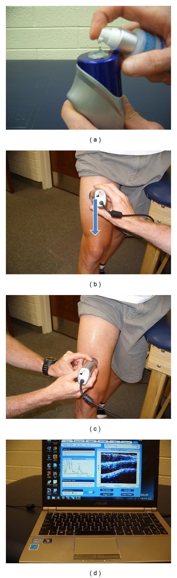
A series of four clinical photographs (a-d) demonstrating the procedural sequence for a musculoskeletal ultrasound scan of the human thigh, primarily used for body composition and tissue thickness assessment.
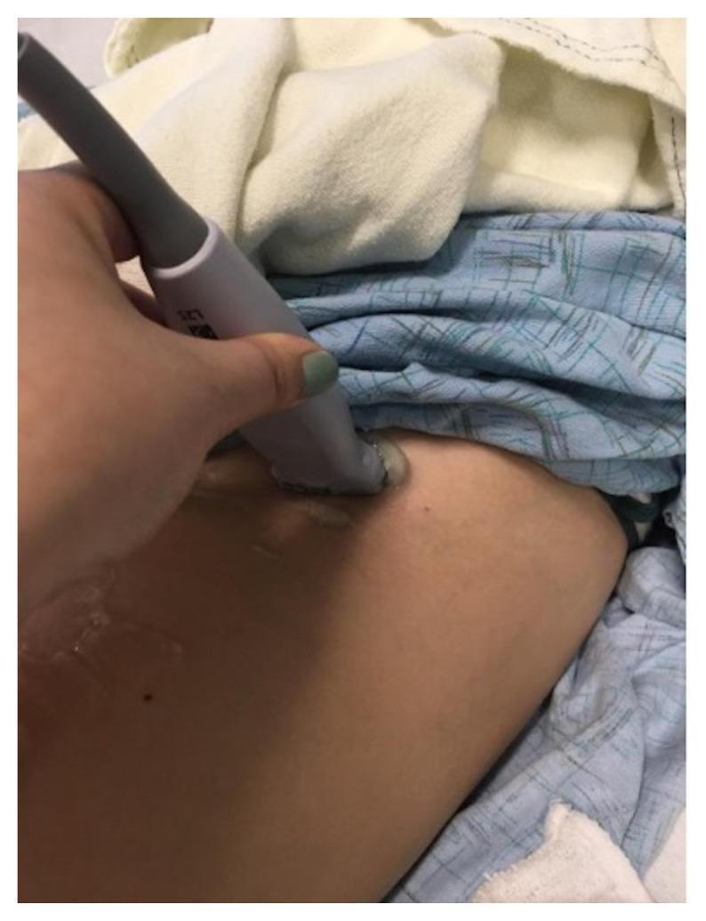
A clinical procedural photograph demonstrating the hand-eye coordination required for an ultrasound-guided femoral nerve block. The image shows a practitioner's hand holding a linear high-frequency ultrasound probe (labeled L7S) in a transverse orientation against the skin of the upper thigh/groin region. Clear acoustic coupling gel is visible at the interface between the rectangular probe head and the skin. The patient is draped with blue patterned and white linens, exposing the inguinal area for the procedure. This visual illustrates the initial positioning and transducer manipulation necessary to identify femoral anatomy, including the femoral artery, vein, and nerve, for regional anesthesia or emergency medicine residency training. The focus is on the correct grip and application of the probe to ensure optimal imaging of the femoral bundle before needle insertion.
Coupling Site in Ultrasound (USG)
Definition
Why Coupling Is Necessary
"Clinically useful ultrasound energy does not propagate through air. For this reason, a water-density substance, termed a coupling medium, is required."
The Coupling Medium (Gel)
| Setting | Coupling Agent Used |
|---|---|
| External (skin) ultrasound | Acoustic gel (sonographic jelly) |
| Transrectal/transvaginal probe | Gel between probe and condom, and between condom and mucosa |
| Intraoperative ultrasound (IOUS) | Saline on organ surface |
| Laparoscopic ultrasound (LUS) | Saline |
| Endobronchial ultrasound (EBUS) | Water-filled balloon around the probe tip |
Properties of an Ideal Coupling Medium
- Acoustic impedance close to that of soft tissue (minimizes reflection at the interface)
- Low attenuation (does not absorb or scatter sound)
- Good lubricity (allows smooth transducer movement)
- Non-irritant to skin/mucosa
- Does not damage the transducer
- Water-based, easily removed
Types of Coupling / Scanning Techniques
-
Contact scanning (direct coupling) - Transducer placed directly on the skin with gel. Most common in routine USG (abdomen, pelvis, cardiac, MSK). Can use light contact or deep compression.
-
Standoff scanning - A fluid-filled pad or water bath is placed between the transducer and tissue, so the probe does not directly touch the surface. Used when:
- The area of interest is very superficial (near-field artifacts would obscure it)
- The skin surface is irregular or painful
- Imaging neonatal scalp, superficial tendons, small parts
Poor Coupling - Consequences
- No image or severely degraded image quality
- Increased acoustic shadowing from air
- False appearance of structures due to reflection artifacts
- Inaccurate Doppler readings
Special Coupling Situations
- EBUS (Endobronchial USG): A water-filled balloon inflated around the probe tip inside the airway serves as the coupling medium between the probe and airway wall.
- Lithotripsy (ESWL): Coupling between the shockwave transducer and the patient's skin is also critical - water or gel ensures efficient energy transmission to the stone.
- Therapeutic ultrasound / Phonophoresis: Coupling gel mixed with a topical medication (e.g., hydrocortisone, ketoprofen) is used to transmit both sound waves and drug into tissue simultaneously.