
Implant removal in orthopaedics long answer
implant removal orthopaedics indications complications refracture long answer
orthopaedic implant removal plate screw refracture X-ray
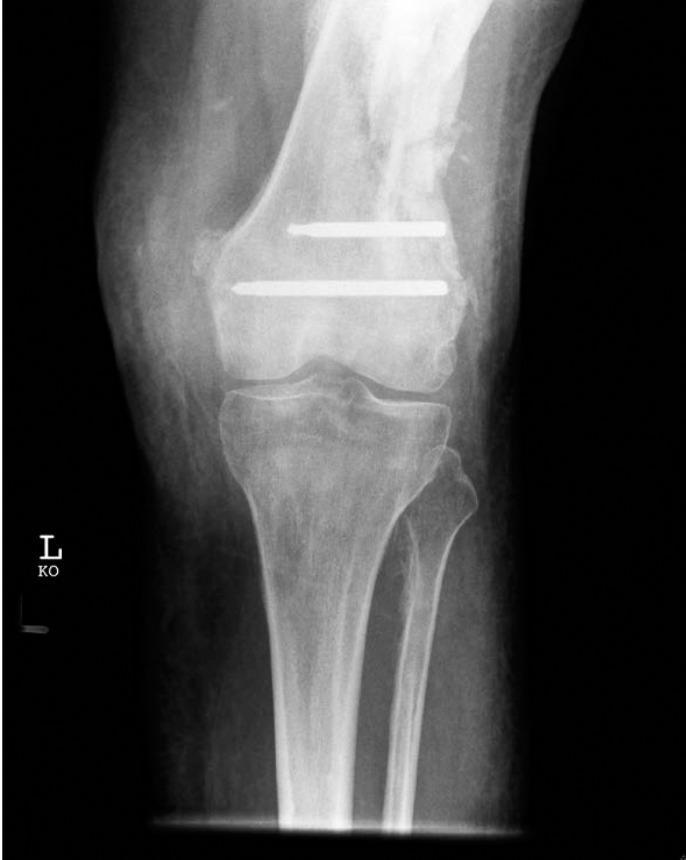
This diagnostic X-ray (radiograph) shows an anteroposterior (AP) view of a left knee joint, focusing on the distal femur, proximal tibia, and fibula. The image highlights a complication of orthopedic hardware removal. Two radiopaque, metallic locking screws are visible embedded transversely within the distal femoral metaphysis, superior to the joint line. Notably, the screw heads are absent, appearing blunt and flush with the lateral cortex of the femur. These represent retained hardware fragments after the screw heads were destroyed during a difficult extraction procedure, typically necessitated by issues such as cold welding or stripping of the Less Invasive Stabilisation System (LISS) plate. The surrounding bone shows evidence of prior surgical intervention and remodeling. This image is an educational example of orthopedic surgical complications, specifically the management of damaged locking compression plate (LCP) components during implant removal.
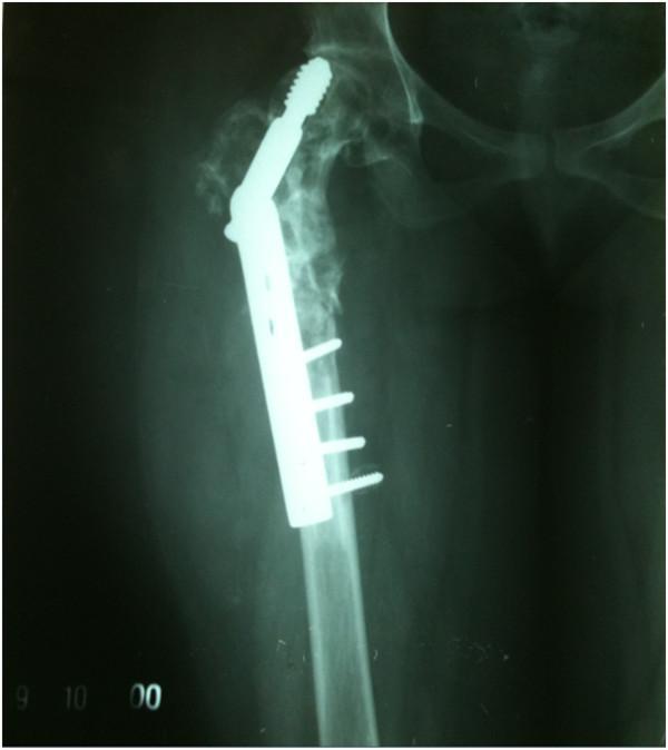
Anteroposterior (AP) X-ray of the right proximal femur and hip joint demonstrating hardware failure and significant bone pathology. A dynamic hip screw (DHS) implant is in situ, consisting of a side plate secured with four cortical screws to the femoral shaft and a large lag screw. The lag screw shows evidence of 'cut-out,' having migrated superiorly through the femoral head and penetrating into the joint space/acetabular region, indicating a failure of fracture stabilization. The proximal femur, including the neck, greater trochanter, and head, exhibits extensive, ill-defined radiolucent (lytic) lesions and a moth-eaten appearance, suggesting severe bone resorption or a pathological process such as hydatid disease. The normal trabecular pattern is lost, and the cortical thickness is irregularly reduced. This imaging illustrates implant failure secondary to poor bone quality and disease progression.
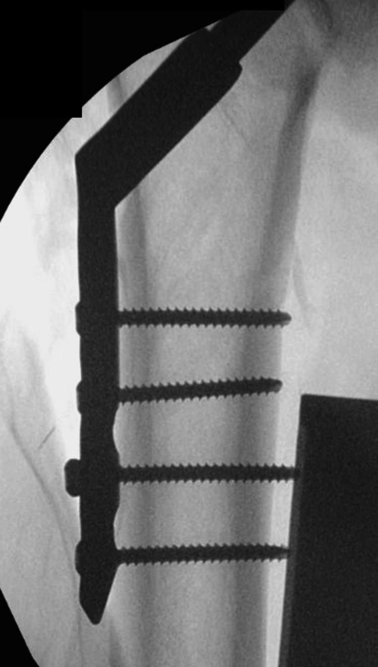
This anteroposterior (AP) x-ray radiography shows an intraoperative view of the proximal femur following internal fixation of a hip fracture. The image demonstrates a metallic Dynamic Hip Screw (DHS) system in situ. The implant consists of a long lag screw inserted through the femoral neck towards the femoral head and a lateral side plate fixed to the femoral shaft. The side plate is secured to the lateral cortex using four bicortical screws, oriented parallel to each other and perpendicular to the long axis of the plate. The bone quality exhibits increased radiolucency consistent with osteoporotic changes, and the fracture site (previously identified as intertrochanteric) is stabilized by the hardware. This visual serves as an educational example of orthopedic surgical management for AO type A1.2 intertrochanteric fractures, highlighting the correct placement and component relationship of a DHS implant for medical students and residents.
Implant Removal in Orthopaedics
Definition
Classification of Implants Removed
| Category | Examples |
|---|---|
| Internal fixation | Plates & screws (cortical, locking, cancellous), intramedullary nails, dynamic hip screws, K-wires, cerclage wires |
| External fixation | Schanz pins, ring fixator wires |
| Joint prostheses | Total knee, hip, ankle arthroplasty components |
| Syndesmotic fixation | Syndesmotic screws, suture buttons |
| Tension band | Tension band wire around patella, olecranon |
Indications for Implant Removal
1. Absolute (Mandatory) Indications
- Deep infection around metallic hardware is a major absolute indication
- Biofilm formation on implant surfaces makes eradication of infection impossible without removal
- For acute infections where bone union has NOT yet occurred, irrigation and debridement with retention may be attempted
- Once union is confirmed, the implant should be removed
- Intramedullary nails with peri-implant infection: nail removal, reaming, and placement of antibiotic-impregnated cement rods are performed to eradicate infection (Rockwood & Green's, p.2860)
- A broken intramedullary nail or plate indicates implant fatigue, usually at the non-union site, transitional zones, or interlocking screw holes
- Broken screws must be removed before re-nailing or replating
- Broken IMN removal techniques: extraction bolt / conical bolt threaded into nail; using a long hook down the cannulated portion; stacking multiple guidewires for interference fit; small cortical window approach from the far end (Rockwood & Green's, p.2860)
- Migrating K-wires from the shoulder, wrist, or hip can penetrate vital structures (lung, vessels, spinal canal)
- Must be removed urgently
- Prominent hardware causes persistent skin irritation, bursitis, or wound breakdown
- Subcutaneous hardware (e.g., ulnar plate, clavicle plate, K-wires at the elbow) is particularly symptomatic because there is minimal muscle coverage
- Ulnar plates are at highest risk because the bone is subcutaneous; plates should be placed on the dorsal or volar surface to allow some muscle coverage (Rockwood & Green's, p.415)
- Misplaced screws penetrating articular cartilage (e.g., ankle, knee, hip)
- Hardware impinging on tendons or nerves
- Implants crossing physeal plates can cause premature physeal arrest and angular deformity
- Must be removed before significant growth disturbance occurs
- A sinus tract with purulent discharge implies implant involvement - this is an absolute indication for implant removal (Firestein & Kelley's Textbook of Rheumatology)
2. Relative Indications
- Patients with recurrent deep pain at the surgical site, especially in cold weather, related to hardware presence
- Removal should only be performed after weighing risks
- Most common reason for elective removal after fracture healing
- Discomfort, restriction of movement, palpable/visible hardware
- Hardware removal before joint arthroplasty, osteotomy, or revision surgery in the same region
- Plated clavicle before shoulder arthroplasty; plated pelvis before total hip arthroplasty
- Implant removal + re-fixation with fresh bone grafting
- Broken plates at non-union site
- Syndesmotic screws in ankle fractures are often removed at 8-12 weeks to restore syndesmotic motion before weight-bearing, though suture buttons may not require removal
3. Controversial / Prophylactic Indications
- Routine removal in patients under 16 years is advocated by ~60% of surgeons (to accommodate bone growth and remodeling)
- Routine removal in adults aged 16-35 years: supported by only ~12% of surgeons
- Routine removal in patients over 35 years: only ~3% of surgeons advocate this
- Cosmetically disturbing hardware in subcutaneous locations
Timing of Implant Removal
| Implant | Minimum Waiting Time |
|---|---|
| K-wires (temporary fixation) | 3-6 weeks |
| Plates & screws (forearm, tibia) | 12-18 months minimum |
| Syndesmotic screws | 8-12 weeks |
| IMN (femur/tibia) | After confirmed union, usually 12-24 months |
| Pediatric implants crossing physis | Before growth disturbance (4-6 months) |
| Clavicular plate | 12-18 months |
- Key principle: Hardware removal from the forearm should be delayed by at least 12-18 months to allow adequate remodeling and reduce refracture risk. Protective external support (splint/brace) for 4-6 weeks post-removal is recommended (Rockwood & Green's, p.415)
- Implant removal should only be considered once fracture union is radiologically confirmed
Contraindications
- Patient medically unfit for surgery
- Implant deeply embedded with high risk of neurovascular injury on extraction
- Asymptomatic implants in elderly patients (risk-benefit unfavorable)
- Unconfirmed fracture union
- Active anticoagulation without proper bridging plan
Surgical Technique - General Principles
- Pre-operative planning: Identify the implant system and have the appropriate extraction set (matching screwdrivers, extraction bolts, conical bolts, carbide-tipped drill bits)
- Imaging: Fluoroscopy should be available intraoperatively
- Expose the implant adequately: Debride adherent soft tissue and bone overlying the implant-bone interface
- Screw extraction: Use the correct driver to engage the screw head fully; use a cannulated drill to clear bone overgrowth from screw heads; for stripped screw heads - use a trephine, screw extractor, reverse torque device, or a carbide burr to cut a new slot
- Cold welding: Titanium screws in titanium plates are prone to cold welding; use an anti-seize agent during insertion to prevent this at index surgery
- Broken screw removal: Use hollow mill drill over the screw, then reverse-torque extractor; leave if asymptomatic and deeply buried
Specific Techniques
- Standard approach over previous incision
- Remove screws before the plate
- If screws are stripped: carbide-tipped drill to remove head, or trephine around the screw and leave the shaft if not prominent
- Access the nail at the insertion site (antegrade/retrograde)
- Remove end cap, insert guidewire
- Attach extraction bolt / handle to nail
- Back-slap extractor to disengage nail
- Broken nail: conical bolt method; hook technique; cortical window method; stacking guidewires for interference fit
- Usually done in OPD or under local anesthesia
- Cut wire flush with skin if buried; use wire pulling pliers
- More complex - requires full exposure
- Debride bone-implant interface with fine chisels and osteotomes
- For total ankle arthroplasty: disengage polyethylene liner first, then remove tibial and talar components with chisels; care to avoid malleolar fracture (Campbell's Operative Orthopaedics, p.3752-3768)
Complications of Implant Removal
1. Refracture (Most Important Complication)
- Overall rate: up to 18-22% for forearm plates
- Mechanisms:
- Stress riser effect of empty screw holes: empty screw holes act as stress concentration points
- Stress shielding: the underlying cortex becomes osteoporotic under the plate due to stress shielding during the period of fixation
- Cortical defect less than 10% of bone diameter: no change in torsional strength
- Defect 10%-20% diameter: 34% drop in torsional strength
- Defects >20%: linear further decrease in strength
- Unicortical defect reduces torsional strength by 22%; bicortical defect by 26% (Rockwood & Green's, p.424-428)
- Sites: through the original fracture site OR through empty screw holes
- Early series with 4.5-mm plates reported refracture rates of 22%; later series with 3.5-mm compression plates showed lower rates
- Prevention: delay removal by 12-18 months; use a protective splint/brace for 4-6 weeks after removal; avoid torsional activities for 3-6 months
2. Infection
- Post-removal wound infection reported in up to 21% of cases
- Risk increases with deep dissection, lengthy surgical time, and poor tissue handling
3. Nerve Injury
- Particularly at risk: radial nerve (in posterior forearm), superficial peroneal nerve (lateral ankle), sural nerve (posterior ankle)
- Reported in up to 8-21% of forearm plate removals (Rockwood & Green's, p.431)
4. Vascular Injury
- Rare but serious; relevant when implants are adjacent to major vessels (e.g., pelvic fixation near iliac vessels)
5. Retained Hardware / Incomplete Removal
- Stripped screws, broken drill bits, fragment of broken nail
- Most frequent complication in large series; may be asymptomatic and left in situ if deeply buried and not causing problems
6. Hematoma / Wound Complications
- Wound dehiscence, seroma, hematoma
7. Prolonged Disability
- Hospital stay may range from 3 to 168 hours; average absence from work: 3.4 weeks (Rockwood & Green's, p.431)
8. Anesthetic Risks
- General anesthesia or regional anesthesia complications
9. Peri-implant Fracture (Intraoperative)
- Occurs especially during forceful extraction of a well-ingrown implant
- Aggressive use of osteotomes during prosthesis removal can cause malleolar fractures during ankle arthroplasty revision
Considerations by Anatomical Region
| Region | Key Considerations |
|---|---|
| Forearm (radius/ulna) | Refracture risk highest (18-22%); subcutaneous ulnar plate symptomatic; 3.5-mm plates safer than 4.5-mm |
| Tibia | Prominent proximal tibial hardware; IMN after union routinely left unless symptomatic |
| Femur | IMN: removal only if symptomatic; DHS removal after confirmed union and cessation of fracture-related pain |
| Ankle | Syndesmotic screw removal at 8-12 weeks; risk of fibula fracture if removed too early |
| Clavicle | Highly symptomatic subcutaneous plate; high refracture risk if removed before 18 months |
| Children | Routine removal; crossing-physeal implants must be removed promptly; K-wires 3-6 weeks |
Implant Removal in Special Situations
Infection-Related Removal
- For periprosthetic joint infection: one-stage or two-stage revision
- For fracture-fixation infection: removal + antibiotic cement spacer + re-fixation after infection control
- Biofilm necessitates hardware removal as antibiotics alone cannot penetrate biofilm
Broken Nail (Intramedullary)
- Most common site of nail failure: non-union site, transitional zones, interlocking holes
- Removal techniques as described above
- Filling interlocking holes with screws may reduce stress concentration
Pediatric Considerations
- ~60% of surgeons recommend routine removal in children under 16
- Implants crossing the physis: mandatory removal
- K-wires: 3-6 weeks; flexible IMN: 6-12 months after union
- Growth implications, remodeling potential, and risk of growth arrest must guide timing
Post-Operative Care After Implant Removal
- Protective splinting / bracing for 4-6 weeks (especially forearm, tibia)
- Gradual return to weight-bearing / activity
- Avoid contact sports and torsional activities for 3-6 months
- Radiological follow-up at 6 weeks to assess for refracture
- Wound care and monitoring for infection
Economic Considerations
- Implant removal carries significant economic burden: revision surgeries, prolonged hospitalization, and work absenteeism
- Particularly significant in low-income countries
- Only 7% of hospital units have a formal guideline on implant removal, highlighting variation in practice
Current Evidence & Guidelines
- The JAAOS 2022 review found a 10% overall complication rate from a pooled review of 871 patients across 10 case series; reported complications included fracture, infection, hematoma, wound dehiscence, and retained hardware
- The International Orthopaedics 2025 review notes that implant removal is "far more than a resident's simple task" - requiring thorough pre-operative planning, the appropriate extraction instruments, and experienced surgical handling
- Evidence-based literature on the expected improvement of symptoms after removal (especially in the upper extremity) remains limited and mostly retrospective
Summary
- The nature and severity of the indication (absolute vs. relative)
- The timing (adequate fracture union, minimum 12-18 months for forearm plates)
- The risks, particularly refracture, nerve injury, and infection
- The patient's age, activity level, and overall health
- Rockwood and Green's Fractures in Adults, 10th ed. 2025 - "Implant Removal and Refracture" (forearm chapter, p.415-431); "Hardware Removal and Fracture Risk" (p.424-428); "Broken Nails" (p.2860)
- Campbell's Operative Orthopaedics, 15th ed. 2026 - "Implant Removal" (total ankle revision chapter, p.3752); "Fixation and Implant Removal" (ankle syndesmosis chapter)
- International Orthopaedics 2025 - Implant removal review
- JAAOS Global 2022 - Indications and risks of implant removal
Radial shaft anterior approach
anterior Henry approach radius forearm anatomy dissection diagram
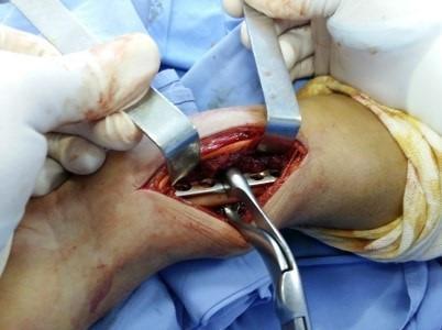
This clinical photograph captures an intraoperative view of an orthopedic surgical procedure on the forearm, specifically demonstrating the Henry anterior approach. The surgical field shows an open longitudinal incision with skin and subcutaneous tissues held back by two metal retractors (Farabeuf type), exposing the deep muscle layers and the underlying radius. Within the incision, a metallic internal fixation plate with multiple screw holes is positioned over the bone to treat a Galeazzi fracture-dislocation. A pair of surgical forceps (plate holders) is visible, stabilizing the hardware against the bone surface. The surrounding area is draped with blue sterile surgical cloths, and the operating surgeon's hands are visible in white sterile gloves. The image illustrates the principles of open reduction and internal fixation (ORIF), highlighting anatomical exposure and the use of orthopedic instrumentation for fracture stabilization.
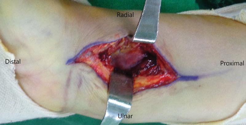
This clinical photograph demonstrates an intraoperative view of a conventional Henry approach to the distal radius. The image shows a longitudinal surgical incision on the volar aspect of the wrist, with the skin edges marked in blue. The surgical field is exposed using two metallic retractors (Senn or Army-Navy type) placed at the radial and ulnar borders of the wound. Anatomical orientation is explicitly labeled: Distal (left/hand), Proximal (right/forearm), Radial (top), and Ulnar (bottom). Deep to the skin and subcutaneous fat (yellowish tissue), the dissection exposes deeper muscular and fascial layers (reddish-pink tissue). This approach is specifically characterized by dissection between the flexor carpi radialis (FCR) tendon and the radial artery, intentionally sparing the FCR tendon sheath to minimize postoperative adhesions and maintain the integrity of the tendon's gliding mechanism. This visual is intended for orthopedic surgical education regarding volar distal radius fracture fixation.
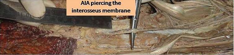
This clinical photograph displays a cadaveric dissection of the human forearm, focusing on the deep vascular anatomy. The primary subject is the anterior interosseous artery (AIA) as it perforates the interosseous membrane. The artery appears as a fine, thread-like vessel, which is being highlighted and manipulated by a pair of metallic surgical forceps. The interosseous membrane is visible as a thin, fibrous connective tissue sheet between the radius and ulna. Surrounding the vessel is a dissected tissue bed consisting of reddish-brown skeletal muscle fibers and yellowish adipose and connective tissue. A metallic retractor is positioned on the left side of the frame to maintain surgical exposure of the deep forearm compartment. This anatomical demonstration is clinically significant for understanding the vascular basis of the anterior interosseous artery perforator flap, commonly used in reconstructive hand and wrist surgery. The image serves as an educational resource for medical students and surgeons studying microsurgical anatomy and forearm flap design.

A clinical photograph of a surgical cadaveric dissection of the distal forearm and wrist region. The image utilizes a color overlay to highlight vascular anatomy. The primary focus is the radial artery, shown in bright red, along with a highlighted 'perforating branch (radial a.)' extending toward the deeper musculature. Metal surgical retractors are used to expose the deeper anatomical compartment, revealing the underlying muscles, tendons, and connective tissue. The dissection follows a modified Henry approach to expose the pronator quadratus (PQ) muscle. The photograph demonstrates the anatomical relationship between the radial artery's distal perforators and the surrounding forearm structures, serving as an educational resource for plastic and reconstructive surgery, specifically for designing pedicled muscle flaps for opponensplasty.
Anterior (Henry's) Approach to the Radial Shaft
Introduction / Overview
Indications
- Fractures of the radial shaft (ORIF)
- Galeazzi fracture-dislocation (radial shaft fracture + distal radioulnar joint disruption)
- Distal radius fractures (volar plating)
- Radial osteotomy (malunion correction)
- Tumours or biopsy of the radial shaft
- Compartment syndrome decompression (volar forearm)
- Exploration/repair of radial artery
Internervous Plane
| Structure | Nerve supply |
|---|---|
| Brachioradialis (lateral) | Radial nerve |
| Pronator teres proximally / Flexor carpi radialis distally (medial) | Median nerve |
Position
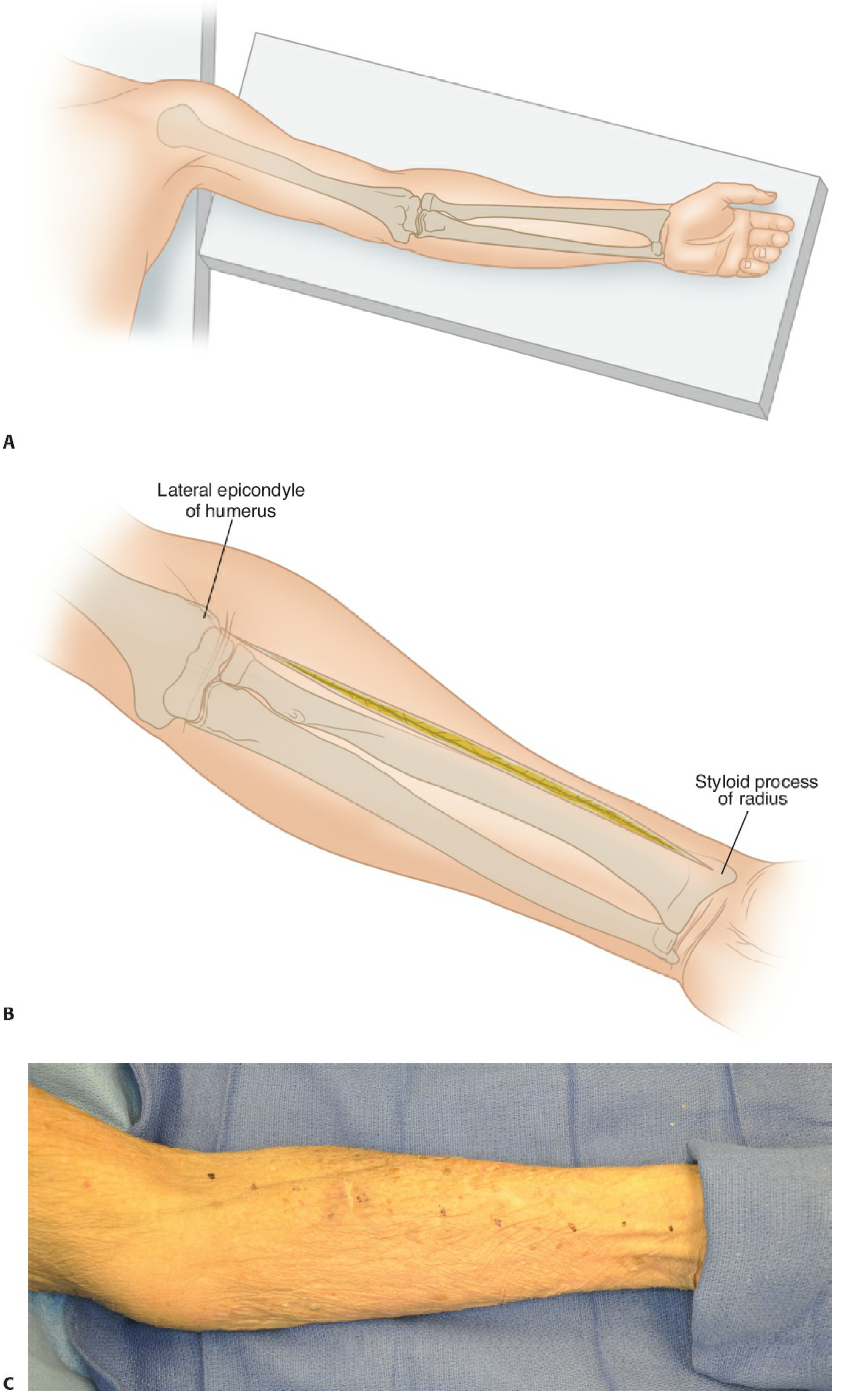
- Patient supine
- Arm abducted on a hand/arm table
- Forearm supinated (palm facing upward)
Incision
- A straight or gently curved incision is drawn along a line connecting the lateral aspect of the biceps tendon proximally to the radial styloid distally
- This places the incision along the ulnar border of the brachioradialis
- The incision can be centered over the fracture site when only partial exposure is needed
- The skin and subcutaneous fat are incised and the deep fascia is identified
Superficial Dissection
- Interval between brachioradialis (lateral) and pronator teres (medial)
- Interval between brachioradialis (lateral) and flexor carpi radialis (medial)
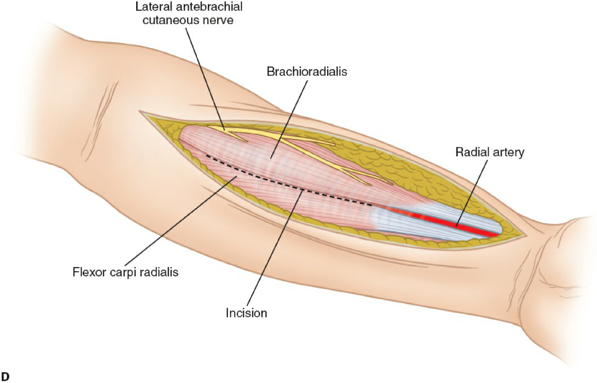
- In the proximal and middle third, the radial artery and its venae comitantes run under brachioradialis, between FCR and brachioradialis
- In the distal third, the radial artery assumes a position between FCR and brachioradialis
- To allow ulnar retraction of the radial artery with FCR: several vascular branches from the radial artery to brachioradialis must be identified and ligated or cauterized
- The superficial sensory (cutaneous) branch of the radial nerve runs on the undersurface of brachioradialis, lateral to the radial vascular bundle
- It is retracted laterally along with brachioradialis - never cut
- The terminal branch of the musculocutaneous nerve, running along the lateral forearm, should be identified and protected at the proximal end of the incision
Deep Dissection - By Level
- Pronator quadratus (PQ) - distal third
- Flexor digitorum superficialis (FDS) - middle third
- Pronator teres (PT) - middle third
- Supinator - proximal third
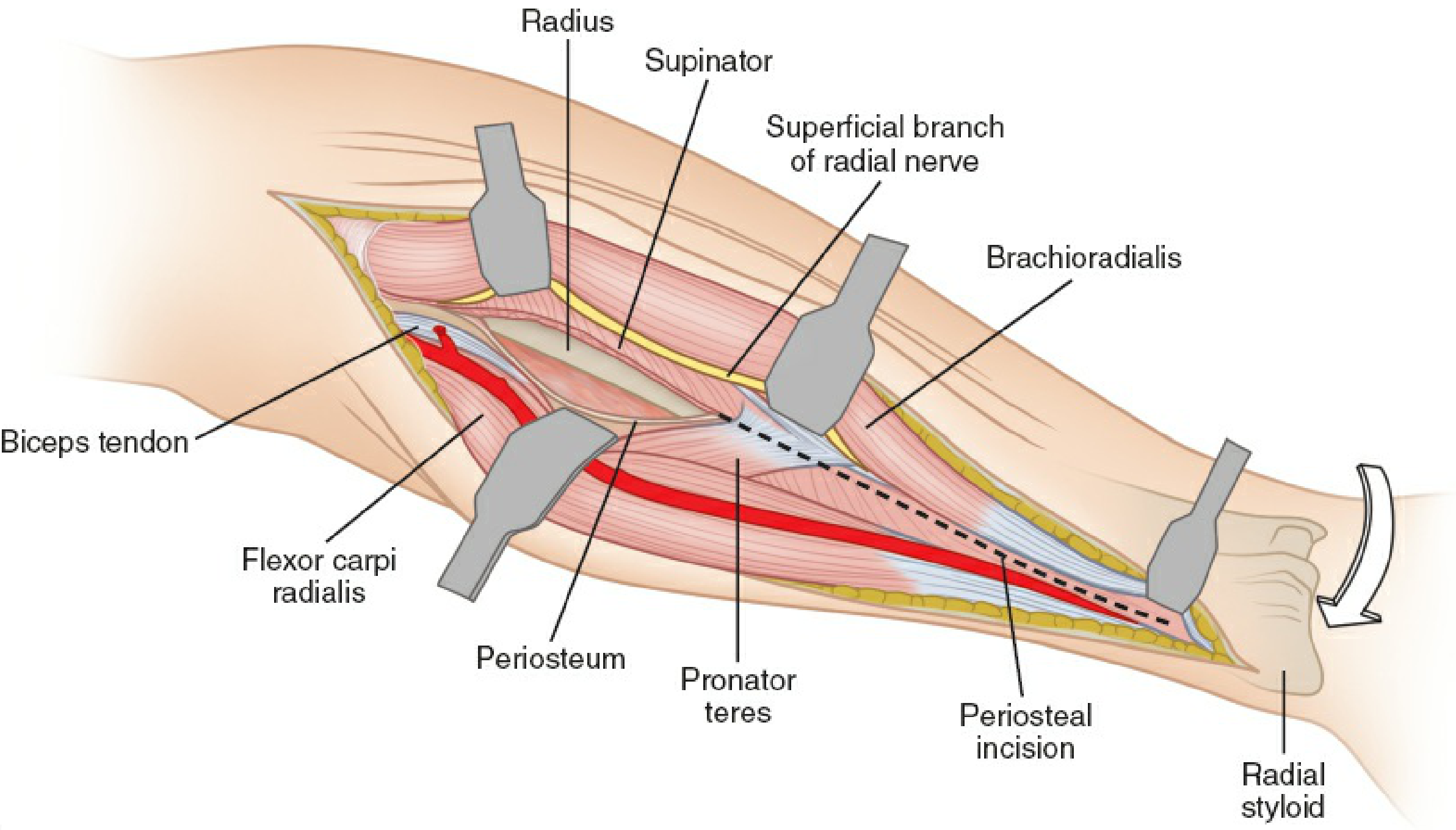
Proximal Third - Supinator
- To expose the proximal radial shaft, the supinator muscle must be released from its radial origin
- The posterior interosseous nerve (PIN) runs within the substance of supinator
- Critical step: fully supinate the forearm to rotate the PIN into a posterior and ulnar position, away from the surgical field. Retraction around the radial neck must be avoided
- The supinator is then elevated subperiosteally from its radial origin
- If access to the very proximal radius / radial head and neck is needed, the bicipital bursa is incised lateral to the distal biceps tendon - this avoids the brachial artery and its bifurcation (located medial to the tendon)
- Leash of Henry: the radial recurrent artery (branch of radial artery) and its accompanying veins must be ligated to allow medial retraction of the proximal radial artery and access to the proximal radius
Middle Third - Pronator Teres & FDS
- Pronate the forearm to bring the pronator teres insertion into view on the lateral aspect of the radius
- The radial origins of PT and FDS (distal to the supinator) are incised subperiosteally
- Complete detachment of PT should be avoided where possible - preserve the distal ulnar attachment
Distal Third - Pronator Quadratus
- The flexor pollicis longus (FPL) is swept ulnarly to expose the underlying PQ
- Supinate the forearm to rotate the PQ into view
- PQ is released from its radial origin and reflected ulnarly
- The distal border of PQ is sharply incised along the watershed line (just proximal to the volar wrist capsule) to allow complete elevation
- The distal radius can alternatively be approached through a window medial to the radial artery through the floor of the FCR tendon sheath
Summary of Forearm Positions During Deep Dissection
| Level | Forearm Position | Reason |
|---|---|---|
| Proximal third (supinator) | Full supination | Rotates PIN posteriorly/ulnarly away from field |
| Middle third (PT, FDS) | Pronation | Brings PT/FDS insertion on lateral radius into view |
| Distal third (PQ) | Supination | Rotates PQ into the surgical field |
Intraoperative photo
Structures at Risk and How to Protect Them
| Structure | Risk | How to Protect |
|---|---|---|
| Superficial branch of radial nerve | Cut or stretch during retraction of brachioradialis | Identify early; retract laterally with brachioradialis; never retract medially |
| Posterior interosseous nerve (PIN) | Injury during proximal supinator release | Fully supinate forearm before elevating supinator; do not place retractors around radial neck |
| Radial artery | Division during medial retraction; injury proximally (near bifurcation) | Identify in distal third first; ligate radial artery branches to brachioradialis; incise bicipital bursa lateral to biceps tendon proximally |
| Lateral antebrachial cutaneous nerve | Inadvertent cut in proximal incision | Identify and protect at the lateral edge of biceps tendon |
| Pronator teres insertion | Avulsion weakens forearm pronation | Release subperiosteally; avoid complete detachment |
| Brachial artery bifurcation | Injured if bicipital bursa incised medially | Always incise lateral to the distal biceps tendon |
Advantages of the Anterior Approach
- True internervous plane (radial / median) - safe, reproducible
- Extensile - entire radius from bicipital tuberosity to radial styloid accessible
- Excellent for distal radius volar plating (FCR approach variant)
- Lower risk of tendon irritation compared to dorsal (Thompson) approach
- Radial artery is identifiable as a reliable landmark throughout
- Forearm pronation/supination can be used to improve access at each level
Disadvantages / Limitations
- Proximal radius (radial head, proximal neck) access is limited
- PIN at risk during proximal exposure if supination not maintained
- Radial artery must be mobilized and protected throughout
- Not ideal when combined dorsal approach is needed
Closure
- Subperiosteal muscles (supinator, PT, FDS, FPL, PQ) are reapproximated to bone using absorbable sutures through drill holes or bone anchors, or directly to periosteum
- Deep fascia and subcutaneous tissues closed in layers
- Skin closure
- Rockwood and Green's Fractures in Adults, 10th ed. 2025 - "Volar Approach of Henry," Figs. 42-25A through K (p.1787-1794)
- Miller's Review of Orthopaedics, 9th ed. - "Anterior (Henry) Approach," Surgical Approaches to the Forearm (p.171-172)
Make the implant removal answer into PDF form
ls -la /tmp/workspace/ 2>/dev/null || echo "workspace does not exist yet"
mkdir -p /tmp/workspace/implant-removal-pdf
~/implant-removal-pdf/generate_pdf.py
from reportlab.platypus import (
SimpleDocTemplate, Paragraph, Spacer, Table, TableStyle,
HRFlowable, KeepTogether, PageBreak
)
from reportlab.lib.styles import getSampleStyleSheet, ParagraphStyle
from reportlab.lib import colors
from reportlab.lib.pagesizes import A4
from reportlab.lib.units import cm, mm
from reportlab.lib.enums import TA_CENTER, TA_LEFT, TA_JUSTIFY
OUTPUT = "/tmp/workspace/implant-removal-pdf/Implant_Removal_Orthopaedics.pdf"
# ── Page geometry ──────────────────────────────────────────────────────────────
doc = SimpleDocTemplate(
OUTPUT,
pagesize=A4,
leftMargin=2.2*cm, rightMargin=2.2*cm,
topMargin=2.2*cm, bottomMargin=2.2*cm,
title="Implant Removal in Orthopaedics",
author="Orris Medical"
)
W, H = A4
# ── Colour palette ─────────────────────────────────────────────────────────────
C_DARK = colors.HexColor("#1a2e4a") # dark navy
C_MID = colors.HexColor("#2d6a9f") # medium blue
C_LIGHT = colors.HexColor("#dce8f5") # pale blue
C_ACCENT = colors.HexColor("#c0392b") # red accent
C_GREEN = colors.HexColor("#1e6b45") # dark green
C_LGREY = colors.HexColor("#f4f4f4") # light grey for alt rows
C_WHITE = colors.white
C_BLACK = colors.HexColor("#1a1a1a")
# ── Styles ─────────────────────────────────────────────────────────────────────
base = getSampleStyleSheet()
def ps(name, parent="Normal", **kw):
return ParagraphStyle(name, parent=base[parent], **kw)
styles = {
"title": ps("DocTitle", "Title",
fontSize=22, textColor=C_DARK, spaceAfter=4,
fontName="Helvetica-Bold", alignment=TA_CENTER),
"subtitle": ps("DocSub", fontSize=12, textColor=C_MID,
spaceAfter=2, alignment=TA_CENTER, fontName="Helvetica"),
"date": ps("DocDate", fontSize=9, textColor=colors.grey,
spaceAfter=16, alignment=TA_CENTER, fontName="Helvetica-Oblique"),
"h1": ps("H1", fontSize=13, textColor=C_WHITE,
fontName="Helvetica-Bold", spaceBefore=14, spaceAfter=6,
leftIndent=-4, leading=18),
"h2": ps("H2", fontSize=11, textColor=C_DARK,
fontName="Helvetica-Bold", spaceBefore=10, spaceAfter=4,
borderPad=2),
"h3": ps("H3", fontSize=10, textColor=C_MID,
fontName="Helvetica-Bold", spaceBefore=7, spaceAfter=3),
"body": ps("Body", fontSize=9.5, leading=14, spaceAfter=5,
textColor=C_BLACK, alignment=TA_JUSTIFY),
"bullet": ps("Bullet", fontSize=9.5, leading=13, spaceAfter=3,
textColor=C_BLACK, leftIndent=14, firstLineIndent=-10),
"subbullet": ps("SubBullet", fontSize=9, leading=12, spaceAfter=2,
textColor=C_BLACK, leftIndent=26, firstLineIndent=-10),
"caption": ps("Caption", fontSize=8, textColor=colors.grey,
alignment=TA_CENTER, fontName="Helvetica-Oblique"),
"note": ps("Note", fontSize=8.5, textColor=C_GREEN,
fontName="Helvetica-Oblique", spaceAfter=4),
"source": ps("Source", fontSize=7.5, textColor=colors.grey,
fontName="Helvetica-Oblique", spaceAfter=2),
}
# ── Helper builders ────────────────────────────────────────────────────────────
def section_header(text):
"""Coloured banner for H1 sections."""
tbl = Table([[Paragraph(text, styles["h1"])]], colWidths=[W - 4.4*cm])
tbl.setStyle(TableStyle([
("BACKGROUND", (0,0), (-1,-1), C_DARK),
("TOPPADDING", (0,0), (-1,-1), 6),
("BOTTOMPADDING", (0,0), (-1,-1), 6),
("LEFTPADDING", (0,0), (-1,-1), 10),
("RIGHTPADDING", (0,0), (-1,-1), 10),
("ROUNDEDCORNERS", [4]),
]))
return tbl
def h2(text):
return Paragraph(text, styles["h2"])
def h3(text):
return Paragraph(text, styles["h3"])
def body(text):
return Paragraph(text, styles["body"])
def bullet(text, sub=False):
s = styles["subbullet"] if sub else styles["bullet"]
return Paragraph(f"• {text}", s)
def spacer(h=4):
return Spacer(1, h*mm)
def hr(color=C_MID, thickness=0.5):
return HRFlowable(width="100%", thickness=thickness, color=color, spaceAfter=4)
def two_col_table(data, col_widths=None, header=True):
"""Generic styled 2-column table."""
if col_widths is None:
col_widths = [(W-4.4*cm)*0.38, (W-4.4*cm)*0.62]
t = Table(data, colWidths=col_widths, hAlign="LEFT")
style = [
("FONTNAME", (0,0), (-1,-1), "Helvetica"),
("FONTSIZE", (0,0), (-1,-1), 9),
("LEADING", (0,0), (-1,-1), 13),
("VALIGN", (0,0), (-1,-1), "TOP"),
("TOPPADDING",(0,0), (-1,-1), 4),
("BOTTOMPADDING",(0,0),(-1,-1),4),
("LEFTPADDING",(0,0),(-1,-1),6),
("RIGHTPADDING",(0,0),(-1,-1),6),
("GRID", (0,0), (-1,-1), 0.4, colors.HexColor("#c0c0c0")),
("ROWBACKGROUNDS",(0,0),(-1,-1),[C_WHITE, C_LGREY]),
]
if header:
style += [
("BACKGROUND", (0,0), (-1,0), C_MID),
("TEXTCOLOR", (0,0), (-1,0), C_WHITE),
("FONTNAME", (0,0), (-1,0), "Helvetica-Bold"),
("FONTSIZE", (0,0), (-1,0), 9),
]
t.setStyle(TableStyle(style))
return t
def multi_col_table(data, col_widths=None, header=True):
"""Generic styled multi-column table."""
avail = W - 4.4*cm
if col_widths is None:
n = len(data[0])
col_widths = [avail/n]*n
t = Table(data, colWidths=col_widths, hAlign="LEFT", repeatRows=1)
style = [
("FONTNAME", (0,0), (-1,-1), "Helvetica"),
("FONTSIZE", (0,0), (-1,-1), 8.5),
("LEADING", (0,0), (-1,-1), 12),
("VALIGN", (0,0), (-1,-1), "TOP"),
("TOPPADDING",(0,0), (-1,-1), 4),
("BOTTOMPADDING",(0,0),(-1,-1),3),
("LEFTPADDING",(0,0),(-1,-1),5),
("RIGHTPADDING",(0,0),(-1,-1),5),
("GRID", (0,0), (-1,-1), 0.4, colors.HexColor("#c0c0c0")),
("ROWBACKGROUNDS",(0,1),(-1,-1),[C_WHITE, C_LGREY]),
]
if header:
style += [
("BACKGROUND", (0,0), (-1,0), C_DARK),
("TEXTCOLOR", (0,0), (-1,0), C_WHITE),
("FONTNAME", (0,0), (-1,0), "Helvetica-Bold"),
("FONTSIZE", (0,0), (-1,0), 9),
]
t.setStyle(TableStyle(style))
return t
def box_note(text, color=C_LIGHT, border=C_MID):
"""Highlighted note box."""
t = Table([[Paragraph(text, styles["body"])]], colWidths=[W-4.4*cm])
t.setStyle(TableStyle([
("BACKGROUND", (0,0), (-1,-1), color),
("BOX", (0,0), (-1,-1), 1, border),
("TOPPADDING", (0,0), (-1,-1), 6),
("BOTTOMPADDING", (0,0), (-1,-1), 6),
("LEFTPADDING", (0,0), (-1,-1), 10),
("RIGHTPADDING", (0,0), (-1,-1), 10),
]))
return t
# ── Cover page ─────────────────────────────────────────────────────────────────
def cover_page():
elems = []
elems.append(spacer(30))
# top banner
banner = Table(
[[Paragraph("ORTHOPAEDICS", ps("BannerTop", fontSize=11,
textColor=C_LIGHT, fontName="Helvetica-Bold",
alignment=TA_CENTER))]],
colWidths=[W-4.4*cm]
)
banner.setStyle(TableStyle([
("BACKGROUND", (0,0), (-1,-1), C_DARK),
("TOPPADDING", (0,0), (-1,-1), 10),
("BOTTOMPADDING", (0,0), (-1,-1), 10),
]))
elems.append(banner)
elems.append(spacer(8))
elems.append(Paragraph("Implant Removal", styles["title"]))
elems.append(spacer(2))
elems.append(Paragraph("Long Answer | Comprehensive Review", styles["subtitle"]))
elems.append(spacer(2))
elems.append(Paragraph("Campbell's Operative Orthopaedics 15th Ed 2026 • Rockwood & Green's Fractures in Adults 10th Ed 2025", styles["date"]))
elems.append(spacer(10))
elems.append(hr(C_MID, 1.5))
elems.append(spacer(6))
# Key facts box
kf_data = [
[Paragraph("<b>Key Facts</b>", ps("KFH", fontSize=10, textColor=C_WHITE,
fontName="Helvetica-Bold")), ""],
[Paragraph("Refracture risk (forearm plates)", styles["body"]),
Paragraph("<b>Up to 18–22%</b>", ps("KFV", fontSize=9.5, textColor=C_ACCENT,
fontName="Helvetica-Bold"))],
[Paragraph("Minimum wait before forearm plate removal", styles["body"]),
Paragraph("<b>12–18 months</b>", styles["body"])],
[Paragraph("Post-removal protection", styles["body"]),
Paragraph("<b>Splint/brace 4–6 weeks</b>", styles["body"])],
[Paragraph("Screw hole <10% bone diameter", styles["body"]),
Paragraph("<b>No change in torsional strength</b>", styles["body"])],
[Paragraph("Screw hole 10–20% bone diameter", styles["body"]),
Paragraph("<b>34% drop in torsional strength</b>", styles["body"])],
[Paragraph("Infection / nerve injury rate (forearm removal)", styles["body"]),
Paragraph("<b>Up to 21%</b>", styles["body"])],
[Paragraph("Overall complication rate (pooled 871 pts)", styles["body"]),
Paragraph("<b>~10%</b>", styles["body"])],
]
kf = Table(kf_data, colWidths=[(W-4.4*cm)*0.65, (W-4.4*cm)*0.35])
kf.setStyle(TableStyle([
("BACKGROUND", (0,0), (-1,0), C_DARK),
("TEXTCOLOR", (0,0), (-1,0), C_WHITE),
("SPAN", (0,0), (-1,0)),
("BACKGROUND", (0,1), (-1,-1), C_LIGHT),
("ROWBACKGROUNDS",(0,1),(-1,-1),[C_LIGHT, C_WHITE]),
("GRID", (0,0), (-1,-1), 0.4, C_MID),
("TOPPADDING", (0,0), (-1,-1), 5),
("BOTTOMPADDING", (0,0), (-1,-1), 5),
("LEFTPADDING", (0,0), (-1,-1), 8),
("RIGHTPADDING", (0,0), (-1,-1), 8),
("VALIGN", (0,0), (-1,-1), "MIDDLE"),
]))
elems.append(kf)
elems.append(spacer(8))
elems.append(hr(C_MID, 0.5))
# Table of contents outline
elems.append(spacer(4))
elems.append(h2("Contents"))
toc = [
"1. Definition",
"2. Classification of Implants",
"3. Indications (Absolute / Relative / Controversial)",
"4. Timing of Removal",
"5. Contraindications",
"6. Surgical Technique — General Principles",
"7. Specific Techniques (Plate, IMN, K-Wire, Prosthesis)",
"8. Complications (Refracture, Nerve Injury, Infection…)",
"9. Considerations by Anatomical Region",
"10. Special Situations",
"11. Post-operative Care",
"12. Economic Considerations & Current Evidence",
"13. Summary",
]
for t in toc:
elems.append(bullet(t))
elems.append(PageBreak())
return elems
# ── Content ────────────────────────────────────────────────────────────────────
def build_content():
E = []
# ── 1. Definition ──────────────────────────────────────────────────────────
E.append(section_header("1. Definition"))
E.append(spacer(3))
E.append(body(
"Implant removal refers to the surgical extraction of metallic or non-metallic "
"fixation devices — plates, screws, intramedullary nails, wires, external fixator "
"pins, or prosthetic components — that were previously implanted for fracture "
"fixation, joint reconstruction, or deformity correction, following completion "
"of their mechanical or biological role."
))
E.append(spacer(4))
# ── 2. Classification ──────────────────────────────────────────────────────
E.append(section_header("2. Classification of Implants Removed"))
E.append(spacer(3))
cls_data = [
["Category", "Examples"],
["Internal fixation", "Plates & screws (cortical, locking, cancellous),\nintramedullary nails, dynamic hip screws,\nK-wires, cerclage wires"],
["External fixation", "Schanz pins, ring fixator wires"],
["Joint prostheses", "Total knee, hip, ankle arthroplasty components"],
["Syndesmotic fixation", "Syndesmotic screws, suture buttons"],
["Tension band", "Tension band wire (patella, olecranon)"],
]
E.append(multi_col_table(cls_data, col_widths=[(W-4.4*cm)*0.32, (W-4.4*cm)*0.68]))
E.append(spacer(6))
# ── 3. Indications ─────────────────────────────────────────────────────────
E.append(section_header("3. Indications for Implant Removal"))
E.append(spacer(3))
E.append(box_note(
"Indications fall into three broad categories: "
"<b>Absolute (Mandatory)</b>, <b>Relative</b>, and "
"<b>Controversial / Prophylactic</b>."
))
E.append(spacer(4))
# 3a Absolute
E.append(h2("3a. Absolute (Mandatory) Indications"))
E.append(h3("i. Infection / Sepsis around the Implant"))
E.append(body(
"Deep infection around metallic hardware is a major absolute indication. "
"Biofilm formation on implant surfaces makes eradication impossible without "
"removal. For acute infections where bone union has NOT yet occurred, "
"irrigation and debridement with implant retention may be attempted. "
"Once union is confirmed, the implant must be removed. For intramedullary "
"nail infections: nail removal, reaming, and placement of an antibiotic-impregnated "
"cement rod are performed to eradicate infection "
"<i>(Rockwood & Green's, p. 2860).</i>"
))
E.append(h3("ii. Broken / Failed Implant"))
E.append(body(
"A broken plate or nail indicates implant fatigue, usually at the non-union "
"site, transitional zones, or interlocking screw holes. Broken IMN removal "
"techniques include: extraction bolt / conical bolt; long hook method; "
"guidewire stacking (interference fit); small cortical window approach "
"from the far end <i>(Rockwood & Green's, p. 2860).</i>"
))
E.append(h3("iii. Implant Migration"))
E.append(body(
"Migrating K-wires (from shoulder, wrist, hip) can penetrate vital structures "
"(lung, vessels, spinal canal) and must be removed urgently."
))
E.append(h3("iv. Implant Prominence / Soft Tissue Irritation"))
E.append(body(
"Prominent hardware causes persistent skin irritation, bursitis, or wound "
"breakdown. Subcutaneous hardware (ulnar plate, clavicle plate, K-wires "
"at the elbow) is particularly symptomatic because of minimal muscle coverage. "
"Ulnar plates are at highest risk — they should be placed on the dorsal or volar "
"surface to allow muscle coverage <i>(Rockwood & Green's, p. 415).</i>"
))
E.append(h3("v. Malposition / Loss of Reduction"))
E.append(body(
"Misplaced screws penetrating articular cartilage (ankle, knee, hip); "
"hardware impinging on tendons or nerves."
))
E.append(h3("vi. Growth Disturbance (Pediatric)"))
E.append(body(
"Implants crossing physeal plates can cause premature physeal arrest and "
"angular deformity. Must be removed before significant growth disturbance occurs."
))
E.append(h3("vii. Sinus Tract"))
E.append(body(
"A sinus tract with purulent discharge implies implant involvement — absolute "
"indication for removal."
))
E.append(spacer(4))
E.append(h2("3b. Relative Indications"))
rel = [
("<b>Persistent pain</b>", "Deep pain at surgical site, especially in cold weather; removal only after weighing risks"),
("<b>Symptomatic retained hardware</b>", "Discomfort, restricted movement, palpable/visible hardware — most common reason for elective removal"),
("<b>Planned future surgery</b>", "Hardware removal before arthroplasty, osteotomy, or revision surgery in same region"),
("<b>Non-union with implant in situ</b>", "Implant removal + re-fixation with bone grafting"),
("<b>Syndesmotic screw removal</b>", "At 8–12 weeks to restore syndesmotic motion before weight-bearing"),
]
rel_data = [["Indication", "Details"]] + [[Paragraph(a, styles["body"]), Paragraph(b, styles["body"])] for a,b in rel]
E.append(multi_col_table(rel_data, col_widths=[(W-4.4*cm)*0.35, (W-4.4*cm)*0.65]))
E.append(spacer(4))
E.append(h2("3c. Controversial / Prophylactic Indications"))
E.append(body(
"Routine removal in children <b>under 16 years</b> is advocated by ~60% of surgeons. "
"Routine removal in adults aged 16–35: supported by only ~12% of surgeons. "
"Routine removal in patients over 35: only ~3% of surgeons advocate this. "
"Cosmetically disturbing hardware in subcutaneous locations is another consideration."
))
E.append(spacer(6))
# ── 4. Timing ──────────────────────────────────────────────────────────────
E.append(section_header("4. Timing of Implant Removal"))
E.append(spacer(3))
timing_data = [
["Implant", "Minimum Waiting Time"],
["K-wires (temporary fixation)", "3–6 weeks"],
["Plates & screws (forearm, tibia)", "12–18 months minimum"],
["Syndesmotic screws", "8–12 weeks"],
["IMN (femur/tibia)", "After confirmed union, usually 12–24 months"],
["Pediatric implants crossing physis", "Before growth disturbance (4–6 months)"],
["Clavicular plate", "12–18 months"],
]
E.append(multi_col_table(timing_data))
E.append(spacer(4))
E.append(box_note(
"<b>Key principle:</b> Hardware removal from the forearm should be delayed by at "
"least <b>12–18 months</b> to allow adequate remodelling and reduce refracture risk. "
"Protective external support (splint / brace) for <b>4–6 weeks post-removal</b> is "
"recommended. Implant removal should only be considered once fracture union is "
"radiologically confirmed <i>(Rockwood & Green's, p. 415).</i>"
))
E.append(spacer(6))
# ── 5. Contraindications ───────────────────────────────────────────────────
E.append(section_header("5. Contraindications"))
E.append(spacer(3))
contra = [
"Patient medically unfit for surgery",
"Implant deeply embedded with high risk of neurovascular injury on extraction",
"Asymptomatic implants in elderly patients (unfavourable risk-benefit ratio)",
"Unconfirmed fracture union",
"Active anticoagulation without proper bridging plan",
]
for c in contra:
E.append(bullet(c))
E.append(spacer(6))
# ── 6. Surgical Technique — General ───────────────────────────────────────
E.append(section_header("6. Surgical Technique — General Principles"))
E.append(spacer(3))
steps = [
("<b>Pre-operative planning</b>", "Identify the implant system; have appropriate extraction set (matching screwdrivers, extraction bolts, conical bolts, carbide-tipped drill bits)"),
("<b>Imaging</b>", "Fluoroscopy must be available intraoperatively"),
("<b>Adequate exposure</b>", "Debride adherent soft tissue and bone overlying the implant-bone interface"),
("<b>Screw extraction</b>", "Use the correct driver; use a cannulated drill to clear bone overgrowth from screw heads; for stripped screw heads — trephine, screw extractor, reverse torque device, or carbide burr"),
("<b>Cold welding</b>", "Titanium screws in titanium plates are prone to cold welding; use anti-seize agent during insertion at index surgery to prevent this"),
("<b>Broken screw</b>", "Hollow mill drill over screw, then reverse-torque extractor; leave if asymptomatic and deeply buried"),
]
steps_data = [["Step", "Details"]] + [[Paragraph(a, styles["body"]), Paragraph(b, styles["body"])] for a,b in steps]
E.append(multi_col_table(steps_data, col_widths=[(W-4.4*cm)*0.28, (W-4.4*cm)*0.72]))
E.append(spacer(6))
# ── 7. Specific Techniques ─────────────────────────────────────────────────
E.append(section_header("7. Specific Techniques"))
E.append(spacer(3))
E.append(h2("7a. Plate & Screws Removal"))
E.append(body("Standard approach over previous incision. Remove screws before the plate. "
"If screws are stripped: carbide-tipped drill to remove head, or trephine "
"around the screw and leave the shaft if not prominent."))
E.append(h2("7b. Intramedullary Nail Removal"))
imn = [
"Access the nail at the insertion site (antegrade/retrograde)",
"Remove end cap; insert guidewire",
"Attach extraction bolt / handle to nail; back-slap extractor to disengage nail",
"<b>Broken nail techniques:</b>",
"Conical bolt method (reverse-threaded tapered bolt cuts new threads into nail)",
"Hook technique: long hook down cannulated portion to catch the nail end",
"Cortical window: small cortical window at far end; flexible reamer to knock nail out",
"Guidewire stacking: multiple guidewires for interference fit; pull with bead-tip wire",
]
for i in imn:
E.append(bullet(i, sub=i.startswith("Conical") or i.startswith("Hook") or i.startswith("Cortical") or i.startswith("Guidewire")))
E.append(h2("7c. K-Wire Removal"))
E.append(body("Usually done in OPD under local anaesthesia. Cut wire flush with skin if buried; "
"use wire-pulling pliers."))
E.append(h2("7d. Prosthesis / Arthroplasty Removal (Revision)"))
E.append(body(
"More complex — requires full exposure. Debride bone-implant interface with fine "
"chisels and osteotomes. For total ankle arthroplasty: disengage polyethylene liner "
"first (know the locking mechanism), then remove tibial and talar components with "
"chisels; take care to avoid malleolar fracture — consider prophylactic K-wires for "
"susceptible malleoli <i>(Campbell's Operative Orthopaedics, p. 3752–3768).</i>"
))
E.append(spacer(6))
# ── 8. Complications ───────────────────────────────────────────────────────
E.append(section_header("8. Complications of Implant Removal"))
E.append(spacer(3))
E.append(h2("8a. Refracture (Most Important Complication)"))
E.append(box_note(
"Overall refracture rate: <b>up to 18–22%</b> for forearm plates. "
"Early series with 4.5-mm plates reported up to 22%; later series with "
"3.5-mm compression plates showed lower rates.",
color=colors.HexColor("#fdf2f2"), border=C_ACCENT
))
E.append(spacer(3))
E.append(h3("Mechanisms"))
E.append(bullet("<b>Stress riser effect</b> of empty screw holes — holes act as stress concentration points"))
E.append(bullet("<b>Stress shielding</b> — cortex becomes osteoporotic under the plate during fixation period"))
E.append(h3("Biomechanical Data (Rockwood & Green's, p. 424–428)"))
bio_data = [
["Defect Size (% of bone diameter)", "Effect on Torsional Strength"],
["< 10%", "No change"],
["10% → 20%", "34% DROP"],
["> 20%", "Linear further decrease"],
["Unicortical defect", "22% reduction"],
["Bicortical defect", "26% reduction"],
["Distal tibia 3–5 mm defect", "28–38% reduction"],
]
E.append(multi_col_table(bio_data))
E.append(spacer(4))
E.append(h3("Prevention of Refracture"))
prev = [
"Delay removal by 12–18 months",
"Protective splint/brace for 4–6 weeks after removal",
"Avoid torsional activities and contact sports for 3–6 months",
"Radiological confirmation of union before removal",
"Prefer 3.5-mm compression plates over 4.5-mm screws in the forearm",
]
for p in prev:
E.append(bullet(p))
E.append(spacer(4))
E.append(h2("8b. Other Complications"))
comp_data = [
["Complication", "Details"],
["Infection", "Post-removal wound infection in up to 21% (forearm). Risk ↑ with deep dissection and lengthy surgical time"],
["Nerve injury", "Radial nerve (posterior forearm), superficial peroneal nerve, sural nerve. Up to 8–21% of forearm removals"],
["Vascular injury", "Rare; relevant near pelvic fixation, iliac vessels"],
["Retained hardware", "Most frequent complication in large series; stripped screws, broken drill bits, nail fragments — leave if asymptomatic"],
["Hematoma / wound complications", "Wound dehiscence, seroma"],
["Peri-implant fracture (intraoperative)", "Especially during forceful extraction of well-ingrown implant; malleolar fracture during ankle arthroplasty revision"],
["Prolonged disability", "Hospital stay 3–168 hours; average work absence ~3.4 weeks (Rockwood & Green's, p. 431)"],
["Anaesthetic risk", "General or regional anaesthesia complications"],
]
E.append(multi_col_table(comp_data, col_widths=[(W-4.4*cm)*0.30, (W-4.4*cm)*0.70]))
E.append(spacer(6))
# ── 9. Regional ────────────────────────────────────────────────────────────
E.append(section_header("9. Considerations by Anatomical Region"))
E.append(spacer(3))
reg_data = [
["Region", "Key Considerations"],
["Forearm (radius/ulna)", "Refracture risk highest (18–22%); subcutaneous ulnar plate symptomatic; 3.5-mm plates safer than 4.5-mm"],
["Tibia", "Prominent proximal tibial hardware; IMN after union routinely left unless symptomatic"],
["Femur", "IMN: removal only if symptomatic; DHS removal after confirmed union"],
["Ankle", "Syndesmotic screw removal at 8–12 weeks; risk of fibula fracture if removed too early"],
["Clavicle", "Highly symptomatic subcutaneous plate; high refracture risk if removed before 18 months"],
["Children", "Routine removal; crossing-physeal implants must be removed promptly; K-wires at 3–6 weeks"],
]
E.append(multi_col_table(reg_data, col_widths=[(W-4.4*cm)*0.22, (W-4.4*cm)*0.78]))
E.append(spacer(6))
# ── 10. Special Situations ─────────────────────────────────────────────────
E.append(section_header("10. Implant Removal in Special Situations"))
E.append(spacer(3))
E.append(h2("Infection-Related Removal"))
E.append(body(
"For periprosthetic joint infection: one-stage or two-stage revision. "
"For fracture-fixation infection: removal + antibiotic cement spacer + "
"re-fixation after infection control. Biofilm necessitates hardware removal "
"as antibiotics alone cannot penetrate biofilm."
))
E.append(h2("Broken Intramedullary Nail"))
E.append(body(
"Most common sites of failure: non-union site, transitional zones, interlocking holes. "
"Franklin et al. identified these in a study of 60 broken nails. Filling interlocking holes "
"with screws may reduce stress concentration. Multiple extraction techniques are available "
"(see Section 7b above)."
))
E.append(h2("Pediatric Considerations"))
E.append(body(
"~60% of surgeons recommend routine removal in children under 16. "
"Implants crossing the physis: mandatory removal. K-wires: 3–6 weeks; "
"flexible IMN: 6–12 months after union. Growth implications, remodelling "
"potential, and risk of growth arrest must guide timing."
))
E.append(spacer(6))
# ── 11. Post-op ────────────────────────────────────────────────────────────
E.append(section_header("11. Post-operative Care After Implant Removal"))
E.append(spacer(3))
postop = [
"Protective splinting / bracing for 4–6 weeks (especially forearm, tibia)",
"Gradual return to weight-bearing and activity",
"Avoid contact sports and torsional activities for 3–6 months",
"Radiological follow-up at 6 weeks to assess for refracture",
"Wound care and monitoring for infection",
]
for p in postop:
E.append(bullet(p))
E.append(spacer(6))
# ── 12. Evidence ───────────────────────────────────────────────────────────
E.append(section_header("12. Economic Considerations & Current Evidence"))
E.append(spacer(3))
E.append(body(
"Implant removal carries a significant economic burden: revision surgeries, "
"prolonged hospitalisation, and work absenteeism. This is particularly significant "
"in low-income countries. Only <b>7% of hospital units</b> have a formal guideline "
"on implant removal, highlighting widespread variation in practice."
))
E.append(spacer(4))
evid_data = [
["Source", "Key Finding"],
["JAAOS 2022 (871 patients, 10 case series)", "10% overall complication rate; complications: fracture, infection, hematoma, wound dehiscence, retained hardware"],
["International Orthopaedics 2025", "Implant removal is 'far more than a resident's simple task' — requires thorough pre-operative planning and experienced surgical handling"],
["Vos et al., Eur J Trauma 2013", "Routine removal in <16 yr: 60% of surgeons; 16–35 yr: 12%; >35 yr: only 3%"],
["Rockwood & Green's 10th ed.", "Refracture rates up to 18–22%; hospital stay 3–168 h; work absence avg. 3.4 weeks"],
]
E.append(multi_col_table(evid_data, col_widths=[(W-4.4*cm)*0.38, (W-4.4*cm)*0.62]))
E.append(spacer(6))
# ── 13. Summary ────────────────────────────────────────────────────────────
E.append(section_header("13. Summary"))
E.append(spacer(3))
E.append(box_note(
"<b>Implant removal is a common but potentially complex orthopaedic procedure.</b> "
"The decision to remove hardware must carefully weigh: the nature and severity of "
"the indication (absolute vs. relative); the timing (adequate fracture union, "
"minimum 12–18 months for forearm plates); the risks (particularly <b>refracture</b>, "
"nerve injury, and infection); and the patient's age, activity level, and overall health. "
"<br/><br/>"
"Routine removal without a clear indication is <b>not recommended</b> in adults over 35. "
"In children, removal is often indicated to prevent growth disturbance. "
"When removal is planned, proper pre-operative preparation with correct instrumentation "
"is mandatory, and post-removal protection is essential to prevent refracture."
))
E.append(spacer(6))
E.append(hr(C_MID))
E.append(spacer(3))
E.append(Paragraph(
"Sources: Rockwood and Green's Fractures in Adults, 10th ed. 2025 | "
"Campbell's Operative Orthopaedics, 15th ed. 2026 | JAAOS Global 2022 | "
"International Orthopaedics 2025",
styles["source"]
))
E.append(Paragraph("Generated by Orris Medical AI · July 2026", styles["source"]))
return E
# ── Build ──────────────────────────────────────────────────────────────────────
def on_page(canvas, doc):
canvas.saveState()
# footer
canvas.setFont("Helvetica", 7.5)
canvas.setFillColor(colors.grey)
canvas.drawString(2.2*cm, 1.2*cm, "Implant Removal in Orthopaedics — Comprehensive Review")
canvas.drawRightString(W - 2.2*cm, 1.2*cm, f"Page {doc.page}")
# top line
canvas.setStrokeColor(C_MID)
canvas.setLineWidth(0.5)
canvas.line(2.2*cm, H - 1.8*cm, W - 2.2*cm, H - 1.8*cm)
canvas.restoreState()
all_elements = cover_page() + build_content()
doc.build(all_elements, onFirstPage=on_page, onLaterPages=on_page)
print("PDF created:", OUTPUT)
cd /tmp/workspace/implant-removal-pdf && python generate_pdf.py 2>&1
ls -lh /tmp/workspace/implant-removal-pdf/Implant_Removal_Orthopaedics.pdf
Implant Removal Orthopaedics
PDF Document · PDF
- Cover page with a key-facts summary table (refracture rates, timing, biomechanical data)
- Table of contents outline
- 13 numbered sections with coloured banners:
- Definition
- Classification of implants
- Indications (Absolute / Relative / Controversial) with separate tables
- Timing of removal table
- Contraindications
- General surgical technique (step table)
- Specific techniques (plates, IMN, K-wire, prosthesis)
- Complications - with full biomechanical data table for refracture
- Regional considerations table
- Special situations (infection, broken nail, paediatric)
- Post-operative care
- Evidence & economic considerations
- Summary box
- Page headers/footers with page numbers throughout
- Sources cited from Rockwood & Green's 10th ed. and Campbell's 15th ed.