
Newer supraglottic airway devices 10 mark answer
laryngeal mask airway types LMA ProSeal i-gel supraglottic devices
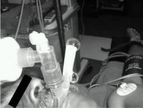
This clinical photograph demonstrates a ProSeal Laryngeal Mask Airway (PLMA) in situ on a patient, illustrating the 'gel displacement test' for airway seal evaluation. The airway management apparatus consists of a primary ventilation tube and a secondary, parallel gastric drain tube exiting the patient's mouth. In the image, a column of clear, water-soluble lubricant gel is visible within the proximal end of the gastric drain tube. The test is used to detect leaks; during positive pressure ventilation, the displacement or ejection of this gel column signifies an incompetent seal at the hypopharynx or malposition of the device's distal cuff. This procedural image highlights a critical bedside assessment technique in anesthesiology and emergency medicine to ensure correct supraglottic airway placement and the separation of respiratory and gastrointestinal tracts. The patient is also shown with standard monitoring equipment, including an ECG electrode and a blood pressure cuff.
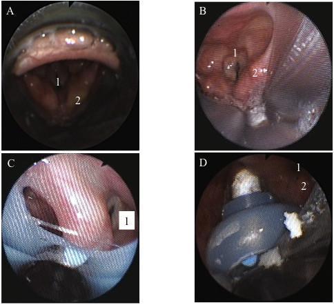
This set of four fiberscopic images (A-D) illustrates the anatomical positioning of various supraglottic airway (SGA) devices relative to the larynx. Panel A shows the i-gel™ device with the glottic inlet (1) and arytenoids (2) clearly visible; the epiglottis is notably resting inside the mask bowl. Panel B displays the LMA-Supreme™, showing similar anatomical landmarks but with visible narrowing of the vocal cords and slightly hyperemic tissue. Panels C and D demonstrate laryngeal views with the Laryngeal Tube Suction-D (LTS-D) in situ. These views illustrate suboptimal or 'awkward' positioning where the device partially obscures the glottic structures, although ventilation remains possible. Across all images, the laryngeal mucosa appears pink and moist, indicating healthy tissue perfusion. This comparative series serves as an educational tool for anesthesiology and emergency medicine to understand how different SGA designs impact glottic visualization and airway alignment during clinical practice.
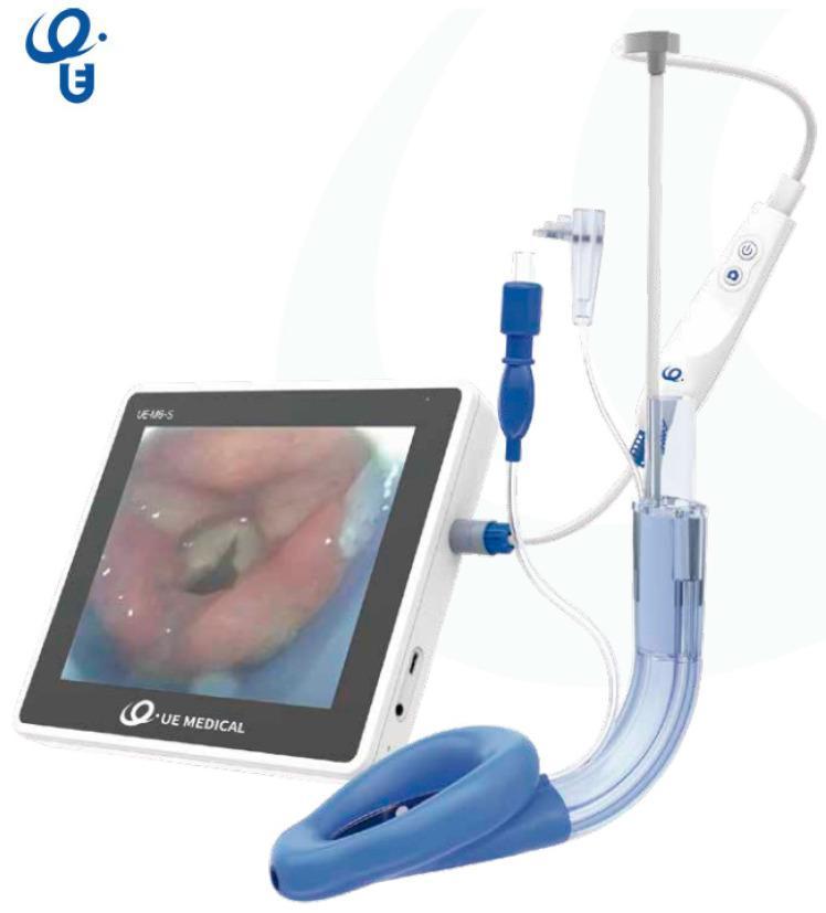
This clinical photograph displays the SaCoVLM video laryngeal mask airway (LMA) system, a specialized supraglottic airway device designed for visualization during airway management. The assembly consists of a curved, semi-transparent breathing tube terminating in a blue, inflatable anatomical mask cuff. Integrated into the device is a video stylus system connected to a handheld control unit with power and capture buttons. Multiple access ports are visible along the tube, including a central channel for gas exchange or endotracheal tube (ETT) insertion, a gastric drainage port, and ports for pressure monitoring and CPAP ventilation. The handheld unit is tethered via a blue connector to a 7-inch portable monitor. The monitor screen displays a high-definition endoscopic view of the glottis, showing the vocal cords and epiglottis, which allows for real-time visual confirmation of device placement and facilitates rescue intubation. This medical technology is utilized by anesthesiologists and emergency physicians to secure the human airway while providing direct visualization of the larynx.
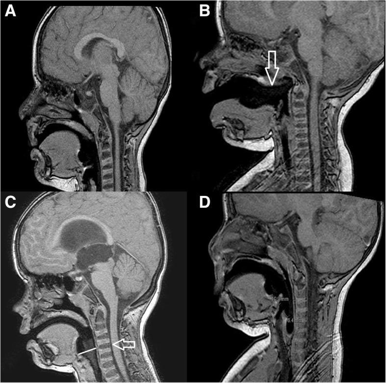
This set of four sagittal T1-weighted MRI images (A, B, C, and D) illustrates the radiological evaluation of laryngeal mask airway (LMA) placement in pediatric patients. Image A displays the radiologically correct position, with the LMA tip seated in the hypopharynx and the proximal cuff aligned with the C1-C2 cervical vertebrae. In contrast, images B, C, and D demonstrate different types of malposition. Image B (Malposition A) shows the mask displaced anteriorly, pointed out by a white arrow, indicating it is outside the hypopharynx. Image C (Malposition B) shows the proximal cuff positioned inferiorly to the C1-C2 level, with a white arrow highlighting the vertebral misalignment. Image D (Malposition C) presents a malposition characterized by spatial measurement discrepancies, where the distance from the proximal cuff to the aditus laryngis (10.9 mm) exceeds the distance from the distal cuff to the aditus laryngis (6.4 mm). These images serve as an educational tool for anesthesiologists to identify anatomical landmarks such as the soft palate, tongue base, and cervical spine relative to supraglottic airway devices.
Newer Supraglottic Airway Devices (SADs)
Definition and Overview
- Advantages: Ease/speed of placement, haemodynamic stability, reduced anaesthetic requirements, no muscle relaxation needed, avoidance of trauma from intubation (teeth, sore throat, laryngospasm on emergence)
- Disadvantages: Lower seal pressures than ETTs, no protection from laryngospasm, and (for first-generation devices) limited protection from gastric regurgitation and aspiration
Classification of SADs
| Class | Mechanism | Examples |
|---|---|---|
| Perilaryngeal sealers | Cuffed, seal around laryngeal inlet | LMA Classic, ProSeal, Supreme, Flexible, Unique |
| Cuffless anatomically preshaped sealers | Shape-based seal, no cuff | i-gel, SLIPA, Baska Mask |
| Cuffed pharyngeal sealers | Cuff at base of tongue ± esophageal cuff | Combitube, King LT, CobraPLA |
1. LMA Classic (cLMA) - First Generation
- Oval silicone mask with inflatable cuff sitting in the hypopharynx, sealed around periglottic tissues
- Airway tube exits mouth with standard 15-mm connector
- PPV up to 20 cm H2O seal pressure
- Reusable up to 40 times; sizes 1 (neonate) to 6 (large adult >100 kg)
- Ideally bordered: base of tongue (superior), pyriform sinuses (lateral), upper esophageal sphincter (inferior)
2. LMA ProSeal (PLMA) - Second Generation
- First second-generation SGA
- Features:
- Additional posterior cuff - improves perilaryngeal seal
- PPV up to 30 cm H2O (vs. 20 cm H2O for cLMA)
- Integrated gastric drainage tube - accepts an orogastric tube, channels regurgitated contents away from the airway - effectively separates respiratory and GI tracts
- Incorporated bite block; softer cuff
- Requires deeper anaesthesia for insertion
- Confirmation of position: gel displacement test (lubricant placed over drain tube orifice - suprasternal notch palpation moves gel but PPV should not)
3. LMA Supreme (SLMA) - Second Generation
- Single-use second-generation SGA
- Features:
- Pre-curved, anatomically shaped rigid airway tube (no need to shape)
- Improved cuff design - higher airway leak pressures
- Gastric drainage tube for gastric access
- Integrated bite block
- Fixation tab for sizing confirmation (should rest 1-2.5 cm above upper lip); taping cheek-to-cheek improves perilaryngeal seal
- Advantage of combining disposability with second-generation features
4. LMA Flexible
- Flexible, kink-resistant wire-reinforced airway tube
- Tube can be positioned away from the surgical field - ideal for head and neck, ENT, and oral procedures
- Available in reusable and single-use models
5. i-gel (Cuffless Anatomically Preshaped - Second Generation)
- Made of soft, thermoplastic elastomer that conforms to hypopharyngeal anatomy - no inflatable cuff
- Advantages: Eliminates cuff pressure complications (nerve palsies, tissue necrosis); simple insertion
- Contains a gastric drain port and provides higher seal pressures - classified as second-generation
- Colour-coded by size for quick selection
- Particularly useful in emergency/prehospital settings due to simplicity
6. Intubating LMA / Fastrach (ILMA) - Conduit Device
- Specifically designed to facilitate blind or fibreoptic-guided tracheal intubation through the LMA
- Features:
- Rigid, curved airway tube (guiding handle allows single-hand insertion)
- Epiglottic elevating bar to lift the epiglottis
- Accommodates a dedicated 8.0 mm silicone-cuffed ETT
- Modified proximal end allows ETT removal of ILMA while leaving ETT in trachea (using a stabilising rod)
- Success rate for blind intubation: ~95-99%
- Critical rescue device in the cannot-intubate-cannot-oxygenate (CICO) scenario
7. LMA CTrach
- Modification of the ILMA incorporating a fibreoptic camera and detachable LCD viewer
- Allows real-time visualisation of vocal cords and passage of ETT
- Combines intubating LMA with video technology
8. Esophageal-Tracheal Combitube (ETC) - Cuffed Pharyngeal Sealer
- Two-lumen, two-cuff device
- Two lumina: long blue #1 (esophageal lumen with closed tip + side perforations) and short clear #2 (tracheal lumen)
- Two cuffs: proximal oropharyngeal cuff (100 mL) and distal esophageal-tracheal cuff (15 mL)
- Esophageal placement occurs ~95% of the time - ventilate via the blue lumen (gas exits side perforations into larynx)
- If tracheal placement: ventilate via clear lumen
- Uses: primarily prehospital emergency intubation; not recommended for paediatrics; contains latex (avoid in latex-sensitive patients)
- Higher complication rate than LMA (hoarseness, dysphagia, bleeding)
9. King Laryngeal Tube (King LT)
- Similar design to the ETC - single ventilation lumen with pharyngeal and oesophageal cuffs
- Both cuffs inflate via one inflation line (simpler than ETC)
- Gas exits between the two cuffs, directed into the larynx
- Suction port distal to esophageal balloon for gastric decompression
- If ventilation is difficult after inflation, device is too deep - slowly withdraw until compliance improves
- King LT-D: disposable version; King LTS-D: with gastric suction port
10. Newer Innovations
- SLIPA (Streamlined Liner of the Pharynx Airway): Cuffless, preshaped hollow device; hollow chamber traps regurgitated liquid, potentially preventing aspiration
- Baska Mask: Cuffless second-generation device with self-sealing mechanism
- air-Q SP (Self-Pressurising): Cuff pressurises using patient's own positive pressure ventilation; deflates during exhalation, reducing cumulative mucosal pressure
- SaCoVLM (Video LMA): Integrated video stylus + external monitor; provides real-time glottic visualisation and facilitates rescue ETT passage
Sizing (LMA)
| Size | Patient | Weight |
|---|---|---|
| 1 | Neonate | <6.5 kg |
| 2 | Child | 6.5-20 kg |
| 2.5 | Child | 20-30 kg |
| 3 | Small adult | >30 kg |
| 4 | Normal adult (female) | <70 kg |
| 5 | Larger adult (male) | >70 kg |
Contraindications to SADs (LMA)
- Full stomach / aspiration risk (pregnancy, hiatal hernia, bowel obstruction)
- Pharyngeal pathology (abscess, tumour, limited mouth opening)
- Low pulmonary compliance requiring peak inspiratory pressures >30 cm H2O
- Laryngospasm (SGAs do not protect against it)
Complications
- Sore throat (10-20% incidence) - linked to high cuff pressures and large sizes
- Lingual, hypoglossal, recurrent laryngeal nerve palsies (usually self-limiting)
- Uvular trauma, pharyngeal necrosis (rare)
- Prevention: Correct sizing, avoid cuff hyperinflation (keep <60 cm H2O), adequate lubrication, N2O causes cuff pressure rise (monitor periodically)
Role in Difficult Airway
- Rescue airway when mask ventilation and intubation both fail (CICO)
- Conduit for tracheal intubation (ILMA, air-Q, LMA Unique EVO)
- Bridge to awake fibreoptic intubation
- First-line airway for diagnostic/minor surgical procedures
Add reference photos with each
LMA Classic laryngeal mask airway insertion technique
This clinical photograph displays the SaCoVLM video laryngeal mask airway (LMA) system, a specialized supraglottic airway device designed for visualization during airway management. The assembly consists of a curved, semi-transparent breathing tube terminating in a blue, inflatable anatomical mask cuff. Integrated into the device is a video stylus system connected to a handheld control unit with power and capture buttons. Multiple access ports are visible along the tube, including a central channel for gas exchange or endotracheal tube (ETT) insertion, a gastric drainage port, and ports for pressure monitoring and CPAP ventilation. The handheld unit is tethered via a blue connector to a 7-inch portable monitor. The monitor screen displays a high-definition endoscopic view of the glottis, showing the vocal cords and epiglottis, which allows for real-time visual confirmation of device placement and facilitates rescue intubation. This medical technology is utilized by anesthesiologists and emergency physicians to secure the human airway while providing direct visualization of the larynx.
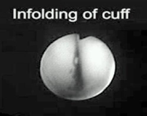
This endoscopic or clinical image illustrates a specific malposition of a laryngeal mask airway (LMA) known as cuff infolding. The visual demonstrates an inflated cuff that has lost its normal elliptical shape; the lateral margins of the cuff have rotated inward toward the center. This inward rotation causes the two sides of the cuff to meet and contact at the midline, creating a prominent vertical groove or division that bisects the structure. This configuration effectively obliterates the central bowl area, which is intended to facilitate gas flow into the laryngeal inlet. Such malposition typically occurs during insertion or as a result of pre-insertion over-inflation, leading to mechanical airway obstruction. The image is an essential educational resource for anesthesiologists and airway management specialists to recognize the visual signs of improper LMA placement and distinguish it from other complications like epiglottic downfolding.
LMA ProSeal second generation gastric drain tube
This clinical photograph demonstrates a ProSeal Laryngeal Mask Airway (PLMA) in situ on a patient, illustrating the 'gel displacement test' for airway seal evaluation. The airway management apparatus consists of a primary ventilation tube and a secondary, parallel gastric drain tube exiting the patient's mouth. In the image, a column of clear, water-soluble lubricant gel is visible within the proximal end of the gastric drain tube. The test is used to detect leaks; during positive pressure ventilation, the displacement or ejection of this gel column signifies an incompetent seal at the hypopharynx or malposition of the device's distal cuff. This procedural image highlights a critical bedside assessment technique in anesthesiology and emergency medicine to ensure correct supraglottic airway placement and the separation of respiratory and gastrointestinal tracts. The patient is also shown with standard monitoring equipment, including an ECG electrode and a blood pressure cuff.
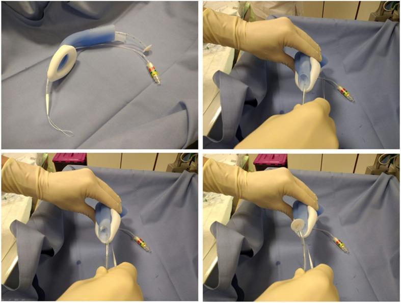
A four-panel sequence of intraoperative clinical photographs demonstrating the use of the LMA Gastro™ supraglottic airway device during a percutaneous endoscopic gastrostomy (PEG) procedure. The top-left image shows the standalone device on a sterile blue surgical drape, highlighting its dual-channel design: a curved airway tube and a secondary, wide-bore gastric channel intended for endoscopic access. Key components visible include the inflatable distal cuff, an integrated proximal bite block, and two pilot balloon inflation lines with color-coded connectors. The remaining three panels show a healthcare provider’s gloved hands manipulating the device to demonstrate the 'pull' technique. A white gastroduodenoscope or pull-wire is shown being threaded through the large gastric channel of the LMA. This visual illustrates the device's utility in providing simultaneous positive pressure ventilation and unhindered endoscopic access to the upper gastrointestinal tract, facilitating advanced procedures like PEG in patients under general anesthesia.
LMA Supreme single use supraglottic airway fixation tab
A four-panel sequence of intraoperative clinical photographs demonstrating the use of the LMA Gastro™ supraglottic airway device during a percutaneous endoscopic gastrostomy (PEG) procedure. The top-left image shows the standalone device on a sterile blue surgical drape, highlighting its dual-channel design: a curved airway tube and a secondary, wide-bore gastric channel intended for endoscopic access. Key components visible include the inflatable distal cuff, an integrated proximal bite block, and two pilot balloon inflation lines with color-coded connectors. The remaining three panels show a healthcare provider’s gloved hands manipulating the device to demonstrate the 'pull' technique. A white gastroduodenoscope or pull-wire is shown being threaded through the large gastric channel of the LMA. This visual illustrates the device's utility in providing simultaneous positive pressure ventilation and unhindered endoscopic access to the upper gastrointestinal tract, facilitating advanced procedures like PEG in patients under general anesthesia.
This clinical photograph displays the SaCoVLM video laryngeal mask airway (LMA) system, a specialized supraglottic airway device designed for visualization during airway management. The assembly consists of a curved, semi-transparent breathing tube terminating in a blue, inflatable anatomical mask cuff. Integrated into the device is a video stylus system connected to a handheld control unit with power and capture buttons. Multiple access ports are visible along the tube, including a central channel for gas exchange or endotracheal tube (ETT) insertion, a gastric drainage port, and ports for pressure monitoring and CPAP ventilation. The handheld unit is tethered via a blue connector to a 7-inch portable monitor. The monitor screen displays a high-definition endoscopic view of the glottis, showing the vocal cords and epiglottis, which allows for real-time visual confirmation of device placement and facilitates rescue intubation. This medical technology is utilized by anesthesiologists and emergency physicians to secure the human airway while providing direct visualization of the larynx.
i-gel supraglottic airway device cuffless thermoplastic
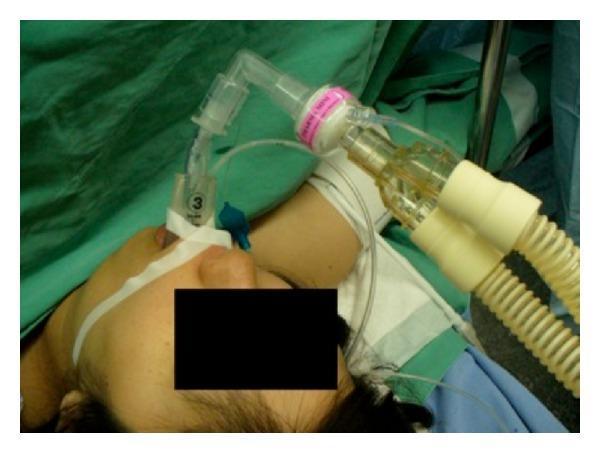
This clinical photograph illustrates a complex airway management setup in an anesthetized patient. A size 3 I-gel supraglottic airway device is positioned in the oropharynx and secured with white adhesive tape across the patient's face. Inserted through the I-gel is a Parker tracheal tube, demonstrating the use of a supraglottic device as a conduit for endotracheal intubation. The airway circuit includes a clear right-angled connector attached to a Heat and Moisture Exchange (HME) filter (pink and white), which subsequently connects to a dual-limb corrugated ventilator breathing circuit. A thin nasogastric tube is visible, running alongside the airway equipment through the gastric channel of the I-gel for gastric decompression. This image is medically significant for teaching advanced airway techniques, specifically the transition from a supraglottic airway to definitive tracheal intubation under general anesthesia in a surgical setting.
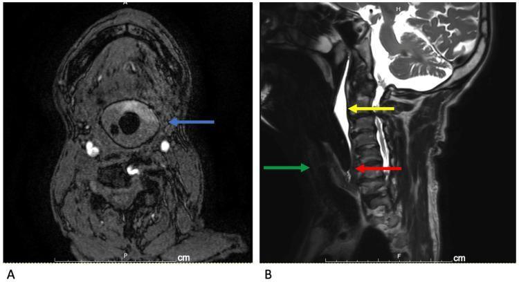
This diagnostic imaging composite displays a comparison of an i-gel supraglottic airway device in situ via MRI. Image A is a horizontal MRI angiography section showing the i-gel (blue arrow) creating a complete, circular seal within the hypopharynx. The central lumen of the device appears as a low-signal (dark) circular void, surrounded by the intermediate-signal material of the device's cuff, which interfaces tightly with the surrounding pharyngeal soft tissues. Image B is a T2-weighted sagittal MRI of the cervical spine and airway. It illustrates the spatial relationship of the device: the glottis is marked by a green arrow, the high-signal (bright) accumulation of saliva is sequestered posterior to the tongue and superior to the device cuff (yellow arrow), and the distal tip of the i-gel is positioned near the upper esophageal sphincter (red arrow). The images demonstrate the device's anatomical fit, airway patency, and effective separation of secretions from the laryngeal inlet, which is critical for airway management during general anesthesia in the MRI suite.
intubating LMA Fastrach ILMA endotracheal tube insertion
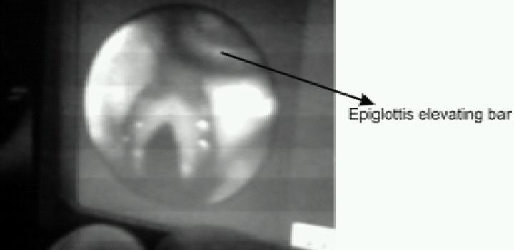
A fiberoptic endoscopic view of the larynx obtained through an LMA CTrach system. The circular field of view captures the glottic opening, including the laryngeal inlet and vocal cords positioned centrally. An arrow labels the 'Epiglottis elevating bar,' a mechanical component of the LMA CTrach device visible at the top of the frame. This bar is designed to lift the epiglottis away from the glottis to facilitate visualization and subsequent passage of an endotracheal tube (ETT). The image demonstrates the internal anatomical orientation required for successful blind or visually-guided intubation using a supraglottic airway with integrated fiberoptic channels. The educational focus is on the clinical application of airway management devices and the recognition of laryngeal structures through a video-assisted intubating laryngeal mask airway.
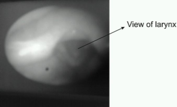
This diagnostic endoscopy image, captured via an LMA CTrach system, displays a grayscale view of the laryngeal structures as seen on an LCD monitor. The image features a circular field of view centered on the laryngeal inlet. Anatomically, the vocal cords are discernible as lighter linear contours positioned centrally, bordered by the darker aperture of the glottis. An arrow indicates the 'View of larynx,' highlighting the primary target area for endotracheal tube insertion. The visualization is achieved through fiberoptic channels integrated into the Laryngeal Mask Airway (LMA), designed to provide real-time guidance during tracheal intubation. The grayscale contrast helps identify the orientation of the epiglottis elevating bar relative to the glottic opening, which is essential for successful airway management and clinical training in anesthesiology and emergency medicine.
esophageal tracheal combitube two lumen emergency airway
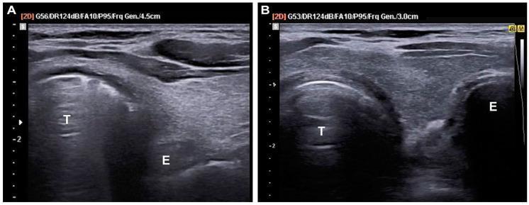
This comparison set of transverse trans-tracheal ultrasound (TTUS) images illustrates sonographic signs used to confirm endotracheal tube placement. Image A demonstrates successful tracheal intubation, characterized by the 'comet tail sign' within the tracheal lumen (T). This reverberation artifact is created by the interface of air and the endotracheal tube. The esophagus (E) remains a collapsed, hypoechoic structure lateral to the trachea. Image B demonstrates an esophageal intubation, evidenced by the 'double ring sign.' In this case, two circular, air-filled structures are visible side-by-side: the anatomical trachea (T) and the distended esophagus (E) containing the misplaced endotracheal tube. Key diagnostic landmarks include the hyperechoic anterior tracheal wall and the relative positioning of the esophagus. These images are essential for emergency medicine and anesthesiology training for rapid, point-of-care airway management verification during cardiac arrest or respiratory failure scenarios.
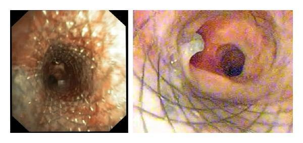
Two-panel bronchoscopic clinical photograph showing the management of a tracheoesophageal fistula (TEF). The left panel displays a diagnostic view of the tracheal lumen, where a previously placed esophageal self-expanding metallic stent (SEMS) has eroded through the posterior tracheal wall, evidenced by the visible wire mesh protruding into the airway and causing tissue irregularity. The right panel demonstrates the post-procedural outcome following the successful deployment of a covered tracheal SEMS. This second stent successfully bridges and seals the TEF and the site of erosion. The lumen of the newly placed covered stent is patent, with a smooth internal surface that restores airway integrity and isolates the trachea from the esophageal defect. The surrounding tracheal mucosa shows mild reactive erythema and inflammation consistent with chronic irritation from the fistula and metallic hardware.
King laryngeal tube airway pharyngeal esophageal balloons
An intraoperative endoscopic view of the larynx and posterior pharyngeal region during a surgical repair of a laryngeal cleft. The image demonstrates a fresh, longitudinal incision made along the mucosal border of the interarytenoid area, extending toward the esophageal inlet. The vocal cords are visible as whitish, longitudinal bands flanking the airway opening. The surgical site displays characteristic signs of recent intervention, including focal erythema, disrupted tissue margins with a raw texture, and small amounts of serosanguinous fluid and bubbles, likely from irrigation or needle-tip electrocautery denudation. This image illustrates a critical preparatory step in laryngeal cleft closure—creating fresh, denuded wound edges to facilitate subsequent primary suturing and tissue apposition. The visual focus is on the anatomical relationship between the laryngeal airway, the posterior cleft, and the adjacent esophageal opening in a pediatric or clinical context.
Side-by-side lateral view radiographic images from a postoperative barium swallow study demonstrating normal pharyngeal swallowing mechanics. Image (a) captures the early pharyngeal phase, highlighting the anatomical interval (double-headed arrow) between the cricoid cartilage and the cervical spine following the resection of a synostosis. A solid horizontal line marks the baseline height of the superior cricoid cartilage. Image (b) shows the late pharyngeal-early esophageal phase. Successful airway protection is indicated by the absence of contrast material in the trachea (arrowheads). Improved laryngeal elevation is visually quantified by comparing the new superior position of the cricoid (solid line) against its starting position (dotted line). The images serve as clinical evidence of restored swallowing function, showing proper bolus transit into the esophagus without aspiration after surgical intervention for dysphagia.
LMA cuff malposition infolding airway obstruction
This endoscopic or clinical image illustrates a specific malposition of a laryngeal mask airway (LMA) known as cuff infolding. The visual demonstrates an inflated cuff that has lost its normal elliptical shape; the lateral margins of the cuff have rotated inward toward the center. This inward rotation causes the two sides of the cuff to meet and contact at the midline, creating a prominent vertical groove or division that bisects the structure. This configuration effectively obliterates the central bowl area, which is intended to facilitate gas flow into the laryngeal inlet. Such malposition typically occurs during insertion or as a result of pre-insertion over-inflation, leading to mechanical airway obstruction. The image is an essential educational resource for anesthesiologists and airway management specialists to recognize the visual signs of improper LMA placement and distinguish it from other complications like epiglottic downfolding.
This set of four sagittal T1-weighted MRI images (A, B, C, and D) illustrates the radiological evaluation of laryngeal mask airway (LMA) placement in pediatric patients. Image A displays the radiologically correct position, with the LMA tip seated in the hypopharynx and the proximal cuff aligned with the C1-C2 cervical vertebrae. In contrast, images B, C, and D demonstrate different types of malposition. Image B (Malposition A) shows the mask displaced anteriorly, pointed out by a white arrow, indicating it is outside the hypopharynx. Image C (Malposition B) shows the proximal cuff positioned inferiorly to the C1-C2 level, with a white arrow highlighting the vertebral misalignment. Image D (Malposition C) presents a malposition characterized by spatial measurement discrepancies, where the distance from the proximal cuff to the aditus laryngis (10.9 mm) exceeds the distance from the distal cuff to the aditus laryngis (6.4 mm). These images serve as an educational tool for anesthesiologists to identify anatomical landmarks such as the soft palate, tongue base, and cervical spine relative to supraglottic airway devices.
supraglottic airway MRI placement anatomy hypopharynx
This diagnostic imaging composite displays a comparison of an i-gel supraglottic airway device in situ via MRI. Image A is a horizontal MRI angiography section showing the i-gel (blue arrow) creating a complete, circular seal within the hypopharynx. The central lumen of the device appears as a low-signal (dark) circular void, surrounded by the intermediate-signal material of the device's cuff, which interfaces tightly with the surrounding pharyngeal soft tissues. Image B is a T2-weighted sagittal MRI of the cervical spine and airway. It illustrates the spatial relationship of the device: the glottis is marked by a green arrow, the high-signal (bright) accumulation of saliva is sequestered posterior to the tongue and superior to the device cuff (yellow arrow), and the distal tip of the i-gel is positioned near the upper esophageal sphincter (red arrow). The images demonstrate the device's anatomical fit, airway patency, and effective separation of secretions from the laryngeal inlet, which is critical for airway management during general anesthesia in the MRI suite.
This set of four sagittal T1-weighted MRI images (A, B, C, and D) illustrates the radiological evaluation of laryngeal mask airway (LMA) placement in pediatric patients. Image A displays the radiologically correct position, with the LMA tip seated in the hypopharynx and the proximal cuff aligned with the C1-C2 cervical vertebrae. In contrast, images B, C, and D demonstrate different types of malposition. Image B (Malposition A) shows the mask displaced anteriorly, pointed out by a white arrow, indicating it is outside the hypopharynx. Image C (Malposition B) shows the proximal cuff positioned inferiorly to the C1-C2 level, with a white arrow highlighting the vertebral misalignment. Image D (Malposition C) presents a malposition characterized by spatial measurement discrepancies, where the distance from the proximal cuff to the aditus laryngis (10.9 mm) exceeds the distance from the distal cuff to the aditus laryngis (6.4 mm). These images serve as an educational tool for anesthesiologists to identify anatomical landmarks such as the soft palate, tongue base, and cervical spine relative to supraglottic airway devices.
Newer Supraglottic Airway Devices (SADs)
Definition and Overview
| Generation | Class | Key Feature |
|---|---|---|
| 1st | Perilaryngeal sealers | Inflatable cuff, seal around laryngeal inlet |
| 1st | Cuffless preshaped sealers | Anatomical shape provides seal |
| 1st/2nd | Cuffed pharyngeal sealers | Cuff at base of tongue ± esophageal cuff |
| 2nd | Second-generation | Gastric drain port + higher seal pressure |
1. LMA Classic (cLMA) - First Generation Perilaryngeal Sealer
- Oval silicone mask with inflatable cuff sitting in the hypopharynx
- Sealed around periglottic tissues (base of tongue superiorly, pyriform sinuses laterally, upper esophageal sphincter inferiorly)
- 15-mm standard connector; PPV up to 20 cm H2O
- Sizes 1 (neonate) to 6 (large adult >100 kg); reusable up to 40 times
- Success rate 95-99%
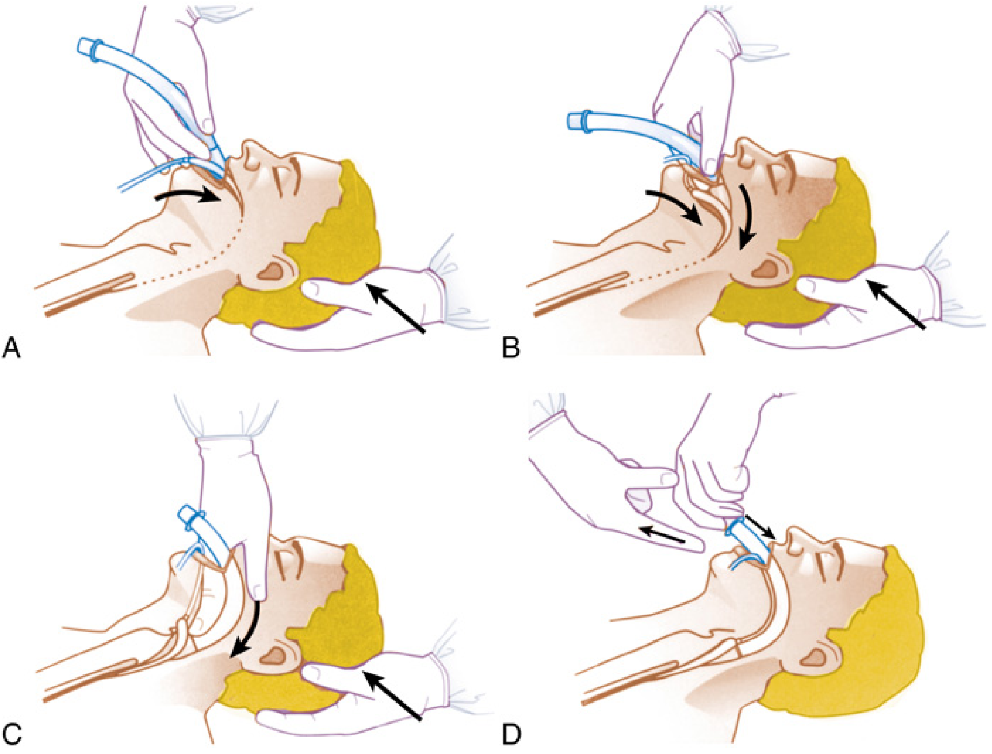
2. LMA ProSeal (PLMA) - Second Generation
- Additional posterior cuff - improves perilaryngeal seal
- Seal pressure up to 30 cm H2O (vs. 20 for cLMA)
- Gastric drainage tube - isolates respiratory from GI tract; accepts orogastric tube
- Integrated bite block; softer cuff
- Gel displacement test confirms placement: lubricant placed in drain tube orifice - suprasternal notch palpation moves gel; PPV must NOT
3. LMA Supreme (SLMA) - Second Generation, Single-Use
- Pre-curved rigid airway tube (anatomically shaped - no manual shaping needed)
- Improved cuff = higher airway leak pressures than cLMA
- Gastric drainage channel for gastric access
- Integrated bite block + fixation tab (tab rests 1-2.5 cm above upper lip; tape cheek-to-cheek for improved seal)
- Advantage: combines single-use hygiene with second-generation aspiration protection
4. LMA Flexible
- Wire-reinforced, kink-resistant, flexible airway tube
- Tube redirects away from the surgical field - ideal for ENT, head and neck, and oral/dental procedures
- Available in reusable and single-use models
5. i-gel - Cuffless Anatomically Preshaped (Second Generation)
- Made of soft non-inflatable thermoplastic elastomer that moulds to hypopharyngeal anatomy
- No inflatable cuff - eliminates cuff pressure complications (nerve palsies, tissue necrosis, overinflation)
- Has a gastric drain port + produces high seal pressures = classified second-generation
- Colour-coded by size; stem bite block
- Simple, rapid insertion - popular in emergency/prehospital/resuscitation settings
6. Intubating LMA / LMA Fastrach (ILMA) - Conduit Device
- Rigid curved tube with guiding handle for single-hand insertion
- Epiglottis elevating bar lifts epiglottis away from the glottis
- Accommodates a dedicated 8.0 mm silicone ETT
- ETT can be left in trachea while ILMA is removed over it using a stabilising rod
- Blind intubation success rate ~95-99%
- Role: CICO (cannot intubate, cannot oxygenate) rescue scenario
7. LMA CTrach - Video-Assisted Intubating LMA
- Modification of the ILMA incorporating integrated fibreoptic channels + detachable LCD viewer
- Provides real-time visualisation of vocal cords for guided ETT passage
- Combines intubating LMA functionality with video technology
8. Esophageal-Tracheal Combitube (ETC) - Cuffed Pharyngeal Sealer
- Two lumina + two cuffs device
- Lumen 1 (long, blue): closed distal tip + side perforations between the two cuffs
- Lumen 2 (short, clear): open distal tip
- Proximal oropharyngeal cuff (100 mL) + distal esophageal-tracheal cuff (15 mL)
- Inserted blindly; esophageal placement ~95% of the time - ventilate via blue lumen (gas exits perforations into larynx)
- If tracheal placement: ventilate via clear lumen
- Primarily prehospital emergency use; contains latex; higher complication rate (hoarseness, dysphagia, bleeding)
- Not for paediatrics; not for latex-sensitive patients
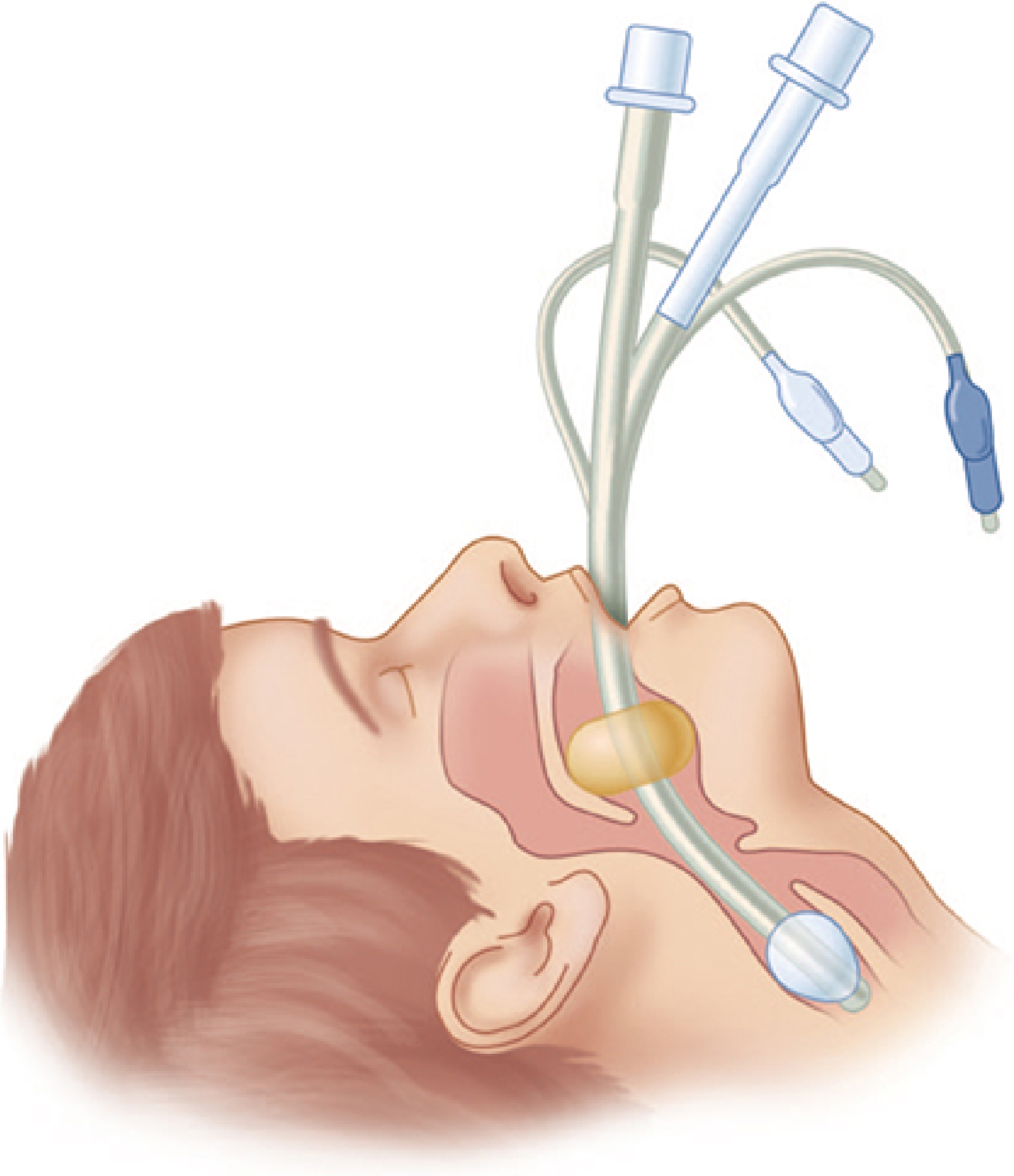
9. King Laryngeal Tube (King LT)
- Similar to ETC but single ventilation lumen (simpler)
- Both pharyngeal + esophageal cuffs inflate via one inflation line
- Gas exits between the two cuffs, directed into the larynx
- Suction port distal to esophageal balloon for gastric decompression
- If ventilation difficult after inflation = device too deep - slowly withdraw until compliance improves
- King LT-D (disposable); King LTS-D (with suction port)
10. SaCoVLM (Video Laryngeal Mask Airway) - Newest Generation
- Integrated video stylus system + external 7-inch portable monitor
- Real-time glottic visualisation during placement + ETT guidance
- Central gas exchange channel, gastric drainage port, pressure monitoring port
- Represents fusion of SGA and videolaryngoscopy technology
Comparison of Fiberscopic Views - i-gel vs LMA Supreme vs King LT
LMA Cuff Malposition - What to Recognise
Sizing Reference (LMA)
| Size | Patient | Weight |
|---|---|---|
| 1 | Neonate | <6.5 kg |
| 2 | Child | 6.5-20 kg |
| 2.5 | Child | 20-30 kg |
| 3 | Small adult | >30 kg |
| 4 | Normal adult / female | <70 kg |
| 5 | Larger adult / male | >70 kg |
Complications and Prevention
- Sore throat (10-20%) - linked to high cuff pressure and large sizes
- Nerve injury (lingual, hypoglossal, recurrent laryngeal) - usually resolve over weeks-months
- Uvular trauma, pharyngeal necrosis (rare)
- N2O diffusion into cuff - periodically check cuff pressure intraoperatively
- Prevention: correct sizing, cuff pressure <60 cm H2O, adequate lubrication, avoid hypopharyngeal manipulation when inserting
Role in Difficult Airway (ASA DAA)
- Rescue airway in CICO (cannot intubate, cannot oxygenate)
- Bridge to awake fibreoptic intubation
- Conduit for tracheal intubation (ILMA, CTrach, air-Q, LMA Unique EVO, i-gel)
- First choice for diagnostic and minor surgical procedures