
Lumbar puncture entire procedure for practical skills
lumbar puncture procedure spinal needle positioning
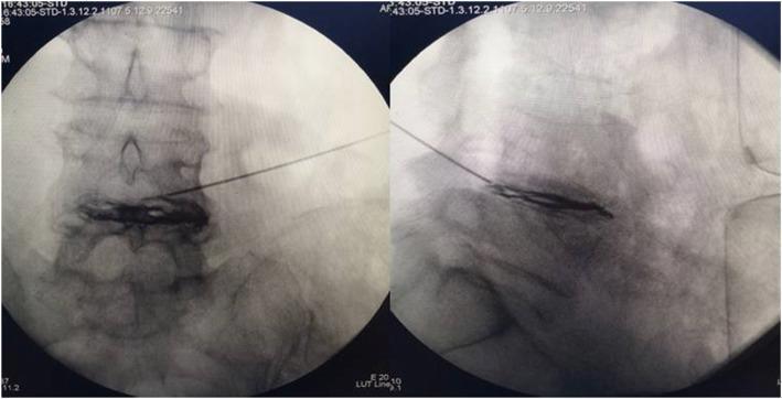
This diagnostic image displays dual-pane intraoperative C-arm fluoroscopy views (anteroposterior and lateral) of the lumbar spine during a minimally invasive spinal procedure. The images demonstrate the precise positioning of a radiofrequency (RF) puncture needle within an intervertebral disc space. In the anteroposterior (AP) view on the left, the needle tip is centered over the disc, with contrast medium appearing as a dark, radiopaque area spreading horizontally within the nucleus pulposus and toward the annulus fibrosus. The lateral view on the right confirms the depth of the needle tip within the center of the disc space, showing the longitudinal distribution of the contrast agent along the superior and inferior vertebral endplates. These images are clinically significant for verifying needle placement and contrast spread during intradiscal radiofrequency thermocoagulation or discography for the treatment of lumbar disc herniation. The modality is fluoroscopic guided intervention, highlighting anatomical landmarks including vertebral bodies, pedicles, and the intervertebral disc interval.
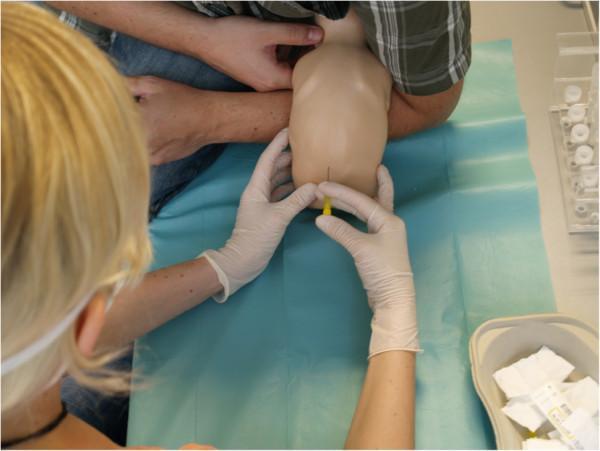
This clinical photograph depicts a simulated infant lumbar puncture procedure performed in a medical skills laboratory setting. The image shows a medical trainee wearing white sterile gloves and a mask, positioned to insert a yellow-hubbed spinal needle into the lower back of an infant mannequin. The mannequin is placed in a lateral decubitus (side-lying) position on a blue surgical drape, with an assistant's hands visible stabilizing the upper torso and limbs to maintain the necessary spinal flexion. Surrounding the procedural field are various medical supplies, including a kidney dish containing sterile gauze and swabs, and organized containers with sample vials or additional equipment. The focus of the visual is on the anatomical landmarks of the lumbar spine and the correct hand positioning for needle insertion. This educational material is designed to demonstrate paediatric procedural skills, aseptic technique, and proper patient positioning for cerebrospinal fluid collection or diagnostic testing in neonatal and paediatric medicine.
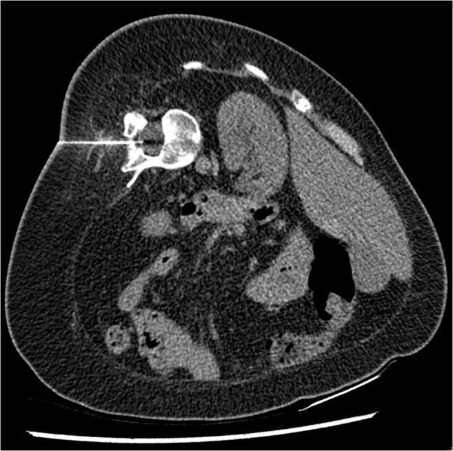
An axial non-contrast CT scan of the abdomen and lower lumbar region, demonstrating a CT-guided interventional procedure. The image shows a spinal needle traversing the paraspinal musculature and subcutaneous fat from a left-sided approach. The needle tip is precisely positioned within the spinal canal, targeted for an intrathecal injection (nusinersen) in a patient with Spinal Muscular Atrophy (SMA). The spinal anatomy displays significant rotation and distortion consistent with severe scoliosis. Visible internal landmarks include a vertebral body, the spleen in the right aspect of the image (due to patient positioning), and loops of bowel with speckled fecal content. The image illustrates the standard protocol for neuraxial access in complex anatomical scenarios where traditional palpation-based lumbar puncture is not feasible due to skeletal deformities. Key features include the visualization of the needle trajectory, the clear identification of the target intrathecal space, and the surrounding soft tissue and osseous structures.
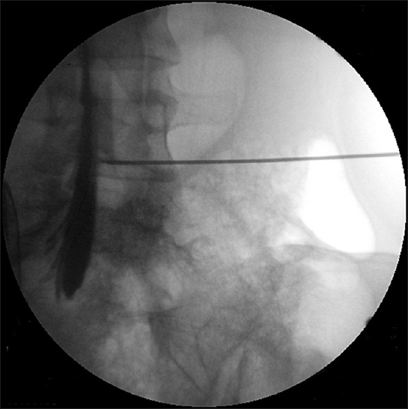
**Imaging Modality:** Intra-operative fluoroscopy (spot film). **Anatomical Region:** Lateral view of the lumbar spine, specifically focusing on the lower lumbar vertebrae and the sacral promontory. **Procedure and Findings:** The image demonstrates a fluoroscopically guided needle placement for a spinal procedure. A radiopaque spinal needle is visible, transversing the soft tissues and terminating within the spinal canal. Intrathecal administration of water-soluble contrast media is evidenced by a distinct, vertical column of radiopacity flowing within the subarachnoid space (myelographic effect). The contrast is seen layering anteriorly and inferiorly along the spinal canal, highlighting the borders of the dural sac. **Key Visual Features:** - **Needle Position:** Lateral approach with the tip localized to the posterior aspect of the vertebral canal. - **Contrast Pattern:** Sharp, linear opacification characteristic of intrathecal (subarachnoid) distribution, rather than the "feathery" or "vacuolated" appearance typical of epidural injection. - **Landmarks:** Lumbar vertebral bodies, intervertebral disc spaces, and the spinous processes are partially visualized. **Clinical Significance:** This image serves as confirmation of needle tip positioning within the intrathecal space during a myelogram, lumbar puncture, or spinal anesthesia procedure.
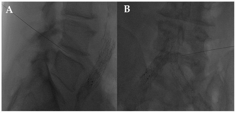
This diagnostic fluoroscopic image set illustrates a lumbar intersomatic disc puncture procedure using a 22G needle, commonly performed for intradiscal injections such as oxygen-ozone (O2-O3) therapy. Image A presents a lateral view of the lumbar spine, demonstrating the needle's trajectory from a posterior-lateral entry point. The needle tip is clearly visualized penetrating the intervertebral disc space between two lumbar vertebrae, positioned centrally within the disc. Image B shows the frontal (anteroposterior) view of the same procedure, highlighting the needle traversing toward the radiolucent gap representing the disc space. The stacked vertebral bodies and their respective endplates serve as critical anatomical landmarks for verifying correct needle placement. Of note, radiopaque vascular stents are visible in the foreground, indicating the patient's comorbidities. This visual serves as an educational guide for image-guided spinal interventions, focusing on the transforaminal or lateral approach to the nucleus pulposus for treating chronic low back pain or disc herniation.
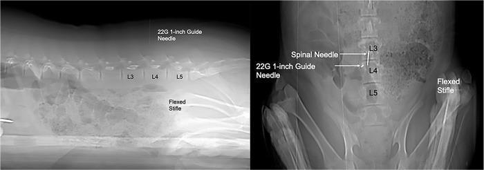
Diagnostic CT scout images (sagittal and dorsal views) demonstrating the procedural localization for a lumbar puncture in a porcine model. The sagittal view (left) shows a 22-gauge, 1-inch guide needle inserted as a radiopaque cutaneous marker. Its placement is localized dorsally between the L3 and L4 lumbar vertebrae, utilizing the cranial border of the flexed stifle as a palpable anatomical landmark. The dorsal view (right) displays the final positioning of the larger spinal needle in relation to the guide needle. Both needles are visible as linear radiopaque densities along the dorsal midline. The spinal needle is positioned cranially to the guide needle, precisely targeting the L3-L4 intervertebral space for subarachnoid access. These views are essential for confirming the longitudinal and midline trajectory before advancing the needle to the floor of the vertebral canal for myelographic contrast injection. Key anatomical landmarks labeled include the L3, L4, and L5 vertebrae and the flexed stifle joint.
lumbar puncture anatomy layers skin to subarachnoid space cross section diagram
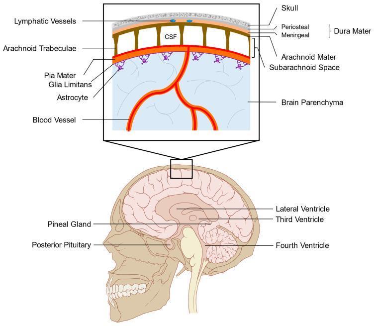
This medical anatomical diagram illustrates the layers of the human meninges and the organization of the subarachnoid space. The lower panel displays a sagittal view of the head, identifying internal structures such as the lateral, third, and fourth ventricles, alongside circumventricular organs including the pineal gland and posterior pituitary. The upper panel provides a high-magnification cross-sectional view of the cranial protective layers. From superficial to deep, it depicts the skull, the dura mater (consisting of periosteal and meningeal layers containing lymphatic vessels), the arachnoid mater, and the subarachnoid space filled with cerebrospinal fluid (CSF). The arachnoid trabeculae are shown spanning the subarachnoid space to connect with the pia mater. Below the pia mater, the glia limitans is illustrated, formed by astrocytic foot processes that interface with the underlying brain parenchyma and cortical blood vessels. This diagram is designed to explain leptomeningeal anatomy and the fluid dynamics between the ventricular system, subarachnoid space, and the blood-brain barrier interface.
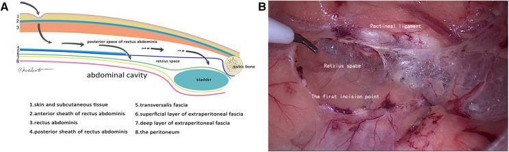
This composite educational material consists of an anatomical diagram (A) and a corresponding intraoperative clinical photograph (B) illustrating the surgical approach to the preperitoneal space during hernia repair. Diagram A provides a sagittal cross-section of the abdominal wall layers, including the skin, rectus abdominis, posterior rectus sheath, transversalis fascia, and peritoneum, highlighting the entry pathway into the Retzius space above the bladder and pubic bone. Intraoperative image B shows the laparoscopic view of the 'first incision point' within the transversalis fascia, located approximately 1 cm above the pectineal ligament (Cooper's ligament). The Retzius space is visible as a cavitary area with glistening, translucent connective tissue and fibrous networks. The pectineal ligament is identified as a distinct whitish band at the superior margin. This visual material is designed for surgical trainees to understand the 'transversalis fascia reference plane' and membrane anatomy during Totally Extraperitoneal (TEP) laparoscopic hernia repair, emphasizing safe entry into the Retzius space to avoid vascular or bladder injury.
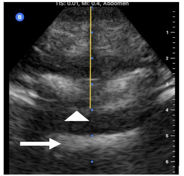
This diagnostic ultrasound image demonstrates spinal anatomy in a transverse view, likely used for neuraxial anesthesia planning or a lumbar puncture. The image features two key anatomical landmarks: the posterior complex (marked by a white arrowhead), which consists of the ligamentum flavum, the epidural space, and the posterior dura mater; and the anterior complex (marked by a white arrow), representing the posterior longitudinal ligament and the vertebral body. The posterior complex appears as a layered, hyperechoic structure superior to the intrathecal space. A vertical yellow caliper line with blue dots extends from the skin surface to the posterior complex, measuring the skin-to-ligamentum flavum distance, which is critical for determining appropriate needle depth. The ultrasound shows typical tissue echogenicity variations, with subcutaneous fat and muscle layers visible superficial to the spinal structures. This visual is an essential educational tool for understanding ultrasound-guided identification of the epidural and subarachnoid spaces.
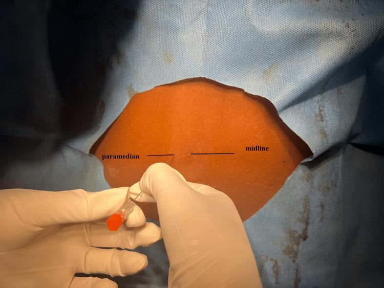
A clinical photograph depicting a patient's lower back prepared for a neuraxial procedure, likely a spinal anesthesia or lumbar puncture. The patient is draped in blue sterile material with a central rectangular exposure of the skin. Two black horizontal line markers are visible on the skin, labeled 'midline' and 'paramedian' to distinguish between different technical approaches to the subarachnoid space. A medical professional, wearing sterile white gloves, is shown inserting a spinal needle through the skin. The needle features an orange-coded hub, typically indicating a 25-gauge needle diameter. The needle is being advanced at the point corresponding to the 'paramedian' marker, demonstrating the lateral entry technique which bypasses the supraspinous and interspinous ligaments to access the spinal canal. This image serves as an educational resource for anesthesiology and neurology trainees to understand surface anatomy and procedural needle placement for spinal blocks.
Lumbar Puncture (LP) - Complete Practical Procedure Guide
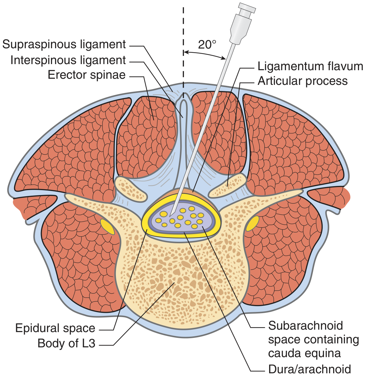
Anatomy Overview
- Skin and subcutaneous fat
- Supraspinous ligament
- Interspinous ligament
- Ligamentum flavum - first resistance ("give")
- Epidural space
- Dura mater + arachnoid mater - second resistance ("pop")
- Subarachnoid space - CSF flows here
Indications
- Diagnostic: Suspected meningitis/encephalitis, subarachnoid hemorrhage (if CT negative), Guillain-Barre syndrome, multiple sclerosis (oligoclonal bands), normal-pressure hydrocephalus, CNS syphilis, meningeal carcinomatosis, unexplained neurologic disorders
- Therapeutic: Intrathecal drug delivery (antibiotics, chemotherapy, analgesia), CSF drainage in idiopathic intracranial hypertension
- Imaging: Myelography, cisternography
Contraindications
Absolute
- Local skin infection or cellulitis over puncture site
- Signs of raised ICP with risk of herniation (see below)
- Uncorrected coagulopathy (INR >1.4, platelets <20,000)
Relative
- Papilledema (get CT first - absence of papilledema does NOT rule out raised ICP; it takes >48 hours to develop and is absent in up to 15% of adults and 50% of children with early raised ICP)
- Supratentorial mass lesion - CT must be done first; LP is dangerous if there is midline shift, loss of suprachiasmatic/basilar cisterns, or any posterior fossa mass
- Anticoagulation (see below)
- Unstable or uncooperative patient
CT Before LP - Indications (Box 206-1):
Key point: If bacterial meningitis is suspected and CT is needed first, do not delay antibiotics while waiting for CT or LP - start empiric treatment immediately. - Pfenninger & Fowler's, p.1439
Anticoagulation Considerations
| Agent | Safety / Action Required |
|---|---|
| Aspirin / NSAIDs alone | Generally safe; do not need to stop |
| Aspirin + another anticoagulant | Not recommended - avoid combination |
| Clopidogrel / ticlopidine | Stop 7-10 days before elective LP |
| UFH | Risk of SEH ~2%; stop before procedure |
| Warfarin | Stop 5 days; normalize INR before LP |
| LMWH | Discontinue; follow ASRA guidelines |
| Hemophilia | Safe after 100% factor replacement |
| Platelets <50 × 10⁹/L | Transfuse before elective LP |
| Platelets 50-100 × 10⁹/L | Generally safe with stable count |
Equipment Required
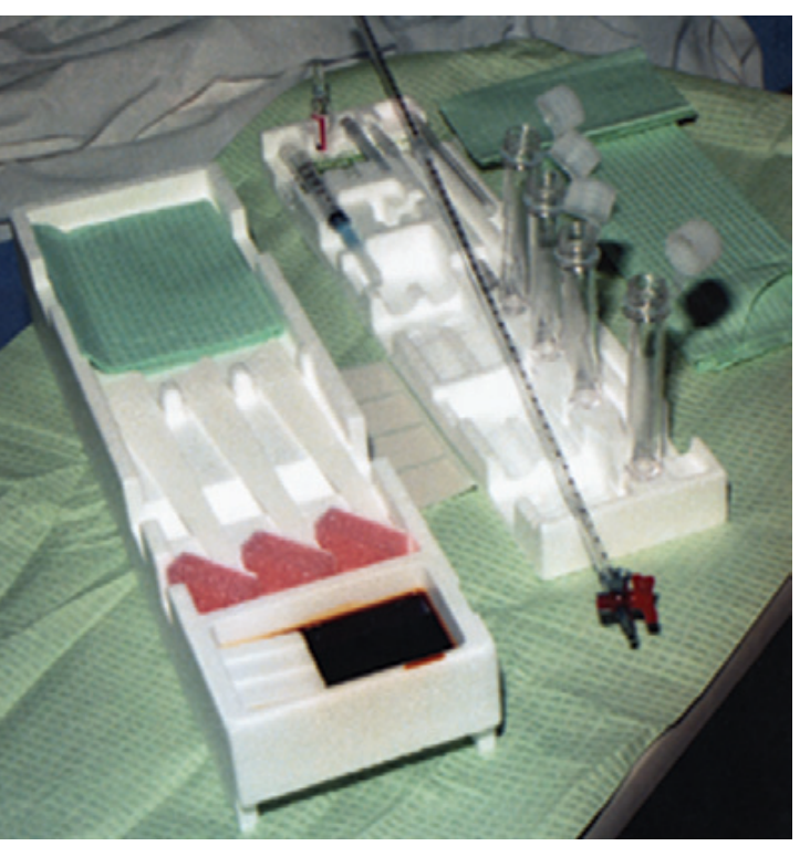
- Povidone-iodine swabs + alcohol swab
- Sterile gloves + fenestrated drape
- 20- or 22-gauge spinal needle (Quincke type with sharp bevel) + spare
- Pencil-point (atraumatic) needles (Whitacre, Sprotte) reduce post-LP headache but do not allow opening pressure measurement
- 1% lidocaine (3 mL)
- 3-mL syringe + 20-23G drawing needle
- 25-27G skin needle for local anaesthetic wheal
- Manometer + three-way stopcock (pre-assembled)
- 4 numbered, capped, sterile collection tubes
- Sterile dressing
Patient Preparation
- Explain the procedure fully - indications, expected discomfort, risks, need to remain still
- Obtain informed consent
- Fundoscopy - check for papilledema before proceeding
- Check coagulation status (INR, platelet count)
- Identify allergy to iodine or local anaesthetics
Positioning (Critical Step)
Option 1: Lateral Decubitus (Fetal Position) - Preferred for opening pressure measurement
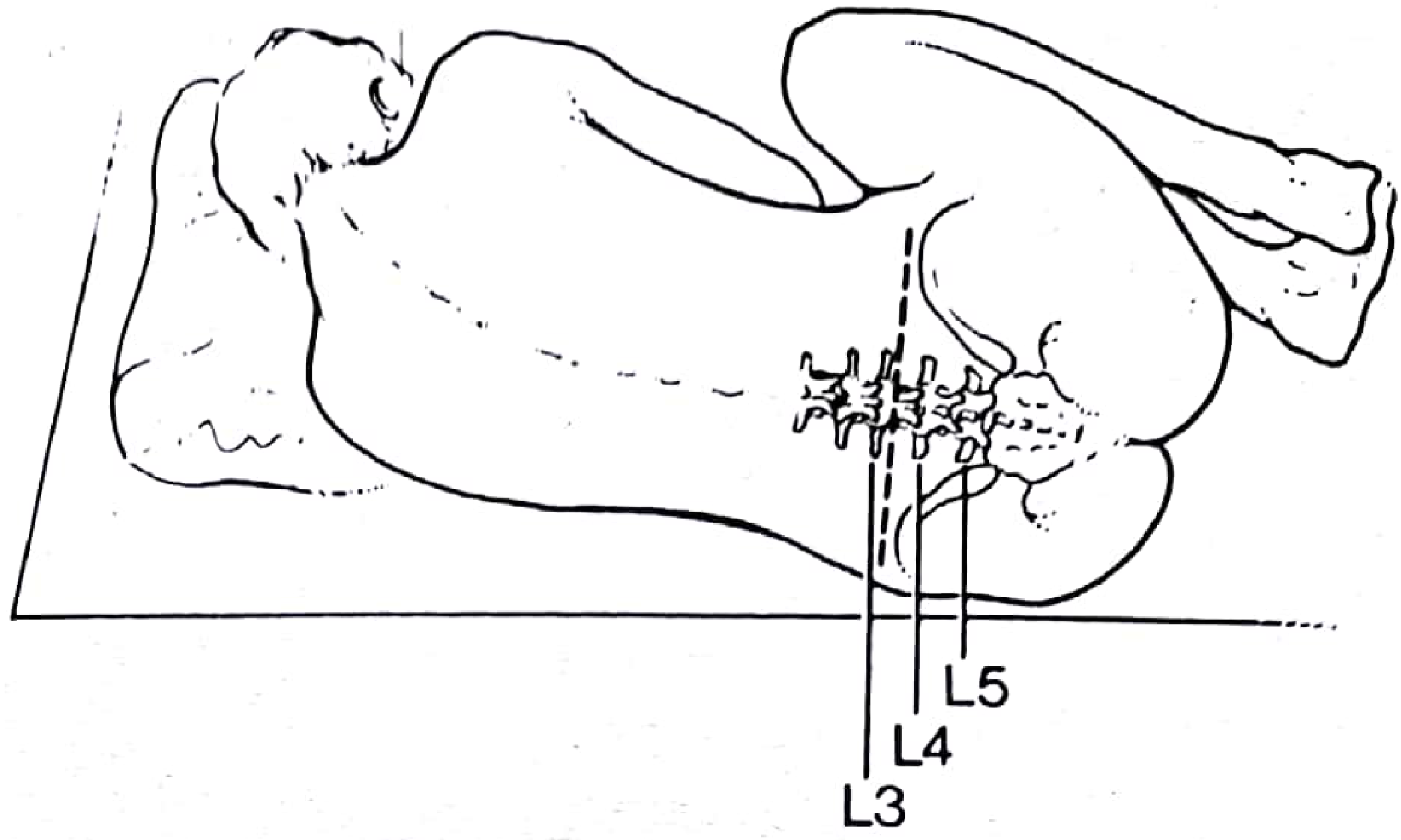
- Patient lies on LEFT side at edge of bed/table
- Neck flexed with chin toward chest
- Hips flexed toward abdomen (knees to chest - "fetal position")
- Back perpendicular to the bed surface (do not let patient roll forward/back)
- An assistant can help maintain position by placing one hand behind the neck and one behind the knees
The neck + hip flexion opens up the interspinous spaces by flattening the normal lumbar lordosis.
Option 2: Sitting (Hunched Forward) - Better for obese patients, easier to find midline
- Patient sits on edge of bed, feet on a stool
- Arms crossed over a pillow on a tray table in front
- Neck and upper back flexed - "cat-back" position
- Spine perpendicular to the floor
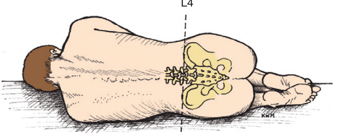
Surface Anatomy - Landmark Identification
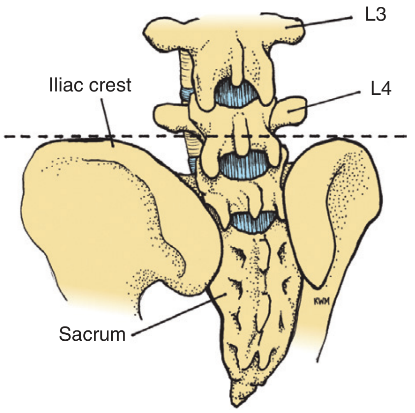
- Target interspaces: L3-L4 or L4-L5 (safest - well below cord termination at L1-L2)
- Palpate the spinous processes - feel for the gap between them
- Mark the chosen interspace with a skin indent using your fingernail or a ballpoint pen cap
Step-by-Step Procedure
Step 1 - Set Up Sterile Field
- Open the LP tray using aseptic technique
- Put on sterile gloves
- Pre-assemble the manometer: connect the two manometer pieces and attach to the vertical port of the three-way stopcock; set aside on the sterile field
- Open and stand the 4 numbered collection tubes upright in the tray slots
Step 2 - Skin Preparation
- Prep skin with povidone-iodine in expanding circles over the chosen interspace plus one space above and one below (area ≥10 cm diameter)
- Allow to dry; then place the fenestrated sterile drape over the area
Step 3 - Local Anaesthesia
- Draw 3 mL of 1% lidocaine into the syringe with the 20-23G needle
- Using the 25-27G skin needle, raise a skin wheal at the chosen interspace in the midline
- Then inject deeper into the posterior spinous region in the direction the LP needle will follow - anaesthetise supraspinous and interspinous ligaments
- For thorough anaesthesia (field block): inject midline + redirect needle laterally to both sides at the LP site, then inject small amounts above and below
Step 4 - Insert the Spinal Needle
- Hold the 20- or 22-gauge Quincke spinal needle with stylet in place
- Insert through the anaesthetised skin in the midline, between the spinous processes
- Angle ~15 degrees cephalad (toward the umbilicus), keeping strictly in the sagittal midplane
- Keep the bevel parallel to the long axis of the spine (bevel up/down in lateral position; bevel to the side in sitting) - this spreads rather than cuts the longitudinal dural fibres, reducing post-LP headache
- Subcutaneous tissue: soft resistance
- Supraspinous/interspinous ligaments: firm resistance
- Ligamentum flavum: increased resistance then "give"
- Epidural space
- Dura-arachnoid: "pop" or sudden loss of resistance - you are in
Depth varies: ~4-5 cm in an average adult, up to 8 cm in obese patients. After 3-4 cm, stop and check the hub by removing the stylet. If no fluid, replace the stylet and advance a few more mm, then check again.
Step 5 - Confirm Subarachnoid Placement
- Remove the stylet - clear CSF should drip freely from the hub
- If no fluid: rotate needle 90-180 degrees (nerve root or debris may be occluding the bevel)
- If still no fluid (dry tap): replace stylet, withdraw completely, reposition patient (try sitting if was lying, or vice versa), reattempt at a different interspace
Step 6 - Measure Opening Pressure
- Anchor the needle hub between thumb and index finger of one hand, braced against the patient's back
- Attach the manometer/stopcock assembly to the needle hub
- Ask the patient to relax and straighten the legs (flexed position artificially elevates pressure)
- Read the CSF level in the manometer
- If sitting, opening pressure cannot be reliably interpreted (gravity adds to reading)
- Record the pressure
Step 7 - Collect CSF Samples
| Tube | Volume | Send for |
|---|---|---|
| Tube 1 | 1-2 mL | Bacteriology: Gram stain, culture (bacteria, fungal, TB, viral), acid-fast stain |
| Tube 2 | 1-2 mL | Biochemistry: Glucose, protein, protein electrophoresis |
| Tube 3 | 1-2 mL | Haematology: Cell count, differential (WBC, RBC) |
| Tube 4 | 1-2 mL | Optional (guided by clinical scenario): VDRL, India ink, cryptococcal antigen, cytology, oligoclonal bands, myelin basic protein, PCR for viruses |
Collect tubes 1 and 4 for cell count if traumatic tap is suspected - RBC count decreases tube 1 to tube 4 in a traumatic tap, but stays constant in true subarachnoid haemorrhage. For every 700 RBCs: add 1 WBC and 1 mg/dL protein to correct.
Step 8 - Remove the Needle
- Replace the stylet before withdrawing the needle (reduces risk of nerve root aspiration and epidermoid tumour formation from implanted epidermal cells)
- Withdraw the needle in one smooth movement
- Apply firm pressure with gauze
- Apply a sterile dressing (Band-Aid)
Step 9 - Post-Procedure Care
- Advise the patient to lie flat after the procedure (evidence for lying prone or supine is debated, but flat positioning is widely practised)
- Keep supine for at least 2-4 hours (some guidelines recommend up to 24 hours - Pye's Surgical Handicraft)
- Encourage generous oral fluid intake
- Monitor for complications - especially headache, back pain, leg weakness, bladder/bowel dysfunction
Lateral (Paramedian) Approach
- Insert needle 1.5-2 cm lateral to midline (to the side of the spinous process)
- Direct needle ~20 degrees medially and 15 degrees cephalad
- This bypasses the supraspinous and interspinous ligaments; needle passes through paraspinal muscles and ligamentum flavum directly
Ultrasound Guidance
- Obese patients (cannot palpate spinous processes)
- Severe scoliosis
- Elderly patients with degenerative spine changes
- Previous spinal surgery
Normal CSF Values
| Parameter | Normal |
|---|---|
| Appearance | Clear, colourless ("like water") |
| Opening pressure | 7-18 cm H₂O |
| WBC | <5 cells/mm³ (all mononuclear) |
| RBC | 0 |
| Glucose | 2.5-4.5 mmol/L (60-80% of simultaneous serum glucose) |
| Protein | 15-45 mg/dL |
Complications
1. Post-Lumbar Puncture Headache (Most Common)
- Incidence: 10-25%; usually self-limiting
- 90% occur within 48 hours, may persist up to 14 days
- Characteristic: Postural - worse sitting/standing, relieved by lying flat (positional headache = pathognomonic)
- Cause: persistent CSF leak through dural puncture site → low ICP → downward traction on pain-sensitive intracranial structures
- Use smallest effective gauge needle (22G is standard compromise; 24-27G reduces headache but prevents opening pressure measurement)
- Orient bevel parallel to long axis of spine - spreads dural fibres rather than cutting them
- Replace stylet before removing needle
- Conservative: bed rest, generous hydration, analgesics (paracetamol, NSAIDs, caffeine 300 mg PO)
- Persistent/severe: Epidural blood patch (5-20 mL autologous blood injected epidurally at LP site) - highly effective
2. Traumatic / Bloody Tap
- Inadvertent puncture of spinal venous plexus
- Self-limiting in most patients
- Differentiate from true SAH: send tube 1 and tube 4 for cell count (RBC clears in traumatic tap, stays constant in SAH); also look for xanthochromia (not present in traumatic tap)
3. Brain Herniation
- Occurs when LP is performed with raised ICP + mass lesion
- Prevented by CT before LP when clinically indicated
- Signs: deteriorating consciousness, Cushing's reflex, dilating pupil
4. Spinal Epidural Haematoma (SEH)
- Rare but catastrophic
- Higher risk: traumatic LP, anticoagulated or thrombocytopenic patients
- Presents: back pain → progressive leg weakness/paralysis, bladder/bowel dysfunction
- Emergency MRI → urgent laminectomy
5. Infection
- Meningitis from procedure is theoretical (use strict aseptic technique)
- Absolute contraindication: local skin infection at LP site
6. Nerve Root Complications
- Transient paresthesias (common, usually resolve within days)
- Permanent neurological deficit (very rare)
- Nerve root aspiration (prevented by replacing stylet before withdrawing needle)
7. Epidermoid Tumour
- Long-term complication (years later)
- Due to implanted skin cells if LP performed without a stylet - especially in neonates
- Always use needle with stylet
8. Other
- Cranial nerve palsies (III, IV, VI most common - traction from low ICP) - usually transient
- Disc herniation (very rare - needle traverses entire subarachnoid space into disc)
- Intracranial subdural haematoma (rare - bridging vein tearing from CSF depletion)
- Back pain (common, usually mild and transient)
Troubleshooting: "Dry Tap"
| Problem | Solution |
|---|---|
| Needle in bone | Withdraw to skin, re-angle more cephalad |
| Needle deviated laterally | Withdraw, ensure strict midline |
| Bevel occluded by nerve root | Rotate needle 90-180° |
| Needle not advanced enough | Advance slowly in small increments, checking hub |
| Patient poorly positioned | Reposition - ensure maximum flexion |
| Wrong approach | Switch from lateral decubitus to sitting or vice versa |
| Calcified ligaments / obesity | Try lateral (paramedian) approach or ultrasound guidance |
| Low CSF pressure (dehydration) | Gentle suction with 1-mL syringe |
| Failed after 2-3 attempts | Consider interventional radiology / fluoroscopic guidance |
Summary Checklist
- Review indications and exclude absolute contraindications
- Check fundoscopy / CT if focal neurology or raised ICP suspected
- Check coagulation status; correct if needed
- Informed consent obtained
- Position patient optimally with maximum spinal flexion
- Identify L3-L4 or L4-L5 interspace using Tuffier's line
- Sterile technique: prep, drape, gloves
- Local anaesthesia: skin wheal + deeper infiltration
- Insert needle midline, 15° cephalad, bevel parallel to spine axis
- Confirm CSF flow; measure opening pressure (legs straightened)
- Collect 4 labelled tubes (~1-2 mL each)
- Replace stylet before withdrawing needle
- Apply dressing; advise post-procedure care
- Document: position, interspace, needle gauge, opening pressure, CSF appearance, tubes sent, complications