
Prepare me for my finals md anaesthesiology practical exam and viva . Thoroughly on these topics and also give me all the possible viva questions they can ask . 1. Anaesthesia machine 2. vapourisers 3. breathing systems- Bain’s, JR and Universal F 4. defibrillator 5. O2 delivery devices 6. laryngoscope 7. ET Tube 8. SGAs 1. airway 2. Spinal needle 3. Epidural needle 4. infusion pump 5. AMBU bag 6. cannula 7. syringe 8. DLT 9. TOF 10. Yolk assembly 11. PNS 12. CYLINDER.
MD Anaesthesiology Finals - Practical & Viva Preparation Guide
1. ANAESTHESIA MACHINE
Key Facts
- Gas supply - Pipeline inlet (central supply at 400 kPa/4 bar) and cylinder backup (via yoke assembly)
- Pressure regulators - Reduce cylinder pressure to pipeline pressure (~400 kPa)
- Pipeline inlet - Non-interchangeable Schraeder connectors (colour-coded: O2 = white/green, N2O = blue, Air = black/yellow)
- Pressure gauges - Indicate cylinder and pipeline pressure
- Flow control valves + Flowmeters (rotameters) - Bobbin/float rises in tapered tube; read at mid-float. Order from right to left: O2 always last (downstream) to prevent hypoxic mixture
- Hypoxic guard / Proportioning system - Link-25 (GE/Datex-Ohmeda): mechanical chain links N2O and O2 flowmeter valves, maintains minimum 25% O2. SCRC (Dräger): pneumatic system
- Vaporiser mount + back-bar - Interlock system prevents simultaneous opening of 2 vaporisers
- Fresh Gas Outlet (FGO)
- Breathing system
- Ventilator
- Scavenging system
- Pin Index Safety System (PISS) - cylinders
- Diameter Index Safety System (DISS) - pipeline
- Pressure failure alarm (O2 pressure drops below 200 kPa)
- O2 flush: delivers 100% O2 at 35-75 L/min bypassing flowmeters and vaporiser
- Fail-safe valve: shuts off N2O if O2 pressure fails
Viva Questions
- Describe the components of the anaesthesia machine in order of gas flow.
- What is the Pin Index Safety System? Give examples.
- O2: pins 2,5; N2O: pins 3,5; Air: pins 1,5; CO2: pins 1,6
- What is the Diameter Index Safety System?
- Non-interchangeable threaded connectors for pipeline connections; each gas has unique diameter
- Why is oxygen placed last/downstream on the back-bar rotameter assembly?
- To prevent a hypoxic mixture - any leak in the system upstream will affect N2O/air but not O2
- How does the Link-25 proportioning system work?
- Chain and sprocket mechanism links N2O and O2 flowmeter valves; max N2O:O2 ratio 3:1
- What is the O2 flush, and when would you use it?
- Delivers 100% O2 at 35-75 L/min directly to common gas outlet, bypassing flowmeters and vaporiser; used in emergency or to fill bellows
- What are the dangers of O2 flush?
- Barotrauma, awareness (bypasses vaporiser diluting volatile agent), rebreathing of exhaled gas in Mapleson A systems
- What safety features prevent delivery of a hypoxic gas mixture?
- Link-25/SCRC, O2 failure alarm, fail-safe valve, O2 placed downstream
- What is the Boyle's law applied to cylinder pressure?
- For O2 (non-liquefied): gauge pressure directly proportional to remaining contents. For N2O (liquefied): pressure remains constant (~52 bar at 20°C) until liquid is exhausted
- What are the checks you perform on an anaesthesia machine pre-operatively?
2. VAPORISERS
Key Facts
- Variable bypass (plenum) vaporiser - Most common; e.g., Selectatec (Ohmeda), Vapor 2000 (Dräger). Flow splits between bypass chamber and vaporising chamber (wicks + baffles). Temperature-compensating bimetallic strip adjusts splitting ratio as temperature changes.
- Dual-circuit vaporiser - Aladin cassette (GE-Datex); electronic
- Injection vaporiser - Agent injected directly into fresh gas (TEC 6 for desflurane)
- Draw-over vaporiser - In-circuit; for resource-limited settings (e.g., OMV, PAC)
- Temperature (compensated by bimetallic strip)
- Fresh gas flow rate (at very high or very low flows, output deviates from dial setting)
- Carrier gas composition (Helium/N2O affect vaporisation rate)
- Tipping/overfilling (liquid in bypass chamber = massive overdose)
- Altitude (lower barometric pressure = higher delivered %, same partial pressure)
Viva Questions
- What is a variable bypass vaporiser? Describe its working principle.
- What is the splitting ratio? How does it change with temperature?
- Why does the desflurane vaporiser (TEC 6) differ from others?
- SVP close to atmospheric; must be heated and pressurised; electrically controlled injection
- What happens if you tip a vaporiser?
- Liquid agent enters bypass chamber causing massively increased output and potential overdose
- What are the factors affecting vaporiser output?
- What is meant by "agent-specific" vaporiser?
- Splitting ratios are calibrated for a specific agent's SVP and clinical concentration range; cross-filling causes incorrect output
- What is the Selectatec/Vapor interlock system?
- What is the difference between in-circuit and out-of-circuit vaporisers?
- How does altitude affect vaporiser output?
- Lower atmospheric pressure - dial percentage reads higher BUT the partial pressure (and therefore potency) remains the same - no clinical dose change needed for potency; HOWEVER, Tec 6 for desflurane needs adjustment
- What is the SVP (saturated vapour pressure) of common agents at 20°C?
- Isoflurane: 33 kPa; Sevoflurane: 21 kPa; Desflurane: 89 kPa; Halothane: 32 kPa
3. BREATHING SYSTEMS
Key Facts - Overview
- A (Magill) - most efficient for spontaneous ventilation
- B, C - inefficient (rarely used)
- D (Bain) - most efficient for controlled ventilation
- E (Ayre's T-piece) - paediatric
- F (Jackson-Rees modification of T-piece)
3a. BAIN'S CIRCUIT (Mapleson D - coaxial version)
- Spontaneous ventilation: 200-300 mL/kg/min (or 2-3x minute volume)
- Controlled ventilation: 70-100 mL/kg/min (or 1x minute volume)
- Occlude the patient end
- Fill the outer tube with O2 by operating the O2 flush
- Open the patient end - a Venturi effect should collapse the reservoir bag if inner tube is patent
- Alternatively: occlude inner tube at machine end with a finger - no flow from O2 flush should be felt at patient end
3b. JACKSON-REES (Mapleson F - modified Ayre's T-piece)
- Spontaneous: 2-3x minute volume (typically 200-250 mL/kg/min)
- Controlled: 1000 mL + 100 mL/kg/min
3c. UNIVERSAL F CIRCUIT (Universal breathing system / Coaxial circle system variant)
Viva Questions - Breathing Systems
- Classify breathing systems. What are Mapleson classifications?
- Describe the Bain's circuit. What are the FGF requirements?
- How do you test integrity of the Bain's circuit? (Pethick's test)
- What is the Jackson-Rees modification of the T-piece and what is it used for?
- What is the FGF for the Jackson-Rees circuit in paediatrics?
- What is the Universal F circuit? How does it differ from a standard circle system?
- Why is Mapleson A most efficient for spontaneous breathing?
- During expiration, exhaled gas (rich in CO2) exits through APL valve first; fresh gas is nearest the patient during inspiration
- Why is Mapleson D most efficient for controlled ventilation?
- During controlled ventilation, fresh gas flow determines washout of CO2; D configuration positions FGF at machine end, which is most efficient
- What is the dead space of a Bain circuit?
- The inner tube from machine end to patient end acts as the fresh gas supply; dead space is only the connector
- What are the safety checks for a Bain circuit before use?
4. DEFIBRILLATOR
Key Facts
- Monophasic - Current flows in one direction; requires higher energy (360 J for VF)
- Biphasic - Current flows in both directions (positive then negative phase); more effective; standard energy 150-200 J for VF; lower myocardial damage
- VF/Pulseless VT: 200 J biphasic (or 360 J monophasic)
- Synchronized cardioversion: AF 100-200 J, Atrial flutter 50-100 J, SVT 50-100 J, VT with pulse 100-200 J
- Standard: one paddle right infraclavicular (sternal), one paddle left 5th ICS mid-axillary line (apex)
- Anteroposterior: front - left of sternum, back - left infrascapular
Viva Questions
- Difference between monophasic and biphasic defibrillator?
- What is synchronized cardioversion? When do you use it?
- Shock delivered on R wave; for AF, atrial flutter, SVT, VT with pulse
- What is the R-on-T phenomenon?
- Shock on T wave (relative refractory period) can induce VF; synchronization prevents this
- What are the energy levels for defibrillation in VF?
- Where do you place the paddles for defibrillation?
- What precautions do you take when defibrillating?
- "Stand clear", remove O2 mask, ensure no one touching patient, gel pads, no spark near combustible gases
- What is the difference between defibrillation and cardioversion?
- How does an AED work?
- What are the contraindications to cardioversion?
- Digitalis toxicity (relative), AF >48 hours without anticoagulation
- What is transthoracic impedance and what factors affect it?
- What are the pacemaker precautions during defibrillation?
- Paddles should be at least 8 cm from pacemaker/ICD; anteroposterior placement preferred
5. OXYGEN DELIVERY DEVICES
Key Facts
| Device | Flow (L/min) | FiO2 |
|---|---|---|
| Nasal prongs/cannula | 1-6 | 0.24-0.44 |
| Simple face mask | 5-10 | 0.30-0.60 |
| Partial rebreathing mask | 6-10 | 0.35-0.60 |
| Non-rebreathing mask (NRM) | 10-15 | 0.60-1.00 |
| Device | FiO2 |
|---|---|
| Venturi mask | Fixed 0.24, 0.28, 0.31, 0.35, 0.40, 0.60 |
| High-flow nasal cannula (HFNC) | Up to 1.00 |
Viva Questions
- Classify oxygen delivery devices.
- What is the difference between low-flow and high-flow oxygen systems?
- Low-flow: FiO2 depends on patient's breathing pattern. High-flow: FiO2 is fixed and predictable
- How does a Venturi mask work? What is the Venturi principle?
- What are the colour codes for Venturi masks?
- Blue 24%, White 28%, Yellow 35%, Red 40%, Green 60%
- What is the minimum flow for a simple face mask and why?
- 5 L/min to flush CO2 from mask dead space and prevent rebreathing
- Describe the non-rebreathing mask. What FiO2 does it deliver?
- What is HFNC? What are its advantages?
- What FiO2 does a nasal cannula deliver at 2 L/min?
- Approximately 0.28 (each 1 L/min adds ~0.04 to FiO2)
- In a patient with COPD, which O2 device is preferred and why?
- Venturi mask - delivers precise, controlled FiO2; prevents hypercapnia from hypoxic drive suppression
6. LARYNGOSCOPE
Key Facts
- Macintosh (curved): Tip placed in vallecula; lifts epiglottis indirectly via hyoepiglottic ligament. Most commonly used in adults. Sizes 1 (infant) to 4 (large adult). Better tongue control, more space for tube passage.
- Miller (straight): Tip goes under epiglottis and lifts it directly. Better for anterior larynx, long floppy epiglottis, paediatrics. More stimulating (superior laryngeal nerve).
- Grade 1: Full glottis visible
- Grade 2a: Posterior glottis visible
- Grade 2b: Only posterior commissure visible
- Grade 3: Only epiglottis visible
- Grade 4: Nothing visible
Viva Questions
- Describe the types of laryngoscope blades and their differences.
- Describe the Cormack-Lehane grading system.
- In which clinical situations would you choose a Miller blade over a Macintosh?
- How does a fibreoptic laryngoscope handle differ from conventional?
- What is a video laryngoscope? Name two types.
- What is the McCoy laryngoscope and when is it used?
- Hinged blade tip lifted by lever during laryngoscopy; used for difficult airway (anterior larynx, C-spine instability)
- What sizes of Macintosh blade do you stock? Which do you use for an adult?
- Sizes 0-4; size 3 for average adult, size 4 for large adult
- What is the laryngoscopy grade that indicates a difficult intubation?
- Grade 3 and 4 indicate difficult/failed intubation
- What is meant by "BURP" manoeuvre?
- Backwards, Upwards, Rightward Pressure on larynx to improve laryngoscopic view
- How do you check a laryngoscope before use?
- Check light (brightness, stability), blade lock/fitting, battery, cleanliness
7. ENDOTRACHEAL (ET) TUBE
Key Facts
- Adult male: 7.5-9.0 mm ID (typically 8.0)
- Adult female: 7.0-8.0 mm ID (typically 7.5)
- Paediatric (uncuffed): (Age/4) + 4 mm
- Paediatric (cuffed): (Age/4) + 3.5 mm
- High-volume, low-pressure (HVLP) cuff: Sealing pressure 20-30 cmH2O; reduces mucosal pressure necrosis; standard in modern ETTs
- Low-volume, high-pressure (LVHP): Older design; risk of tracheal necrosis
- Cuff pressure should be kept at 20-30 cmH2O (15-25 mmHg)
- Oral intubation: 21-23 cm at teeth for females, 23 cm for males (approximately 3x tube ID)
- Nasal intubation: add 2-3 cm
- Reinforced (armoured) ETT: Spiral wire inside; prevents kinking; used for head-neck surgery, prone position. Cannot be cut.
- RAE tube: Pre-formed curve (nasal or oral RAE); used for oral/nasal surgery
- Microlaryngoscopy tube: Small diameter (5 mm), long
- Laser-resistant tube: Lasertubus, Flexilas, Merocel
- Preformed (nasal) ETT
- Direct visualisation through vocal cords
- Capnography (gold standard): sustained CO2 waveform
- Bilateral chest rise and auscultation
- Absence of sounds over epigastrium
- CXR: tip 2-4 cm above carina (at T2-T4 level)
Viva Questions
- Describe the components of an ETT.
- What is the cuff pressure recommendation and why?
- What is Murphy's eye?
- How do you calculate ETT size in children?
- What is the difference between HVLP and LVHP cuffs?
- What is the "Z-79" or "IT" marking on an ETT?
- Implantation-tested/tissue-toxic tested; confirms material is biocompatible
- How do you confirm correct ETT placement?
- What are the complications of endotracheal intubation?
- Immediate: oesophageal intubation, bronchial intubation, dental injury, laryngospasm
- Intermediate: tube obstruction, kinking
- Long-term: subglottic stenosis, tracheomalacia
- What is an armoured (reinforced) tube? When is it used?
- What is a RAE tube? Oral vs nasal?
- Oral RAE curves downward (for oral surgery); nasal RAE curves upward (for facial/nasal surgery)
- At what depth do you check the ETT at the lip/teeth?
8. SUPRAGLOTTIC AIRWAYS (SGAs)
Key Facts
- Cuff seals around glottic opening
- No gastric access channel
- Seal pressure ~20 cmH2O
- LMA Classic (reusable, silicone), LMA Unique (disposable)
- Sizes: 1 (neonate <5 kg), 1.5 (5-10 kg), 2 (10-20 kg), 2.5 (20-30 kg), 3 (30-50 kg), 4 (50-70 kg), 5 (70-100 kg), 6 (>100 kg)
- Cuff inflation volume: size 1=4 mL, 2=10 mL, 3=20 mL, 4=30 mL, 5=40 mL
- Added gastric drain channel (allows passage of gastric tube 14-16 FG)
- Higher seal pressures (ProSeal: up to 30 cmH2O)
- Bite block
- i-gel: no inflatable cuff; thermoplastic elastomer that molds to anatomy
- Rigid, short handle; designed to allow blind or fiberoptic-guided intubation through it
- Used in difficult/failed intubation
- Can accommodate ETT up to 8.5 mm ID
- Full stomach/aspiration risk (relative - ProSeal reduces but does not eliminate)
- Pharyngeal pathology/mass
- Mouth opening <1.5 cm
- Airway pressures >20 cmH2O (first generation)
Viva Questions
- What is the LMA? Who invented it?
- What are first and second generation SGAs? Give examples.
- What is the ProSeal LMA and how does it differ from classic LMA?
- What is the i-gel? What is it made of?
- What are the size and cuff inflation volumes for LMA?
- What are the indications and contraindications for LMA?
- What is the LMA Fastrach (ILMA) and when do you use it?
- What seal pressure does the classic LMA provide? ProSeal?
- What are the disadvantages/risks of SGAs vs ETT?
- No airway protection from aspiration, limited seal pressure, cannot use in prone position (first gen)
- Can you use a LMA for laparoscopic surgery?
- ProSeal or second-generation only, with caution; high IAP limits airway seal
9. AIRWAY (ASSESSMENT & ADJUNCTS)
Key Facts
- Mallampati score (I-IV)
- Thyromental distance (<6.5 cm = difficult)
- Mouth opening (interincisor distance <4 cm)
- ULBT (Upper Lip Bite Test)
- Head and neck movement (<90° = difficult)
- LEMON rule: Look externally, Evaluate 3-3-2, Mallampati, Obstruction, Neck mobility
- Wilson risk sum score
- Oropharyngeal (Guedel) airway: Sizes (cm = flange to tip): 000, 00, 0, 1, 2, 3, 4. Size estimated by distance from incisors to angle of jaw. Inserted inverted in adults.
- Nasopharyngeal airway: Soft rubber tube; sizes 6-9 mm (ID). Length = tip of nose to tragus of ear. Contraindicated in base of skull fracture.
Viva Questions
- What is Mallampati classification? Describe classes I-IV.
- What is the LEMON rule for difficult airway prediction?
- Describe the DAS difficult airway algorithm.
- What is the thyromental distance and its significance?
- How do you size an oral airway?
- What are the contraindications to nasopharyngeal airway?
- What is a "cannot intubate, cannot oxygenate" (CICO) situation?
- Describe the technique for emergency front-of-neck access (FONA).
- What is the ULBT (Upper Lip Bite Test)?
- Class I: lower incisors bite upper lip above vermillion line; Class III: cannot bite upper lip
- What are the predictors of difficult mask ventilation?
- MOANS: Mask seal, Obesity, Age >55, No teeth, Stiff
10. SPINAL NEEDLE
Key Facts
- Cutting tip (Quincke-Babcock): Beveled sharp tip; higher rate of PDPH
- Pencil-point/atraumatic (Whitacre, Sprotte):
- Whitacre: solid tip, side-hole proximal to tip; lowest PDPH
- Sprotte: larger side-hole, easier CSF flow
- PDPH rate lowest with pencil-point needles
- 16G cutting: very high PDPH
- 22G: moderate
- 25-27G pencil-point: lowest PDPH (Gold standard: 25G Whitacre or Sprotte)
- 29G: very fine but difficult to use, fragile
Viva Questions
- Classify spinal needles. Name types with tip designs.
- What is the Quincke needle? What is its disadvantage?
- Cutting tip; higher PDPH due to parallel dural fibres being cut
- What is the Whitacre needle? Why is PDPH lower?
- Pencil-point; separates (rather than cuts) dural fibres, which reseal more completely
- Which spinal needle is preferred and why?
- What is PDPH? What are its features and management?
- Postural headache after dural puncture; treated conservatively (fluids, analgesics), caffeine; blood patch for refractory
- What is the gauge of the Tuohy needle?
- Describe the Tuohy needle. What is the Huber tip?
- How do you identify the epidural space?
- Loss of resistance (to saline or air); hanging drop technique
- What is a combined spinal-epidural technique?
- What are the complications of spinal anaesthesia?
- PDPH, hypotension, high/total spinal, urinary retention, nausea
11. EPIDURAL NEEDLE (TUOHY NEEDLE) - covered above; additional notes:
Additional Viva Questions for Epidural
- What is the test dose for epidural? What does it test for?
- How much catheter do you thread into the epidural space?
- What is the hanging drop technique?
- Negative pressure in epidural space draws up a drop of saline placed on Tuohy hub as it enters epidural space
- What are the contraindications to epidural?
- Patient refusal, infection at site, coagulopathy, raised ICP, hypovolaemia, allergy to LA
- Difference between spinal and epidural anaesthesia?
12. INFUSION PUMP
Key Facts
- Volumetric infusion pump: Delivers set volume per hour; alarm for air-in-line, occlusion, low battery, near-empty. Most common for IV fluids and drugs.
- Syringe pump: Delivers from a syringe at precise rates (mL/hr); used for concentrated drug infusions (propofol, morphine, vasopressors).
- PCA pump (Patient-Controlled Analgesia): Allows patient to self-administer boluses within programmed limits.
- TCI pump (Target-Controlled Infusion): Uses pharmacokinetic models (Marsh or Schnider for propofol; Minto for remifentanil) to achieve and maintain a target plasma or effect-site concentration.
- Marsh model (propofol): Weight-based; targets plasma concentration
- Schnider model (propofol): Uses age, weight, height, LBM; targets effect-site
- Minto model (remifentanil): Uses age, weight, LBM
Viva Questions
- What types of infusion pumps do you know?
- What is a TCI pump? Which pharmacokinetic model do you use for propofol?
- Difference between plasma-target and effect-site target in TCI?
- Plasma target: maintains set concentration in plasma; slower onset
- Effect-site target: overshoots plasma to rapidly achieve effect-site concentration; faster induction
- What is a PCA pump? What are its lockout interval and dose limits?
- What alarms are present in an infusion pump?
- What are the risks of infusion pump errors?
- 10-fold overdoses, free-flow (siphoning), air embolism
- What is TIVA and how do you calculate propofol infusion?
- What safety features are built into modern syringe pumps?
13. AMBU BAG (Self-Inflating Bag-Valve-Mask, BVM)
Key Facts
- Face mask (transparent, cushioned, multiple sizes)
- Self-inflating bag (~1500 mL adult; 500 mL paediatric, 250 mL neonatal)
- One-way patient valve (prevents rebreathing)
- Oxygen reservoir bag/tube
- O2 inlet port
- Pop-off (pressure relief) valve - set at ~45-60 cmH2O (may be bypassed during CPR)
- Without O2: ~0.21 (room air)
- With O2 at 10-15 L/min without reservoir: ~0.40-0.60
- With O2 at 15 L/min WITH reservoir: ~0.85-1.00
Viva Questions
- Describe the components of an AMBU bag.
- What FiO2 does an AMBU bag deliver with and without a reservoir?
- What is the pop-off valve and when do you bypass it?
- Safety pressure relief; bypassed during CPR in adults to deliver adequate ventilation against high chest wall resistance
- Describe the EC-clamp technique.
- What tidal volumes do you deliver with an AMBU bag?
- 6-8 mL/kg; visible chest rise; avoid hyperventilation
- What are the differences between the adult and paediatric AMBU bags?
- What is the difference between a self-inflating bag and an anaesthesia bag?
- AMBU: self-inflating, O2 reservoir, works without gas flow
- Anaesthesia bag (Mapleson): requires gas flow to inflate, provides feel of compliance
14. CANNULA (IV Cannula)
Key Facts
-
Material: PVC or PTFE/polyurethane
-
Over-the-needle design (Seldinger not needed)
-
Colour coding by gauge:
Colour Gauge Flow rate Orange 14G 250-300 mL/min Grey 16G 180-220 mL/min Green 18G 90-110 mL/min Pink 20G 60 mL/min Blue 22G 35 mL/min Yellow 24G 25 mL/min Violet/purple 26G 13 mL/min -
Flashback chamber, needle, cannula, wings, injection port.
Viva Questions
- What are the colour codes for IV cannulae and their flow rates?
- What is the largest cannula you would use in an emergency and why?
- 14G or 16G; maximum flow rate for blood transfusion
- What are the components of an IV cannula?
- What are the complications of IV cannulation?
- How do you reduce the risk of IV cannula-related phlebitis?
- Smaller gauge in smaller veins, sterile technique, change every 72-96 hours, avoid hand dorsum in prolonged use
- Why is a wider cannula not always better?
- Larger gauge causes more vein trauma, phlebitis; matched to clinical need
15. SYRINGE
Key Facts
- Luer-tip (slip) syringe
- Luer-lock syringe (locked connection - preferred for drugs/epidurals to prevent accidental disconnection)
- Catheter-tip syringe (enteral)
- Muscle relaxants: Fluorescent red
- Opioids: Blue
- Hypnotics: Yellow
- Anticholinergics: Green
- Vasopressors: Violet
- Local anaesthetics: Grey
Viva Questions
- What are the types of syringes? What is the difference between Luer slip and Luer lock?
- Why do we prefer Luer lock for epidural/neuraxial drugs?
- What are the standard colour codes for anaesthetic drug syringes?
- What sizes of syringes are typically used in an anaesthetic setup?
- What is a deadspace of a syringe?
- What precautions do you take to prevent drug errors when drawing up medications?
16. DOUBLE LUMEN TUBE (DLT)
Key Facts
- Left-sided DLT (most common): Bronchial lumen goes into left main bronchus; safer because left main bronchus is longer (5 cm) so less risk of upper lobe occlusion
- Right-sided DLT: Used when left bronchus is diseased or for left pneumonectomy; more difficult because right main bronchus is shorter (~2.5 cm) and right upper lobe bronchus may be obstructed
| Sex | Height | DLT Size (French) |
|---|---|---|
| Female | <160 cm | 35 Fr |
| Female | >160 cm | 37 Fr |
| Male | <170 cm | 39 Fr |
| Male | >170 cm | 41 Fr |
- Absolute: haemorrhage from one lung, lung abscess, bronchopleural fistula, giant bullae
- Relative: pneumonectomy, lobectomy, video-assisted thoracoscopic surgery (VATS), oesophagectomy
Viva Questions
- What is a DLT? What are its indications?
- Difference between left-sided and right-sided DLT - which do you prefer and why?
- How do you confirm correct DLT position?
- What sizes of DLT do you use for an adult male and female?
- What is one-lung ventilation? What are the physiological effects?
- Hypoxic pulmonary vasoconstriction (HPV) in the collapsed lung; V/Q mismatch; hypoxaemia is the main complication
- What is the Robertshaw DLT?
- Larger lumen, low resistance D-shaped lumens; original reusable DLT design
- What are the complications of DLT placement?
- When would you prefer a bronchial blocker over a DLT?
- How do you manage hypoxaemia during OLV?
- CPAP to operative lung, PEEP to ventilated lung, reduce tidal volume, increase FiO2, intermittent two-lung ventilation
17. TRAIN OF FOUR (TOF)
Key Facts
- All 4 twitches present with no fade and TOF ratio ≥0.9 = adequate reversal/minimal block
- 4 twitches but fade: TOF ratio 0.4-0.9 (moderate block)
- 3 twitches: ~75% receptors blocked
- 2 twitches: ~80% blocked
- 1 twitch: ~90% blocked
- 0 twitches: ~100% (profound block)
- Ulnar nerve at wrist → observe adductor pollicis (thumb adduction) - MOST RELIABLE
- Facial nerve at temporal region → orbicularis oculi
- Common peroneal nerve → dorsiflexion of foot
- TOF: 4 stimuli at 2 Hz; most common for monitoring
- Single twitch: 0.1 Hz; for deep blocks
- Tetanic stimulation: 50 or 100 Hz for 5 sec; post-tetanic count (PTC) for profound blocks
- Double-burst stimulation (DBS): 2 short tetanic bursts; detects residual block better subjectively
- Post-tetanic count (PTC): After 50 Hz tetanus, count single twitches; >8 PTC = TOF twitches will appear soon
- Adequate reversal: TOF ratio ≥0.9 (quantitative monitoring)
- Extubation safe when TOF ratio ≥0.9 by quantitative monitoring
- Neostigmine most effective when at least 2-4 twitches present (TOF count 2-4)
- Sugammadex can reverse at any level of block
Viva Questions
- What is the train of four? How do you perform it?
- What does each number of TOF twitches indicate about receptor blockade?
- What TOF ratio indicates adequate reversal for extubation?
- Where do you attach the TOF electrodes?
- What is post-tetanic count and when do you use it?
- What is double-burst stimulation?
- What is the difference between quantitative and qualitative TOF monitoring?
- When is it safe to give neostigmine?
- When at least TOF count 2 (preferably 4) or TOF ratio approaching 0.4
- Can sugammadex reverse profound block?
- Yes; 16 mg/kg for immediate reversal of rocuronium even at TOF count 0
- What is residual neuromuscular block and why is it dangerous?
- TOF ratio <0.9 postoperatively; causes pharyngeal dysfunction, aspiration, hypoxia
18. YOKE ASSEMBLY
Key Facts
- O2: 2, 5
- N2O: 3, 5
- Air: 1, 5
- CO2: 1, 6
- Cyclopropane: 3, 6
- Helium/O2: 2, 4
- O2 full cylinder: ~137 bar (full, 1500 psi in E-cylinder = ~630 L)
- N2O: ~52 bar (liquefied; pressure constant until nearly empty - only weigh to know contents)
- Air: 137 bar
Viva Questions
- What is the Pin Index Safety System? Why is it important?
- Give the pin index codes for O2, N2O, and Air.
- What is a Bodok seal? Why is it important?
- Why does the N2O cylinder pressure not decrease proportionally with use?
- N2O is stored as a liquid; pressure remains constant (~52 bar) until all liquid is vaporised
- How do you know how much N2O is remaining in a cylinder?
- Weigh the cylinder (pressure gauge is unreliable until liquid phase is exhausted)
- What is the check valve in the yoke?
- What size cylinders are attached to the anaesthesia machine?
- E-cylinders (E-size) - typically hold 660 L O2, 1800 L N2O
19. PERIPHERAL NERVE STIMULATOR (PNS)
Key Facts
- Monitoring neuromuscular blockade (intraoperatively) - TOF, PTC, DBS
- Nerve location for regional anaesthesia
- Electrodes placed over peripheral nerve (ulnar nerve most common)
- Delivers supramaximal current (typically 20-60 mA; must be supramaximal - usually 40-50 mA for ulnar)
- Supramaximal = 120-125% of the current needed to produce maximal twitch
- Square wave pulses, 0.1-0.3 ms duration
- Used to locate nerve before injection of local anaesthetic
- Insulated needle with dedicated nerve stimulator
- Current starts at 1-2 mA; reduced to <0.5 mA; appropriate motor response at ≤0.5 mA confirms proximity to nerve
- Negative electrode (black, cathode) connected to needle; positive (red, anode) is dispersive electrode on skin
Viva Questions
- What is a peripheral nerve stimulator? What are its uses in anaesthesia?
- What current do you use for supramaximal stimulation?
- Which electrode is connected to the needle in regional anaesthesia?
- Negative electrode (cathode/black) - causes hyperpolarisation and depolarisation at nerve
- What motor response confirms correct nerve localisation?
- Appropriate muscle twitch at 0.5 mA or less (0.3-0.5 mA = safe injection zone)
- What is the difference between a nerve stimulator used for NMB monitoring vs regional anaesthesia?
- What is the Rajasekaran ("seekback") sign for nerve localisation?
- Can you use a PNS to identify intravascular injection?
- No - ultrasound guidance is superior for this; PNS confirms nerve proximity
- What are the advantages of ultrasound guidance over nerve stimulator for regional blocks?
20. CYLINDER
Key Facts
| Gas | Shoulder | Body |
|---|---|---|
| Oxygen | White | Black |
| Nitrous oxide | Blue | Blue |
| Medical Air (400 kPa) | Black/White (quarters) | Grey |
| Entonox (50:50 O2/N2O) | Blue/White (quarters) | Blue |
| CO2 | Grey | Grey |
| Helium | Brown | Brown |
| Heliox (He/O2) | Brown/White | Brown |
- Size E: 680 L O2 at 137 bar; 1800 L N2O at 52 bar (on anaesthesia machine)
- Size F: theatre supply
- Size J: hospital manifold/central pipeline
- Pressure relief (bursting) disc
- Pin Index Safety System
- Thread colour + handedness (left-hand thread = flammable gas)
- Tare weight stamped on cylinder
- O2 (non-liquefied): pressure is proportional to volume
- N2O (liquefied): must weigh; pressure unreliable until liquid phase gone
- Calculate O2 in E-cylinder: Volume (L) = Pressure (bar) × 0.68 (cylinder factor for E-size)
Viva Questions
- What is the colour code for O2, N2O, Air, and Entonox cylinders?
- Why does the N2O cylinder pressure remain constant until nearly empty?
- What is Entonox? What is the Poynting effect?
- Entonox separates into O2-rich gas (top) and liquid N2O (bottom) below -6°C; can deliver hypoxic mixture; store at >10°C, invert before use
- What is the Pin Index Safety System?
- How do you calculate remaining O2 in a cylinder?
- What is the critical temperature and why is it relevant to N2O?
- Critical temp of N2O = 36.5°C; below this, N2O liquefies under pressure. N2O is stored as liquid at room temperature
- What safety features are present on cylinders?
- How often are cylinders pressure-tested?
- What is the working pressure of O2 in a pipeline vs cylinder?
- Pipeline: 400 kPa (4 bar); Cylinder: 137 bar (reduced by regulator to pipeline pressure)
- Why should cylinders not be stored near heat sources or combustible materials?
RAPID-FIRE CROSS-TOPIC VIVA QUESTIONS
- If the pipeline O2 fails in theatre, what happens to the machine and what do you do?
- Pressure alarm sounds; switch to cylinder backup; decrease fresh gas flow; consider cancelling elective surgery
- What is Boyle's law and Henry's law as applied to anaesthesia?
- Describe the path of gas from the wall pipeline to the patient's lungs.
- If a patient desaturates during OLV, walk me through your management.
- What monitors do you use to assess depth of anaesthesia AND neuromuscular block simultaneously?
- Which breathing system would you choose for a 15 kg child for a 2-hour surgery?
- Jackson-Rees or Bain's (depending on institution); consider circle system with paediatric attachments
- A patient in the ICU has a cuffed ETT with cuff pressure of 40 cmH2O. What are the risks?
- Tracheal mucosal ischaemia, tracheomalacia, tracheal stenosis; reduce to 20-30 cmH2O
- How do you choose the correct LMA size for a 70 kg patient?
- LMA size 4
- Describe the pre-use check of a defibrillator.
- What is meant by "fail-safe" and "fool-proof" in anaesthesia equipment design?
Kindly add images to each topic with labelling . And kindly give answers also to the viva questions which is not answered .
anaesthesia machine components labelled diagram flowmeters vaporiser
This medical research diagram illustrates an experimental setup for a neuromuscular Brain-Machine Interface (BMI) using a non-human primate model. The illustration depicts a seated macaque performing manual reaching and grasping tasks in a 3D workspace. Key anatomical and technological components include: 1) Cortical recording: A 4x4 platinum electrocorticography (ECoG) electrode array is shown implanted over the left primary motor cortex (M1) to capture brain activity. 2) Muscle activity: Electromyography (EMG) electrodes are placed on the right arm to record intrinsic motor signals from muscle groups. 3) Kinematic tracking: Spherical position markers are attached to the arm and hand, linked to a 3D tracking system to measure joint angles (shoulder and elbow). 4) Behavioral interface: The setup features a 'Home' button and a 'Touch sensor' with a knob to facilitate reaching, pulling, and releasing movements. The diagram outlines the data acquisition pathway where neural and muscular signals are decoded to drive external devices, such as the indicated robotic arm, for rehabilitative or assistive technology research.
This schematic diagram illustrates a self-developed internal tocodynamometry machine used for monitoring fetal head descending thrust during labor. The illustration depicts three primary components: a pressure-sensitive sensor, a connecting rod, and an external monitoring unit. The sensor is shown in direct contact with the crown of a fetal head in the cephalic position, stabilized by a clinician's hand. A linear connecting rod, featuring three reinforcement bands, transmits the physical force from the sensor to the external device. The rectangular monitoring unit contains a display screen on the left and a circular dial with a cross-quadrant interface on the right. This diagnostic setup is designed to measure intrauterine pressure and fetal descent forces at specific stages of cervical dilation (3-5 cm, 5-8 cm, and 8-10 cm). The educational focus is on the instrumentation and clinical application of internal monitoring to assess labor progression and predict the necessity for emergency obstetric interventions.
variable bypass vaporiser cross section diagram components
This anatomical diagram presents an axial cross-section of the upper lumbar spine, focusing on the organization and relationships of the posterior paraspinal musculature. The image demonstrates the components of the erector spinae group and the deeper intrinsic back muscles relative to bony landmarks such as the spinous process and vertebral body. Labels indicate the following structures: (A) Spinalis muscle, the most medial component of the erector spinae, located adjacent to the spinous process; (B) Longissimus muscle, situated laterally to the spinalis; (C) Iliocostalis muscle, representing the most lateral column of the erector spinae group; and (D) Multifidi muscles, which are positioned deep to the erector spinae and immediately lateral to the vertebral laminae and spinous process. This anatomical mapping is critical for understanding the surgical corridors used in paraspinal approaches, such as direct spinal canal decompression or pedicle screw fixation in the treatment of lumbar burst fractures. The cross-section clearly delineates the fascial planes separating these muscle groups, providing essential guidance for minimally invasive surgical retraction.
An educational anatomical and pathophysiological diagram illustrating the tissue hallmarks of acute myocarditis. The illustration includes three main components: a cross-sectional schematic of the heart ventricles, a detailed view of a blood vessel, and a simulated histopathology section. The ventricular cross-section highlights a localized inferior-lateral lesion in the left ventricle, showing subepicardial spread consistent with typical myocarditis patterns. Labels identify key pathological processes: 'Increased vasopermeability / hyperemia,' depicted by a dilated blood vessel with leaking fluid particles; 'Tissue oedema / inflammatory infiltration,' indicated by lighter coloration and texture changes in the myocardial wall; and 'Myocyte necrosis / interstitial space expansion,' illustrated in the simulated histology panel. This microscopic view shows eosinophilic cardiomyocytes with interspersed blue-stained inflammatory cells and expanded spaces between fibers. The diagram serves to correlate macroscopic Cardiac Magnetic Resonance (CMR) targets with cellular-level inflammatory mechanisms including viral-induced immunoreactive responses and vasoactive phenomena.
Bain coaxial breathing circuit diagram
This medical anatomical diagram illustrates a schematic sagittal section of the brain, focusing on the dB2 subclass axonal projections within the respiratory and vestibular circuits of the hindbrain. The diagram highlights key neuronal nuclei and their connectivity patterns. The parafacial respiratory group/retrotrapezoid nucleus (pFRG/RTN) and the lateral vestibular nucleus (LVN) are represented by purple circles. Green lines signify axonal projections originating from these dB2-derived nuclei. One projection path shows pFRG/RTN axons connecting to the pre-Bötzinger complex (preBötC), a smaller green-labeled nucleus essential for respiratory rhythm. A second major pathway demonstrates LVN axons descending posteriorly toward the spinal cord. The schematic provides essential clinical context for neurobiology, demonstrating how specific hindbrain progenitor domains differentiate into specialized nuclei that regulate autonomic functions like breathing (via preBötC) and motor reflexes (via vestibulospinal projections to the spinal cord). It serves as an educational tool for understanding brainstem neuroanatomy and functional circuit development.
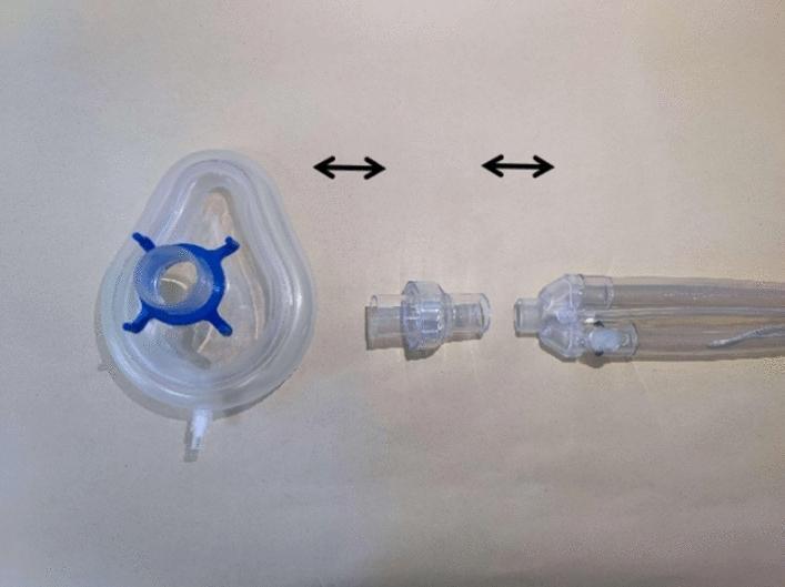
This clinical photograph serves as a schematic diagram illustrating the assembly of a non-invasive high-frequency oscillatory ventilation (NIHFOV) circuit. The image displays three primary medical device components arranged horizontally on a neutral background, with double-ended black arrows indicating the connection sequence. From left to right, the components include: 1) A clear, teardrop-shaped silicone non-invasive ventilation (NIV) mask featuring a blue four-pronged headgear attachment ring and a distal sampling port. 2) A clear, cylindrical disposable leak valve designed to facilitate the venting of exhaled CO2. 3) A proximal segment of a flexible, transparent ventilator breathing circuit showing multi-lumen tubing. The setup demonstrates the critical interface between the ventilator tubing, the mandatory leak valve for safety and gas exchange, and the patient interface (mask). This visual is intended for clinical training and educational instruction on the proper configuration of NIHFOV hardware for respiratory support.
laryngeal mask airway LMA classic supraglottic device
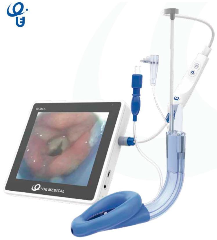
This clinical photograph displays the SaCoVLM video laryngeal mask airway (LMA) system, a specialized supraglottic airway device designed for visualization during airway management. The assembly consists of a curved, semi-transparent breathing tube terminating in a blue, inflatable anatomical mask cuff. Integrated into the device is a video stylus system connected to a handheld control unit with power and capture buttons. Multiple access ports are visible along the tube, including a central channel for gas exchange or endotracheal tube (ETT) insertion, a gastric drainage port, and ports for pressure monitoring and CPAP ventilation. The handheld unit is tethered via a blue connector to a 7-inch portable monitor. The monitor screen displays a high-definition endoscopic view of the glottis, showing the vocal cords and epiglottis, which allows for real-time visual confirmation of device placement and facilitates rescue intubation. This medical technology is utilized by anesthesiologists and emergency physicians to secure the human airway while providing direct visualization of the larynx.
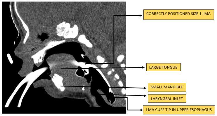
This sagittal CT scan of a neonate illustrates the placement of a size 1 laryngeal mask airway (LMA) in the context of congenital upper airway obstruction. The patient exhibits severe micrognathia, evidenced by a significantly small mandible, and macroglossia, where a large tongue occupies the majority of the oral cavity, contributing to mechanical obstruction. The LMA is seen correctly positioned with the ventilatory pathway bypassing the oral obstruction. The distal cuff is inflated within the hypopharynx, forming a perilaryngeal seal over the laryngeal inlet, while the tip of the cuff is situated in the upper esophagus. The image serves as a clinical demonstration of using a supraglottic airway device (SGAD) to maintain patency in neonatal patients with difficult anatomical airways, such as those found in Pierre Robin sequence or similar craniofacial anomalies. Key anatomical landmarks including the laryngeal inlet, tongue, and mandible are labeled to correlate the device positioning with the infant's specific pathology.
spinal needle types Quincke Whitacre Sprotte tip design comparison
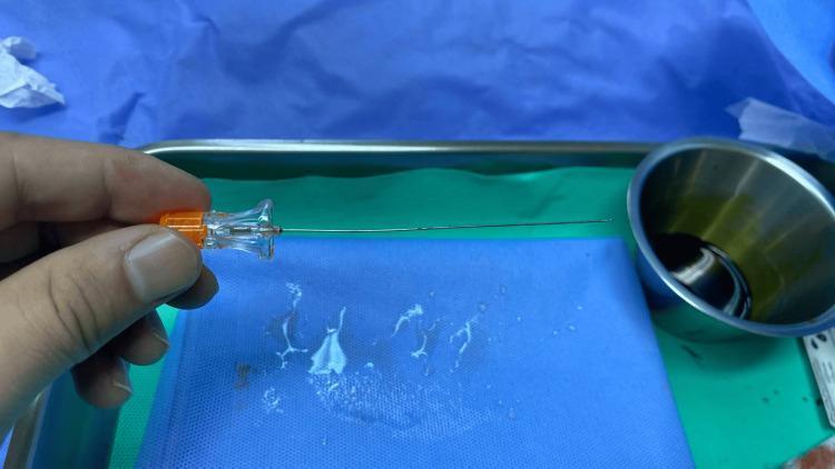
This clinical photograph displays a 22-gauge Quincke spinal needle held horizontally above a sterile surgical field. The needle features a transparent, ergonomic plastic hub with an orange-coded stylet base, consistent with standard color-coding for 22G needles. The shaft is composed of stainless steel, culminating in a sharp, beveled 'cutting' tip designed for dural penetration during neuraxial anesthesia. The background comprises an intraoperative setting, including a blue surgical drape with visible fluid droplets, a green plastic utility tray, and a stainless steel prep bowl containing an antiseptic solution, likely povidone-iodine. This image serves as an educational reference for regional anesthesia equipment, illustrating the structural components of a standard Quincke-type needle used in lumbar punctures or spinal anesthesia procedures to facilitate cerebrospinal fluid (CSF) access.
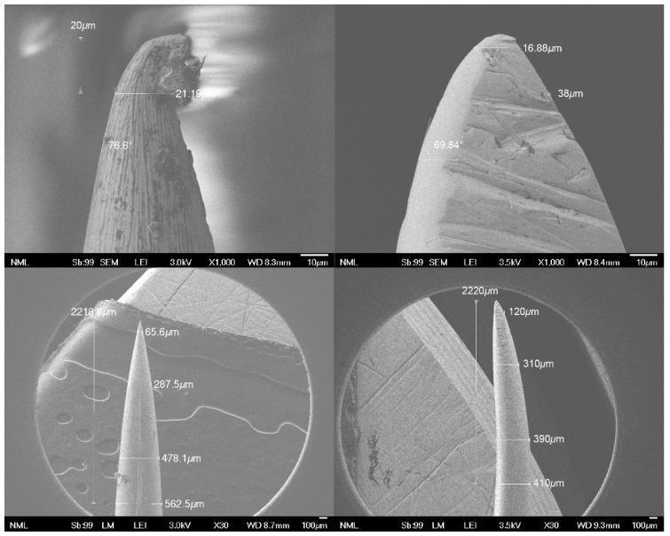
This Comparison Chart features a series of Scanning Electron Microscope (SEM) images depicting the micro-topography and geometry of two surgical needle types: a conventional commercial needle (left) and a new needle prototype (right). The top row presents high-magnification (x1000) views of the needle tips. The conventional needle displays significant surface irregularities and structural 'honing' defects at the point, whereas the prototype shows a smoother, albeit blunter, conical profile with a tip width of approximately 38 μm compared to the conventional 21.19 μm. The bottom row presents lower-magnification (x30-x35) views used for morphological assessment and dimensional measurement. These images demonstrate that the prototype needle possesses a relatively longer and more gradual tapered point, measuring 410 μm at a distance of 2220 μm from the tip, while the conventional needle measures 562.5 μm at a similar distance. This diagnostic comparison is used in medical engineering and surgery to evaluate the influence of needle design on tissue penetration resistance and the biomechanics of surgical anastomosis.
double lumen endotracheal tube DLT one lung ventilation
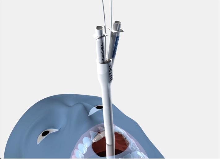
This medical illustration depicts a novel double-lumen endotracheal tube (DLT), specifically the sOLVe Tube, inserted into the oral cavity of a patient model. The device is shown in a left-sided orientation, indicated by the 'LEFT DLT' labeling on the proximal main shaft. The proximal end features a bifurcated design with two distinct ports for independent lung ventilation and access. One port is explicitly labeled 'TRACHEAL' and the other 'BRONCHIAL' (partially visible in blue), both ending in cylindrical metallic-finished connectors for anesthesia circuit attachment. Thin inflation lines for the tracheal and bronchial cuffs extend upward from the junction. The main tube body is constructed from light-colored, medical-grade silicone, designed for flexibility and to accommodate large-diameter bronchoscopes. This visual demonstrates the clinical placement of a universal DLT design intended for one-lung ventilation (OLV) and lung isolation in surgical or intensive care settings.
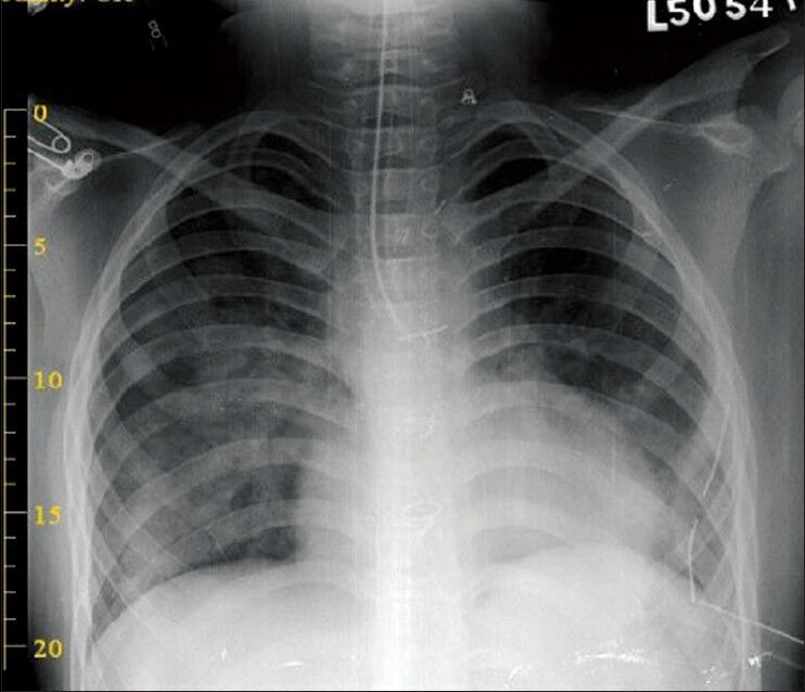
**Imaging Modality:** Anteroposterior (AP) chest radiograph (X-ray). **Anatomical Region:** Thorax, including the trachea, mainstem bronchi, and bilateral lung fields. **Observed Pathology/Findings:** - **Medical Devices:** A double-lumen endotracheal tube (DLT) is in situ. The distal tip is positioned within the left mainstem bronchus, consistent with a left-sided DLT placement for lung isolation. - **Pulmonary Parenchyma:** The right lung field demonstrates clear aeration with preserved transparency. In contrast, the left lower lung zone exhibits increased radiopacity and hazy consolidation, suggestive of atelectasis or reduced ventilation in the isolated lung. - **Mediastinum:** The cardiomediastinal silhouette appears stable; the trachea is midline. - **Pleural Space:** No overt evidence of pneumothorax or large pleural effusion is visualized. **Key Diagnostic Features:** The primary diagnostic feature is the visualization of the radiopaque markers of the double-lumen tube confirming endobronchial intubation. The differential aeration between the right and left lungs highlights the functional status of one-lung ventilation or post-procedural re-expansion. **Clinical Classification:** Post-intubation imaging; thoracic anesthesia monitoring; lung isolation verification.
train of four TOF neuromuscular monitoring peripheral nerve stimulator ulnar nerve
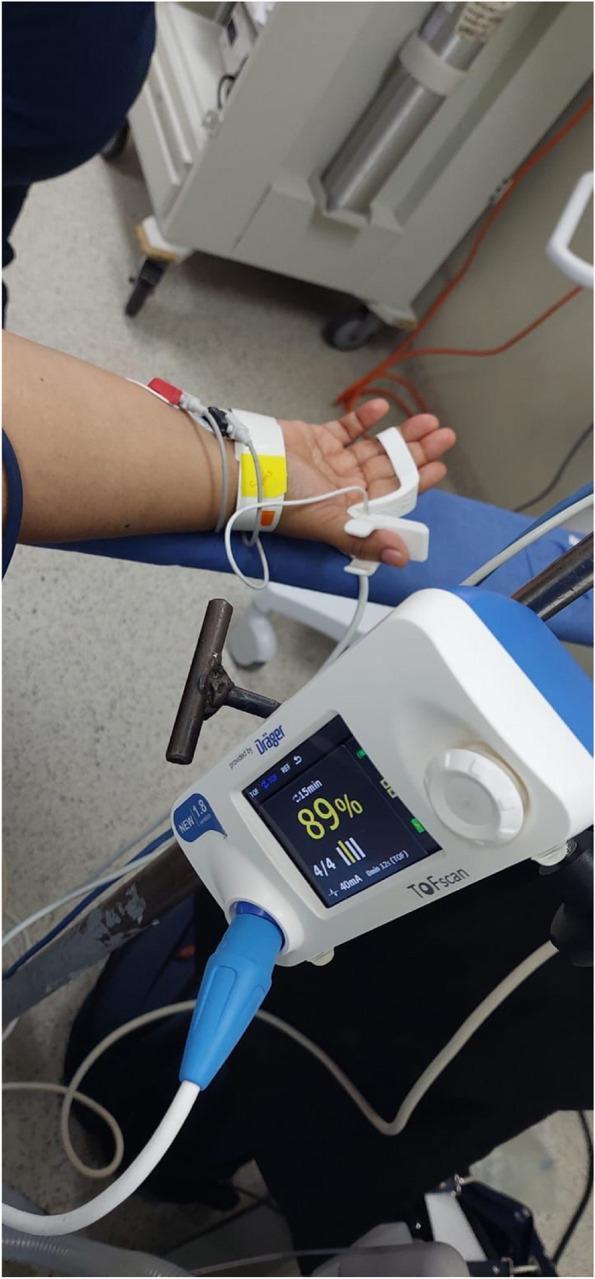
This clinical photograph illustrates the setup for Train-of-Four Ratio (TOFR) monitoring using an acceleromyographic (AMG) device in an anesthetic setting. The image shows the non-dominant hand and forearm of a patient with two peripheral nerve stimulator electrodes positioned over the ulnar nerve at the wrist and distal forearm. A white acceleromyographic sensor is attached to the second or third finger to detect muscular contractions of the adductor pollicis or flexor muscles. Adjacent to the patient, a Dräger TOFScan® monitor displays real-time neuromuscular blockade data, including a TOFR of '89%', a '4/4' twitch response indicated by four vertical bars, and a stimulation current of 40mA. This procedural image demonstrates the clinical application of quantitative neuromuscular monitoring to assess the depth of blockade and ensure safe recovery before extubation. Key educational concepts include the anatomical placement of electrodes for ulnar nerve stimulation and the interpretation of objective TOF values in anesthesiology.
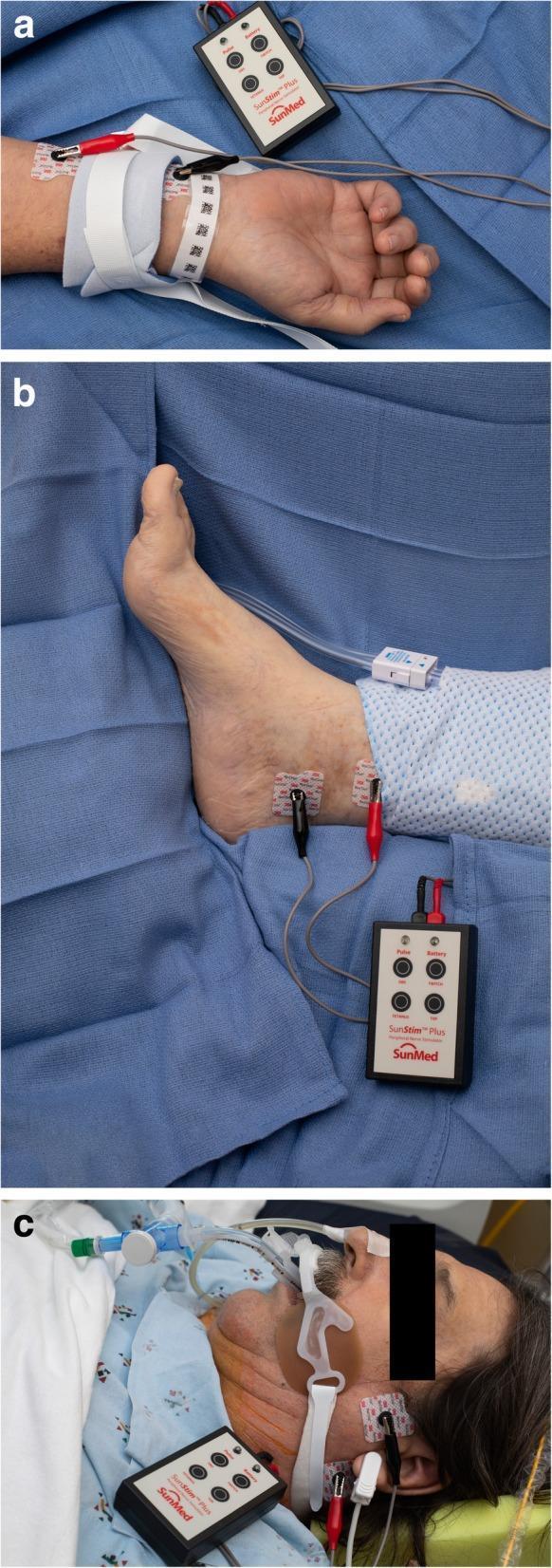
A three-panel clinical photograph demonstrating the application of a peripheral nerve stimulator (PNS) at different anatomical sites for monitoring neuromuscular blockade. Panel (a) shows the SunStim™ Plus device connected via red and black electrodes to the ulnar nerve at the wrist, notable for the presence of a white limb restraint. Panel (b) illustrates the device connected to the posterior tibial nerve at the medial malleolus of the ankle. Panel (c) shows the PNS electrodes placed over the facial nerve branches near the jawline and ear of a patient who is intubated with a secured endotracheal tube. The series highlights common sites for Train-of-Four (TOF) monitoring in an Intensive Care Unit (ICU) or perioperative setting, particularly when patient positioning or restraints limit access to the standard adductor pollicis muscle. Key educational concepts include electrode placement for nerve stimulation, the influence of monitoring site selection on the assessment of neuromuscular recovery, and the management of patients receiving neuromuscular blocking agents (NMBAs).
oxygen delivery devices nasal cannula venturi mask non-rebreathing mask comparison
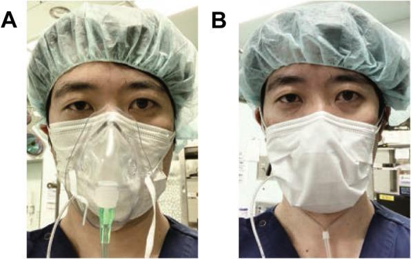
This clinical photograph displays a side-by-side comparison (Panel A and B) of two different supplemental oxygen delivery methods used in conjunction with a surgical mask, specifically discussed in the context of COVID-19 infection prevention. In both images, a healthcare provider is shown wearing a green bouffant surgical cap and a blue scrub top. Panel A demonstrates an oxygen mask applied over a white pleated surgical mask, representing a method to prevent aerosol dispersal during post-extubation. Panel B illustrates an alternative method where a nasal cannula is worn underneath a surgical mask, with the tubing exiting from the bottom of the mask. The images compare the layering of respiratory protection and oxygen delivery devices, highlighting clinical protocols aimed at maintaining oxygenation (FiO2) while providing an inhibitory barrier against respiratory droplets in a high-risk environment such as an intensive care unit (ICU) or operating room.
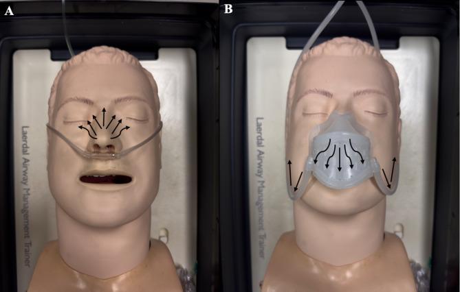
This comparison photograph illustrates a medical simulation study on oxygen flow using a supine airway management manikin. Panel A (unmasked condition) shows a nasal cannula delivery system with black arrows indicating the radial dispersion of oxygen flow upward and outward from the nares across the midface and toward the eyes. Panel B (masked condition) demonstrates a specialized oxygen scavenger mask covering the nose and mouth. Here, the black arrows indicate redirected oxygen flow downward toward the chin and peripheral venting away from the oculofacial field. The images are used to teach concepts of clinical safety, specifically the mitigation of high local oxygen concentrations near the eyes during surgical procedures to prevent fire hazards. The manikin features realistic anatomical landmarks including the nose, open mouth, and closed eyes, suitable for training in anesthesia and respiratory therapy.
defibrillator paddle placement biphasic cardioversion
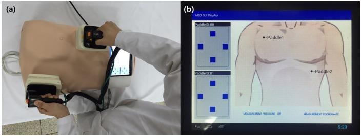
This figure presents a medical training simulator designed for defibrillation education, featuring a position-measuring system for paddle placement. Image (a) shows a physical clinical photograph of a chest manikin with two defibrillator paddles held by an operator in white clinical attire. One paddle is positioned at the upper right sternal border and the other at the cardiac apex. The paddles are wired to an integrated electronic interface. Image (b) shows the Graphical User Interface (GUI) of the position-measuring system. The digital display provides a schematic anatomical diagram of a human torso with markers indicating 'Paddle 1' and 'Paddle 2' to verify correct anatomical placement. To the left, diagnostic signal panels labeled 'PaddleID:00' and 'PaddleID:01' show spatial coordinate grids. The system is designed to provide real-time feedback to medical trainees on the accuracy of electrode positioning, a critical factor in successful cardiac resuscitation. Educational concepts include Advanced Cardiovascular Life Support (ACLS) training and the application of biomedical engineering in clinical simulation.
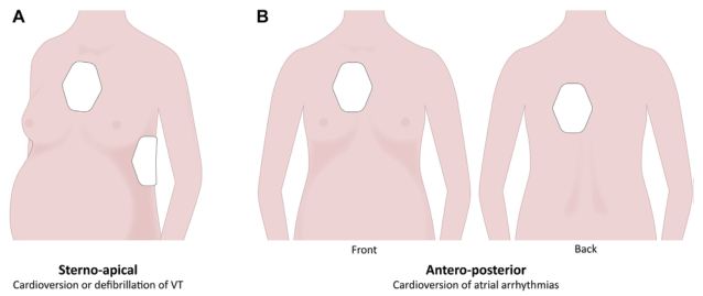
Summary : This figure illustrates the recommended pad placements for cardioversion or defibrillation in adult patients, with specific focus on sterno-apical and antero-posterior positions, and their clinical indications. illustration: # Pad Placement Methods : ## Panel A: Sterno-apical • Shows a female torso (left side) with two defibrillator/cardioversion pads. • One pad is placed on the upper right chest (sternal region). • The other pad is placed on the left lateral chest (apical region). • Labeled as "Sterno-apical". • Indication: "Cardioversion or defibrillation of VT" (ventricular tachycardia). ## Panel B: Antero-posterior • Shows a female torso from both front and back views. • One pad is placed on the anterior chest (centered over the sternum). • The other pad is placed on the back, directly behind the anterior pad (between the scapulae). • Labeled as "Antero-posterior". • Indication: "Cardioversion of atrial arrhythmias". # Clinical Indications : • Sterno-apical placement is recommended for cardioversion or defibrillation of ventricular tachycardia (VT). • Antero-posterior placement is recommended for cardioversion of atrial arrhythmias. # Design Elements : • Simple, stylized anatomical illustrations of female torsos. • Pads are depicted as white hexagons. • Each panel is clearly labeled (A and B). • Text annotations specify the clinical context for each pad placement. # Analysis : • The figure visually distinguishes between two common pad placements for electrical cardioversion/defibrillation, associating each with specific arrhythmia types. • The sterno-apical position is lateral, while the antero-posterior position is aligned front-to-back. • The use of both front and back views in panel B clarifies the spatial relationship of the antero-posterior pad placement.
AMBU bag self inflating BVM bag valve mask components
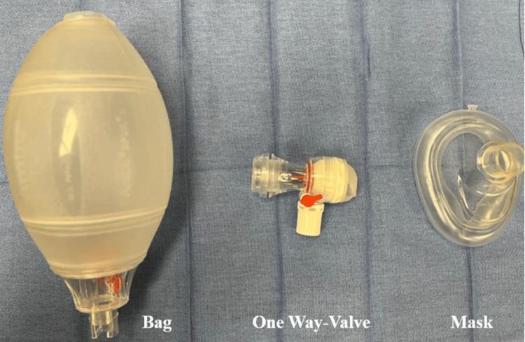
A clinical photograph displaying the disassembled components of a manual resuscitator, commonly known as an Ambu bag, used in emergency ventilation and airway management. The image is divided into three labeled sections from left to right: 'Bag', 'One-Way-Valve', and 'Mask'. The 'Bag' section shows a self-inflating, translucent, silicone-based reservoir with a pear-shaped, ridged design for grip and a connector at the distal end. The central 'One-Way-Valve' component is a non-rebreathing valve mechanism featuring a clear plastic housing with internal red and silver flow control elements and a perpendicular white oxygen inlet port. The 'Mask' section shows a clear, contoured anatomical face mask with a soft, inflatable seal designed for an airtight fit over a patient's nose and mouth. This image serves as an educational tool for identifying the equipment required for bag-valve-mask (BVM) ventilation and highlights the role of the one-way valve in directing inspiratory and expiratory gases.
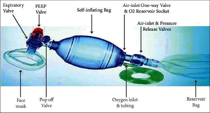
This clinical photograph and labeled diagram illustrate a standard AMBU bag (Artificial Manual Breathing Unit) system, also known as a bag-valve-mask (BVM) resuscitator, used for manual ventilation. The central component is a blue self-inflating bag, which is manually compressed to deliver tidal volume. On the proximal (patient) end, the bag connects to a clear face mask via a assembly containing a pop-off valve (pressure-limiting valve), an expiratory valve, and a PEEP (positive end-expiratory pressure) valve with a distinctive red adjustment knob. On the distal (input) end, the system includes an air-inlet one-way valve, an oxygen reservoir socket, and air-inlet and pressure release valves. Attached to this distal end is a green oxygen inlet tubing and a large, translucent green reservoir bag, which ensures high oxygen concentration delivery. The image serves as an educational guide to the pneumatic circuit and component relationships necessary for emergency airway management and basic life support.
MD Anaesthesiology Finals - Complete Viva & Practical Guide (With Images)
1. ANAESTHESIA MACHINE
Labelled Diagram
Key labelled components to know when shown a machine:
- Pipeline inlets (colour-coded Schraeder connectors)
- Cylinder yoke assemblies (with PISS pins)
- Pressure gauges
- Flowmeters/rotameters (O2 downstream/last)
- Vapourisers on selectatec back-bar with interlock
- Fresh gas outlet
- Breathing system connection
- APL valve
- Reservoir bag
- Scavenging port
Complete Viva Q&A
Pipeline inlet (or cylinder via yoke) → Pressure regulator → One-way check valves → Pipeline inlet gauges → Flowmeters (N2O, Air, then O2 last/downstream) → Proportioning system (Link-25 or SCRC) → Common gas rail → Back-bar with vaporiser → Fresh gas outlet → Breathing circuit → Patient.
Two metal pins on the yoke correspond uniquely to two holes drilled in the cylinder valve face, preventing wrong gas cylinders from being connected. Pin positions: O2 = 2,5; N2O = 3,5; Air = 1,5; CO2 = 1,6; Helium/O2 = 2,4.
Non-interchangeable threaded connectors used for pipeline connections at the wall and machine inlet. Each gas has a unique thread diameter; connectors cannot be cross-connected.
Any upstream leak in the flowmeter assembly would result in loss of O2-poor gas. Placing O2 downstream (nearest common outlet) ensures O2 is the last gas added, preventing a hypoxic mixture from reaching the patient even if upstream gases leak.
A mechanical chain links the N2O and O2 flowmeter control valve sprockets (29 teeth on O2 sprocket, 15 on N2O). If N2O flow is increased beyond the 3:1 ratio, the chain physically turns up the O2 valve. If O2 is decreased below 25%, N2O is automatically reduced. Minimum O2 flow must be 200 mL/min for N2O to flow at all.
Delivers 100% O2 at 35-75 L/min directly to the common gas outlet, bypassing flowmeters and vaporiser. Used in: hypoxic emergency; to fill the reservoir bag/bellows before starting; to flush circuits.
- Barotrauma (50+ L/min into a closed circuit can cause pneumothorax)
- Awareness - dilutes volatile agent because it bypasses vaporiser
- In Mapleson A circuits, can cause rebreathing of exhaled CO2 by pushing gas back toward patient
Link-25 or SCRC proportioning systems; O2 failure alarm (sounds when O2 supply pressure drops below threshold, typically 200 kPa); fail-safe valve (pneumatically shuts off N2O when O2 pressure fails); O2 placed downstream on flowmeter assembly.
Boyle's law: PV = constant (at fixed temperature). For O2 (stored as gas): pressure falls proportionally as gas is consumed - a half-pressure gauge means half the contents remain. For N2O (stored as liquid): pressure stays constant at ~52 bar until all liquid is consumed; gauge pressure is unreliable for estimating contents - must weigh.
Standard pre-use check (AAGBI/manufacturer checklist): Confirm O2 and pipeline supply; check cylinder pressures and cylinder back-ups; low-pressure system leak test; flowmeter function; vaporiser - level, filler cap, fitted correctly, no tipping; breathing system - leak test, CO2 absorber colour; ventilator function; APL valve function; monitors calibrated; suction working; drugs and emergency drugs prepared; scavenging connected.
2. VAPORISERS
Diagram Description (Labelled)
Variable bypass vaporiser - key labelled parts:
- Fresh gas inlet (from flowmeters)
- Concentration control dial (sets splitting ratio)
- Bypass chamber (most of fresh gas passes through here)
- Vaporising chamber (wicks + baffles increase surface area for evaporation)
- Temperature-compensating bimetallic strip (adjusts bypass:vaporiser ratio with temperature)
- Vaporiser outlet (to fresh gas outlet)
- Filling assembly with filling port (keyed, agent-specific) and drain port
- Level indicator window
Complete Viva Q&A
Incoming fresh gas splits into two streams at the concentration dial: the larger bypass stream flows directly to the outlet; the smaller stream enters the vaporising chamber (through wicks and baffles) where it becomes saturated with volatile agent. The two streams rejoin at the outlet. The concentration dial setting determines the ratio of gas diverted to the vaporising chamber.
Splitting ratio = volume of gas through bypass : volume through vaporising chamber. Example: for 2% sevoflurane, approximately 45 mL bypass : 1 mL through vaporiser at 20°C. As temperature falls, SVP drops, so vaporisation decreases - the bimetallic temperature-compensating strip responds by reducing the bypass flow, sending more gas through the vaporising chamber to maintain the set output %.
Desflurane has a SVP of ~89 kPa at 20°C (boiling point 22.8°C), near atmospheric pressure - it would spontaneously boil at room temperature. A conventional variable bypass vaporiser cannot handle this. The TEC 6 electrically heats the sump to 39°C (raising pressure to ~200 kPa above atmospheric) and uses electronic injection of desflurane vapour into the fresh gas stream under computer control. If power fails, it shuts off automatically.
Liquid agent enters the bypass chamber. This massively increases the splitting ratio in favour of vaporising-chamber output, delivering dangerously high concentrations of volatile agent to the patient. Any tipped vaporiser must be purged (30 min at high fresh gas flow with concentration dial at maximum, without connecting to patient) before use.
Temperature (compensated by bimetallic strip); fresh gas flow rate (at very high flows >15 L/min or very low flows <250 mL/min, output deviates from dial setting - high flows reduce saturation in vaporising chamber); carrier gas composition (N2O more soluble than O2 - initially decreases then increases output); altitude (lower atmospheric pressure means higher delivered volume percent, but the partial pressure and clinical effect are maintained); tipping.
Each volatile agent has a unique SVP and clinical concentration range, requiring a different splitting ratio at each dial setting. Vaporisers are calibrated for one specific agent. Cross-filling (e.g., halothane into a sevoflurane vaporiser) produces unpredictable, potentially toxic concentrations. Colour-coded, keyed filling devices (Quik-Fil, pin-indexed fill) prevent cross-filling.
A mechanical interlock system on the back-bar that physically prevents more than one vaporiser from being turned on simultaneously, preventing accidental delivery of two volatile agents at once.
Out-of-circuit (modern standard): vaporiser is outside the breathing circuit; gas passes through it once; precise, predictable output; concentration controlled by fresh gas flow. In-circuit (draw-over): vaporiser is within the breathing circuit; patient's inspiratory effort draws gas through; low resistance; used in resource-limited settings (OMV, PAC vaporiser); less predictable concentration.
At altitude, atmospheric pressure is lower, so the vaporiser outputs a higher volume percent (%) of agent for the same dial setting. However, the partial pressure of agent delivered to the patient (which determines MAC and potency) remains the same. Therefore, no dose change is needed for most agents. Exception: the TEC 6 desflurane vaporiser requires adjustment as it is a pressurised system.
Desflurane: 89 kPa; Halothane: 32 kPa; Isoflurane: 33 kPa; Sevoflurane: 21 kPa; Enflurane: 23 kPa.
3. BREATHING SYSTEMS
Mapleson Classification Summary
| System | Type | Most efficient for |
|---|---|---|
| A | Magill | Spontaneous ventilation |
| B | - | Neither (inefficient) |
| C | Waters | Neither |
| D | Bain (coaxial) | Controlled ventilation |
| E | Ayre's T-piece | Paediatric |
| F | Jackson-Rees | Paediatric (both modes) |
Bain Circuit - Labelled Features
- Outer corrugated tube (exhaled gas towards APL valve)
- Inner tube (fresh gas supply to patient end - runs inside outer tube)
- Patient connector (22 mm)
- APL valve at machine end
- Reservoir bag at machine end
- 1.8 m length
- FGF inlet at machine end
Viva Q&A - Breathing Systems
See table above. Also classified as: rebreathing (circle) vs non-rebreathing (Mapleson); open, semi-open, semi-closed, closed based on rebreathing and CO2 disposal.
Coaxial version of Mapleson D. Inner tube delivers fresh gas to patient end. Exhaled gas goes into outer corrugated tube and exits via APL valve at machine end. FGF: Spontaneous = 200-300 mL/kg/min (2-3x MV); Controlled = 70-100 mL/kg/min (1x MV).
- Occlude patient end. 2. Fill system to 30 cmH2O with O2 flush. 3. Release patient end - if inner tube is intact, Venturi effect will cause reservoir bag to deflate (collapse). 4. Alternatively: block inner tube opening at machine end with a finger - O2 flush should not fill reservoir bag if inner tube is patent (no flow would emerge from patient end).
Mapleson F = Ayre's T-piece (Mapleson E) with an open-ended reservoir bag added to the expiratory limb. No valves. Allows visual monitoring of spontaneous breathing and assisted/controlled ventilation. Used in children <25-30 kg.
Spontaneous: 2.5-3x minute volume (250 mL/kg/min). Controlled: 1000 mL + 100 mL/kg/min (Mapleson's formula). The open bag tail prevents CO2 rebreathing.
A coaxial version of the circle system. Inner tube = one limb, outer tube = return limb. Combines light weight and single-tube appearance of Bain's with efficiency of circle system (CO2 absorber, low FGF). Suitable for all patient sizes.
During expiration, alveolar exhaled gas (CO2-rich) exits first through the APL valve near the patient. Dead-space gas (CO2-free) refills the system. At the next inspiration, fresh gas is nearest the patient - CO2 is efficiently washed out with FGF equal to alveolar minute ventilation (~70 mL/kg/min).
Fresh gas enters near the machine end (opposite end to patient). During controlled ventilation, fresh gas progressively pushes exhaled gas out through the APL valve. The FGF only needs to equal the alveolar minute ventilation to prevent rebreathing (~70-100 mL/kg/min).
Dead space is minimal - only the connector (15 mm adult connector, ~2-4 mL). The inner tube delivers fresh gas right to the patient connection; there is no expiratory dead space within the circuit itself.
Perform Pethick's test; check APL valve opens and closes; check reservoir bag for leaks; check all connections are secure; ensure correct FGF rate is set; confirm correct attachment to machine FGO.
4. DEFIBRILLATOR
Image - Paddle Placement
Complete Viva Q&A
Monophasic: current flows in one direction only; requires higher energy (360 J for VF); more myocardial damage. Biphasic: current flows forward then reverses direction; more effective at lower energies (150-200 J); less myocardial injury; now the standard.
The device detects the QRS complex (R-wave sensing) and delivers the shock synchronised to the R wave, avoiding the T wave (relative refractory period). Used for: AF (100-200 J), atrial flutter (50-100 J), SVT (50-100 J), haemodynamically unstable VT with pulse (100-200 J). Not used in VF (no organised R-wave to detect - use unsynchronised defibrillation).
A shock delivered during the T-wave (relative refractory period of the cardiac cycle) can trigger VF by depolarising cells at different stages of repolarisation. Synchronization prevents this.
Biphasic: 150-200 J (manufacturer-recommended, typically 200 J for first shock). Monophasic: 360 J. Paediatric: 4 J/kg.
Standard (sterno-apical): Right infraclavicular (just below right clavicle, right of sternum) + left 5th intercostal space, mid-axillary line (apex). Antero-posterior: front pad over precordium, back pad between left scapula and spine; preferred for atrial arrhythmias.
"Clear!" - all personnel must stand clear and not touch patient or bed. Remove O2 mask from face (place >1 m away; never defibrillate near open O2 flow). No sparks near combustible anaesthetic gases. Apply gel pads or conductive gel. Check sync mode (off for VF, on for cardioversion). 15 seconds of CPR before and immediately after shock delivery (ACLS).
Defibrillation: unsynchronised, random delivery, for pulseless VF/VT - the goal is to terminate all electrical activity and allow natural pacemaker to restart. Cardioversion: synchronised to R-wave, for organised rhythms with pulse - terminates the arrhythmia without triggering VF.
AED analyses the cardiac rhythm via adhesive electrode pads; built-in algorithms detect VF or pulseless VT; charges automatically to an appropriate energy; prompts the rescuer audibly to stand clear and press the shock button (semi-automatic) or delivers the shock automatically (fully automatic). Unsuitable rhythms are not shocked.
Digitalis toxicity (risk of VF post-shock; correct digoxin level first); AF of >48 hours duration without anticoagulation (risk of thromboembolism; anticoagulate for 3+ weeks first or do TOE to exclude LAA thrombus); patient refusal; extreme electrolyte disturbances (correct first).
Typical adult TI = 70-80 ohm. Reduced by (improving shock delivery): gel pads, firm pressure on paddles, larger paddle/pad size, multiple previous shocks (reduces impedance), end-expiration (smaller lung volume). Increased by (reducing shock): large chest, hair, no gel, distance between pads.
Pads/paddles must be placed at least 8 cm from the pacemaker/ICD generator. Antero-posterior placement is preferred to divert current away from device. After defibrillation, check pacemaker threshold and function. Bifasicular ICD devices may auto-detect the shock and attempt therapy - ensure device is interrogated post-procedure.
5. OXYGEN DELIVERY DEVICES
Viva Q&A (Complete)
Low-flow (variable performance): Nasal prongs, Simple face mask, Partial rebreathing mask, Non-rebreathing mask (NRM). High-flow (fixed performance): Venturi mask, High-flow nasal cannula (HFNC/Optiflow). Specialised: CPAP mask, NIV mask, T-piece/Briggs adaptor (for intubated/tracheostomy).
Low-flow: delivered FiO2 depends on patient's tidal volume, respiratory rate, and pattern - unpredictable and varies breath-to-breath. High-flow: delivers gas at a total flow exceeding the patient's peak inspiratory flow rate, so all inspired gas comes from the device - FiO2 is precise and fixed regardless of breathing pattern.
Based on the Bernoulli/Venturi principle: a jet of O2 at high velocity through a narrow orifice (jet) creates a zone of negative pressure that entrains a fixed volume of room air through side ports. The O2:air entrainment ratio is determined by the jet orifice size and is fixed for each colour-coded valve insert, delivering a precise FiO2.
Blue = 24% (2 L/min O2); White = 28% (4 L/min); Yellow = 35% (8 L/min); Red = 40% (10 L/min); Green = 60% (15 L/min). (Memorise: Blue-White-Yellow-Red-Green = 24-28-35-40-60)
5 L/min minimum. Below this, exhaled CO2 accumulates in the mask dead space (150-250 mL), causing rebreathing and CO2 retention. The flow must flush this dead space during expiration.
Simple face mask + 600 mL reservoir bag. One-way valve between bag and mask prevents exhaled gas from entering bag; one-way flap valves on mask side ports prevent room air inhalation. Minimum 10-15 L/min to keep bag inflated. Delivers FiO2 0.60-1.00 (ideal conditions).
High-flow nasal cannula (e.g., Optiflow): delivers heated (37°C), humidified O2/air mixture at 20-60 L/min through wide-bore nasal prongs; FiO2 0.21-1.00. Advantages: exceeds peak inspiratory flow, flushing nasopharyngeal dead space; provides ~1-2 cmH2O of CPAP per 10 L/min; reduces work of breathing; patient can speak/eat; effective for type 1 respiratory failure, post-extubation, preoxygenation.
Approximately 0.28 (28%). Each additional 1 L/min increases FiO2 by approximately 0.04. Formula: FiO2 = 0.20 + (0.04 × L/min flow). Valid only up to 5-6 L/min.
Venturi mask at controlled low FiO2 (24-28%). COPD patients with chronic hypercapnia may have hypoxic drive as their respiratory stimulus. Uncontrolled O2 can suppress this drive and worsen CO2 retention. Venturi mask delivers precise, consistent FiO2 - start at 24%, titrate to SpO2 88-92%.
6. LARYNGOSCOPE
Viva Q&A (Complete)
Macintosh (curved): tip placed in vallecula; indirectly lifts epiglottis via hyoepiglottic ligament; better for adults; wider blade improves tongue control; less laryngospasm. Miller (straight): tip under epiglottis, directly lifts it; better for anterior larynx, long floppy epiglottis, neonates/infants; bulb at tip may obscure view; more likely to cause laryngospasm. McCoy: hinged tip on Macintosh blade; lever lifts epiglottis tip mechanically; reduces force needed for difficult views.
Grade 1: Full glottis visible (easy). Grade 2a: Upper half of glottis visible. Grade 2b: Only posterior commissure/arytenoids visible. Grade 3: Only epiglottis visible (no glottic structures). Grade 4: Cannot see epiglottis (failed laryngoscopy).
Anterior larynx (high larynx); long, floppy epiglottis; neonates/infants (epiglottis relatively larger and U-shaped); patients with prominent upper incisors where curved blade cannot reach vallecula; when Macintosh failed.
Fibreoptic handle: LED light source in handle; transmitted via fibreoptic bundle running through blade - gives superior, constant brightness; no bulb failure; compatible with video systems. Conventional: incandescent/halogen bulb in blade; dependent on battery contact; bulb can fail.
Standard blade (C-MAC with D-blade): Macintosh shape + camera at blade tip; image on screen; used with or without screen. Hyperangulated (GlideScope, McGrath, King Vision): extreme anterior angulation; improves grade by 1-2 C-L levels; requires special introducer/stylet to navigate tube around curve; best for anterior/difficult airways.
A modified Macintosh blade (sizes 3, 4) with a hinged tip section controlled by a lever at the handle. Activating the lever deflects the tip, which lifts the epiglottis. Reduces the force required to achieve laryngoscopic view. Used for: Cormack-Lehane grade 2-3 views; cervical spine instability (reduces atlanto-occipital extension needed); known difficult airway.
Macintosh sizes 0 (neonate), 1 (infant), 2 (child), 3 (small adult), 4 (large adult). Standard adult = size 3. Size 4 for large adult with big neck. Miller sizes 0-3.
Grade 3 (only epiglottis visible) and Grade 4 (nothing visible). Grade 2b is also associated with a high intubation difficulty score and warrants adjuncts (bougie, McCoy, video laryngoscope).
Backwards (posterior), Upwards (cephalad), Rightward Pressure applied to the thyroid cartilage by an assistant. Moves the larynx posteriorly and cephalad into the laryngoscopist's line of sight. Different from cricoid pressure (Sellick's), which compresses the oesophagus to prevent regurgitation.
- Attach blade to handle and lock (click). 2. Check light: bright, steady, white - not flickering or dim. 3. Ensure blade locks at 90°. 4. Check batteries in handle. 5. Ensure blade is clean and undamaged. 6. Have spare batteries and blade available.
7. ENDOTRACHEAL TUBE
Labelled components of an ETT:
- 15 mm standard connector (proximal)
- Tube body (PVC/polyvinyl chloride, radiopaque line)
- Cm markings from tip (confirm depth at teeth)
- Murphy's eye (side hole, distal, 2 cm from tip)
- Cuff (high-volume, low-pressure)
- Pilot balloon with one-way valve (check cuff integrity)
- Bevelled tip
Viva Q&A (Complete)
(See labelled list above.)
20-30 cmH2O (15-25 mmHg). Below 20: inadequate seal, risk of aspiration and gas leak. Above 30: mucosal capillary pressure is ~30 cmH2O; higher pressures cause mucosal ischaemia, tracheal ulceration, tracheomalacia, and long-term tracheal stenosis. Use a cuff pressure manometer (Cufflator) to check.
A side hole located 2 cm from the bevelled tip of the ETT. If the bevel occludes against the tracheal wall, carina, or enters a bronchus, Murphy's eye provides an alternative opening for gas flow, preventing complete obstruction.
Uncuffed: ID (mm) = Age/4 + 4. Cuffed: ID (mm) = Age/4 + 3.5. Alternatives: Cole formula; use child's little finger diameter as rough guide. Length of insertion (oral): (Age/2 + 12) cm.
HVLP (high-volume, low-pressure): large cuff folds against tracheal wall; contact area is wide so sealing pressure is low (~20-25 cmH2O); less mucosal ischaemia; standard in modern ETTs. LVHP (low-volume, high-pressure): older design; small, rigid cuff; high localised pressure on tracheal wall (>80 mmHg); risk of pressure necrosis and tracheal stenosis.
Z-79: American ANSI standard (now ISO 10993); IT = Implantation Tested. Confirms the tube material has passed biocompatibility testing - non-cytotoxic, non-sensitising. Every modern disposable ETT carries this marking.
- Direct visualisation through vocal cords (primary). 2. Sustained ETCO2 waveform on capnography (gold standard for confirming tracheal placement). 3. Bilateral equal chest rise and auscultation. 4. No sounds over epigastrium. 5. Fogging in tube during expiration. 6. SpO2 maintained. 7. CXR: tip at T2-T4 level, 2-4 cm above carina.
Immediate: oesophageal intubation (if unrecognised = catastrophic), right main bronchus intubation, dental injury, lip/tongue laceration, pharyngeal haematoma, laryngospasm, bronchospasm, haemodynamic response (hypertension/tachycardia). Delayed: tube obstruction (kinking, secretions), accidental extubation. Long-term: subglottic stenosis, tracheomalacia, granuloma, vocal cord palsy.
Contains a spiral wire embedded in the tube wall. Prevents kinking when flexed or compressed. Cannot be cut to shorten. Used for: head and neck surgery (tube flexed), prone position, neurosurgery (head turned), nasotracheal intubation. Downside: cannot be reinforced once kinked (does not spring back if kinked sharply); more expensive.
Pre-formed tube with a standardised curve: Oral RAE curves anteriorly (down toward chin) to keep circuit away from surgical field for oral/mandibular surgery. Nasal RAE curves posteriorly (up toward forehead) for nasal/cleft palate surgery. Fixed length - cannot adjust depth easily.
Oral ETT: 21-23 cm at teeth in women, 23 cm in men (approximately 3 × tube ID in mm). Nasal ETT: add 2-3 cm. Confirm with bilateral auscultation after each manoeuvre.
8. SUPRAGLOTTIC AIRWAYS (SGAs)
Image - Video LMA with Screen (Second Generation SGA)
Viva Q&A (Complete)
LMA = Laryngeal Mask Airway. A supraglottic airway device inserted blindly into the hypopharynx to form a seal around the laryngeal inlet. Invented by Dr. Archie Brain (British anaesthetist) in 1983, introduced clinically in 1988. Now considered one of the most important advances in airway management.
First generation: LMA Classic, LMA Unique, Ambu AuraOnce. Provide basic airway, no gastric access, seal ~20 cmH2O. Second generation: LMA ProSeal, LMA Supreme, i-gel, Air-Q. Added gastric drainage channel (allows gastric tube passage), higher seal pressures (ProSeal up to 30 cmH2O), bite block, more aspiration protection.
ProSeal has: gastric drain tube (insert 14-16 FG gastric tube); dorsal cuff (supports perilaryngeal seal); higher seal pressure (up to 30 cmH2O); bite block. Classic has none of these. ProSeal has lower risk of aspiration and can ventilate with higher airway pressures.
Made of thermoplastic elastomer (styrene ethylene butadiene styrene, SEBS). No inflatable cuff - the non-inflatable cuff molds to the perilaryngeal anatomy by body temperature and tissue pressure. Also has gastric channel, bite block, epiglottic rest. Advantages: no cuff inflation needed, quicker insertion, consistent seal.
Size 1 (neonates <5 kg): 4 mL. Size 1.5 (5-10 kg): 7 mL. Size 2 (10-20 kg): 10 mL. Size 2.5 (20-30 kg): 14 mL. Size 3 (30-50 kg): 20 mL. Size 4 (50-70 kg): 30 mL. Size 5 (70-100 kg): 40 mL. Size 6 (>100 kg): 50 mL.
Indications: elective surgical procedures with spontaneous or controlled ventilation in fasted patients; rescue airway in difficult intubation; prehospital/CPR. Contraindications: full stomach/high aspiration risk (relative - use ProSeal with caution); pharyngeal pathology; limited mouth opening (<1.5 cm); severe obesity with low respiratory compliance; known or expected high airway pressures; prone position (first generation only).
Rigid short-handled LMA (sizes 3,4,5) designed to facilitate blind or fibreoptic-guided tracheal intubation through it. Can accommodate a dedicated reinforced ETT up to 8.5 mm. Handle allows one-handed manipulation during intubation. Used in difficult airway, failed conventional intubation, in patients who cannot extend neck.
Classic LMA: ~20 cmH2O. ProSeal: 24-30 cmH2O. i-gel: 24-27 cmH2O. Higher seal pressures allow use at higher ventilatory pressures and provide more protection against regurgitation.
No protection from aspiration (especially 1st gen); limited to lower airway pressures; may displace during head turning or prone position; cannot suction the trachea; potential for laryngospasm if insufficiently deep; may cause nerve injury (lingual nerve, hypoglossal, recurrent laryngeal) with poor positioning or over-inflation.
First-generation LMA: not recommended (high IAP reduces seal integrity, increases aspiration risk). Second-generation (ProSeal, Supreme) with gastric drain: can be used cautiously in fit, non-obese patients undergoing short elective laparoscopy in Trendelenburg, with experienced anaesthetist, after confirmed high seal pressure and drainage channel patency.
9. AIRWAY (ASSESSMENT & ADJUNCTS)
Viva Q&A (Complete)
Performed with patient sitting, mouth open maximally, tongue protruded, without phonation. Class I: Entire soft palate, uvula, pillars visible (easy intubation). Class II: Soft palate, uvula visible; pillars hidden by tongue. Class III: Only soft palate visible (difficult). Class IV: Only hard palate visible (very difficult). Class III-IV predicts difficult laryngoscopy.
L - Look externally (trauma, obesity, facial hair, large tongue, small jaw, radiation burns). E - Evaluate 3-3-2 (3 finger mouth opening, 3 finger hyomental distance, 2 finger thyromental from thyroid to floor of mouth). M - Mallampati (Class III/IV). O - Obstruction (foreign body, angioedema, abscess, tumour). N - Neck mobility (<90° head extension = difficult). Each positive finding increases difficulty.
Plan A: Direct laryngoscopy; max 3+1 attempts; use bougie/external laryngeal manipulation. Plan B: Alternative intubation device (video laryngoscope, ILMA, fibreoptic). Plan C: Maintain oxygenation (SGA - LMA/ProSeal); wake patient up if elective. Plan D (CICO): Front of neck access - surgical scalpel cricothyroidotomy (scalpel-finger-bougie technique). Declare failure early; don't persist.
Distance from tip of chin (mental protuberance) to top of thyroid notch with neck fully extended. Normal >6.5 cm. <6 cm strongly predicts difficult intubation (pharyngeal axis is steep and epiglottis harder to displace).
Measure from the centre of the mouth/teeth to the angle of the jaw (or from the corner of the mouth to the tragus of the ear). Sizes by length (mm): 000 (neonate) to 4 (large adult). Adult sizes 2 (small), 3 (medium), 4 (large) used most commonly. Insert inverted 180° in adults (rotated once in posterior pharynx); insert directly in children (do NOT rotate - may push tongue back).
Suspected base of skull fracture (risk of intracranial placement through cribriform plate); coagulopathy/anticoagulation (risk of epistaxis); nasal obstruction or fracture; recent nasal surgery; adenotonsillar hypertrophy.
"Cannot Intubate, Cannot Oxygenate" (CICO) - anaesthetised patient in whom tracheal intubation has failed, SGA is unsuccessful or inadequate, and oxygenation cannot be maintained. This is a life-threatening emergency. Proceed immediately to front-of-neck access (FONA) - scalpel cricothyroidotomy.
Emergency scalpel-finger-bougie technique: 1. Palpate/locate cricothyroid membrane (between thyroid cartilage above and cricoid below). 2. Transverse stab incision through skin and membrane. 3. Finger into incision (feel trachea, hold open). 4. Bougie through incision, angled caudally. 5. Railroads a 6.0 cuffed ETT (or specific cricothyroidotomy tube). 6. Inflate cuff, ventilate, confirm ETCO2.
Patient attempts to bite upper lip with lower incisors. Class I: Lower incisors easily bite mucosa of upper lip above vermilion line (good mouth opening, neck extension). Class II: Lower incisors bite mucosa below vermillion line. Class III: Cannot bite upper lip at all. Class II-III predicts difficult laryngoscopy. Simple, reproducible, no equipment.
M - Mask seal (beard, facial trauma, edentulous). O - Obesity (BMI >26 kg/m²). A - Age >55 years. N - No teeth (loses bony support for mask). S - Stiff lungs (asthma, COPD, pulmonary fibrosis, obesity, late pregnancy). Having 2+ MOANS criteria predicts difficult BVM ventilation.
10 & 11. SPINAL AND EPIDURAL NEEDLES
Image - Quincke Spinal Needle (22G)
Viva Q&A - Spinal & Epidural (Complete)
By tip design: Cutting tip (Quincke-Babcock): bevelled, sharp, cuts dura. Pencil-point/atraumatic: Whitacre (solid pointed tip, side-hole 2 mm from tip), Sprotte (large elliptical side-hole), Gertie Marx. By gauge: 16-29G (finest = least PDPH). By use: standard spinal, introducers (19-20G), combined spinal-epidural.
Sharp bevelled cutting tip (15° to 25° bevel angle). Cuts through dural fibres. Higher PDPH rate because: (a) larger hole per gauge, (b) cutting fibres are harder to reseal. Rate ~5% with 22G Quincke.
Solid pencil-point tip with a side-hole 2 mm proximal to the tip. The tip separates (rather than cuts) dural fibres, which spring back and reseal more completely after needle removal. PDPH rate ~1-2% with 25G Whitacre. Gold standard for spinal anaesthesia.
25G or 27G Whitacre or Sprotte. Lowest PDPH rate; pencil-point tip; adequate CSF flow. 29G is technically possible but fragile and CSF flow is very slow.
Postural headache: severe, bilateral, frontal/occipital; worse sitting/standing, relieved by lying flat. Onset 12-48 hours post-dural puncture. May radiate to neck, shoulders; associated with nausea, photophobia, neck stiffness. Management: bed rest, adequate hydration (oral/IV), regular paracetamol/NSAIDs, caffeine 300 mg oral (2 cups strong coffee or IV caffeine benzoate). Definitive treatment: epidural blood patch (15-20 mL autologous blood into epidural space at same level, 90-95% success).
Standard: 16G for epidural catheter; 18G for obstetric epidural (lower catheter resistance). Length 8-10 cm.
Tuohy needle: hollow needle with curved (Huber) tip angled 15-20° to the shaft axis. The Huber tip: prevents coring of tissue; guides the catheter cephalad (in the direction of the curve) rather than allowing it to curl; allows deliberate direction of catheter. Markings every 1 cm from the tip.
Loss of Resistance (LOR) technique (most common): Tuohy needle advanced with constant gentle pressure on plunger of LOR syringe (filled with saline or air). Resistance felt in ligaments; sudden loss of resistance when tip enters epidural space. Hanging drop technique: a drop of saline is placed on the open hub of the Tuohy needle; as the needle enters the negative-pressure epidural space, the drop is drawn in. Less reliable.
Tuohy needle placed in epidural space (LOR technique). Long spinal needle (e.g., 27G Whitacre, 127 mm) inserted through Tuohy lumen until it punctures dura - CSF confirms subarachnoid position. Spinal injection made. Spinal needle removed. Epidural catheter threaded through Tuohy 3-5 cm cephalad. Advantages: rapid onset of spinal + continuous epidural for top-up/postoperative analgesia.
PDPH, hypotension (sympathetic block - give IV fluids, vasopressors), bradycardia (high block), high/total spinal (respiratory arrest, unconsciousness - intubate), urinary retention, nausea and vomiting, backache, neurological injury (rare), cauda equina syndrome (with continuous spinal or neurotoxic agents), meningitis (aseptic or bacterial).
3 mL of 2% lignocaine + adrenaline 1:200,000 (15 mcg adrenaline). Tests: Intravascular placement - HR increase ≥20 bpm within 45 sec (adrenaline response). Intrathecal placement - rapid onset of motor and sensory block within 3-5 minutes (spinal dose of lignocaine).
Thread catheter 3-5 cm into the epidural space. Less than 3 cm: risk of catheter migrating out. More than 5 cm: catheter may curl, kink, or migrate into an intervertebral foramen or vessel.
A bead of saline placed on Tuohy hub; as needle enters low-pressure epidural space, the drop is aspirated inward. Requires patient to be upright (positive intrathoracic pressure gradient needed). Less reliable than LOR, mainly used in thoracic epidurals.
Absolute: patient refusal, local infection at insertion site, coagulopathy/anticoagulation (platelet <80,000 or INR >1.5), allergy to LA. Relative: raised intracranial pressure, severe hypovolaemia/haemodynamic instability, aortic stenosis, patient unable to cooperate, previous spinal surgery, anatomical deformity.
| Feature | Spinal | Epidural |
|---|---|---|
| Needle | 22-27G Whitacre/Quincke | 16-18G Tuohy |
| Space entered | Subarachnoid | Epidural |
| Dural puncture | Yes | No |
| Onset | Rapid (5-10 min) | Slower (15-20 min) |
| Dose of LA | Small (2-3 mL) | Large (15-20 mL) |
| Level control | Limited | Controllable via catheter |
| Duration | Fixed (by agent) | Unlimited (catheter) |
| PDPH risk | Yes | No (unless accidental dural tap) |
| Hypotension | Abrupt, common | Gradual, less severe |
12. INFUSION PUMP
Viva Q&A (Complete)
Volumetric pump: large volume IV fluids; gravity-assisted roller mechanism; programmed in mL/hr. Syringe pump: precise delivery from syringe; for concentrated drug infusions; programmed in mL/hr or mcg/kg/min. PCA pump: patient-controlled; preset bolus dose, lockout interval, background infusion. TCI pump: target-controlled infusion; uses PK models to achieve and maintain set plasma or effect-site drug concentration.
Marsh model: weight-based only; targets plasma concentration; simpler; tends to overshoot at induction. Schnider model: uses weight, height, age, and calculated lean body mass (LBM); targets effect-site or plasma; more accurate in diverse populations; lower induction doses in elderly. Both use Cp-effect site equilibration constant (ke0) to model brain drug concentration.
Plasma target: pump maintains set Cp (plasma concentration); onset slower; lower peak infusion rate; preferred for maintenance. Effect-site target: pump calculates ke0 and deliberately overshoots the plasma concentration to rapidly achieve the target effect-site (brain) concentration; faster induction onset but requires higher initial infusion rates; preferred for induction. Risk of cardiovascular depression if dose not carefully adjusted.
Morphine PCA: typical bolus dose 1-2 mg; lockout 5-10 minutes; background infusion 0-1 mg/hr (controversial). Fentanyl PCA: bolus 10-25 mcg; lockout 5 min. Oxycodone: bolus 1-2 mg; lockout 5-10 min. 4-hour limit typically set (e.g., max 40-60 mg morphine/4 hr). PCA allows patient self-titration while lockout prevents overdose.
Air in line (air embolism detection); occlusion downstream (line blocked); upstream occlusion; near empty/empty; end of infusion; low battery; free-flow alarm; KVO (keep vein open - low flow alert); door open (syringe not correctly seated); programming error.
10-fold dosing errors (mg vs mcg confusion); free-flow siphoning (no anti-free-flow mechanism); wrong drug concentration programmed; wrong patient connected; air embolism; mislabelled syringes.
Total Intravenous Anaesthesia - uses propofol ± remifentanil ± ketamine by infusion (no volatile agent). Induction: propofol 1-2.5 mg/kg IV over 20-40 sec. Maintenance: propofol 4-12 mg/kg/hr (Marsh/Schnider TCI or manual infusion). BIS monitoring targets 40-60 for adequate depth. Remifentanil infusion: 0.1-0.3 mcg/kg/min. Advantages: no PONV, no air pollution, rapid recovery, preferred for TIVA with MRI, day surgery.
Anti-siphon valve (prevents free-flow under gravity); anti-free-flow mechanism on IV sets; drug library with pre-programmed soft and hard limits; dose error reduction software (DERS); audible and visual alarms; barcode scanning for drug verification; network connectivity for central monitoring; secondary confirmation for bolus delivery.
13. AMBU BAG (Self-Inflating BVM)
Image - AMBU Bag Components
Viva Q&A (Complete)
- Transparent face mask (multiple sizes, inflatable cushion rim). 2. Self-inflating bag (~1500 mL adult, 500 mL paediatric, 240 mL neonatal). 3. Non-rebreathing patient valve (one-way; during inhalation: bag to patient; during exhalation: patient to atmosphere via exhalation port). 4. Oxygen inlet port (on bag body). 5. Reservoir bag/corrugated reservoir tube (connects to O2 inlet; stores O2 between breaths to increase FiO2). 6. Air inlet valve (on opposite end of bag; allows bag to self-inflate with air when O2 not attached). 7. Optional PEEP valve, pressure manometer.
No O2: FiO2 ~0.21 (room air). With O2 at 10-15 L/min, no reservoir: FiO2 ~0.40-0.60. With O2 at 15 L/min + reservoir bag: FiO2 ~0.85-1.00.
Pop-off (pressure relief/safety) valve releases gas at ~40-45 cmH2O to protect against barotrauma. In children with compliant lungs, this is an important safety feature. In adults during CPR (stiff chest wall, reduced compliance): bypass the pop-off by covering it with a finger or using a valve-equipped device, otherwise tidal volumes may be inadequate. In cases of severe bronchospasm/ARDS, bypass may be needed to achieve ventilation.
Place mask over patient's nose and mouth. Right/dominant hand compresses bag. Non-dominant hand: Index finger and thumb form "C" shape around mask connector, pressing mask firmly down. Middle, ring, and little fingers form "E" under the mandible, providing jaw thrust to maintain airway. This two-handed seal is superior to single-hand technique.
Target 6-8 mL/kg ideal body weight (typically 500-600 mL in adults). Visible chest rise is the guide. Over-ventilation causes gastric inflation, regurgitation, and aspiration. During CPR: 500-600 mL over 1 second.
Adult: 1500 mL bag, sizes 3-5 masks, pop-off valve optional/bypassable. Paediatric: 500 mL bag, smaller masks (0-2), pop-off valve mandatory and non-bypassable (set at 35-45 cmH2O), coloured bags (blue for infant). Neonatal: 240 mL bag, pressure gauge mandatory.
Self-inflating (AMBU): re-inflates automatically due to spring mechanism; works without gas flow; delivers room air if O2 disconnected; cannot feel lung compliance; has one-way valve. Anaesthesia bag (Mapleson/reservoir): requires continuous gas flow to inflate; compressible feel allows assessment of compliance; used within breathing system; no spring - collapses without flow.
14. CANNULA
Viva Q&A (Complete)
Orange 14G: 250-300 mL/min. Grey 16G: 180-220 mL/min. Green 18G: 90-110 mL/min. Pink 20G: 60 mL/min. Blue 22G: 35 mL/min. Yellow 24G: 25 mL/min. Violet 26G: 13 mL/min.
14G (orange). Poiseuille's law: flow is proportional to r⁴ - doubling radius increases flow 16x. A 14G delivers 250-300 mL/min - essential for rapid fluid resuscitation or blood transfusion. Two 16G cannulae can approximate one 14G. Central venous catheters have smaller internal lumens than 14-16G peripheral cannulae and are NOT preferred for rapid fluid bolus.
Needle (stylet) with sharp bevel; plastic cannula body (over-needle, shorter than needle); flashback chamber (transparent - fills with blood when vessel entered); injection port (with needleless valve for drug administration); wings (for securing/gripping); safety mechanism (retractable needle in modern cannulae).
Local: haematoma, infiltration (fluid into subcutaneous tissue), extravasation (cytotoxic drug into tissue), phlebitis (pain, redness, cord along vein), thrombosis, infection (CRBSI), arterial puncture. Systemic: air embolism, catheter embolism (broken tip), septicaemia.
Use smallest gauge adequate for clinical need; avoid hand dorsum veins for prolonged use; strict aseptic technique; change cannula every 72-96 hours (or earlier if signs of phlebitis); avoid insertion near joints; use antecubital fossa/forearm for long-term; pH-neutral flush solutions; avoid hyperosmolar/vesicant drugs through peripheral cannulae.
Larger gauge = more vein wall trauma, higher incidence of phlebitis (Grade III-IV), more painful insertion. Match gauge to purpose: 22G for most drugs, 20G for most IV fluids, 18G for blood transfusion, 16-14G for major haemorrhage. Using 14G in a fine hand vein destroys the vein.
15. SYRINGE
Viva Q&A (Complete)
Luer slip: friction-fit connection between syringe tip and needle/connector; can accidentally disconnect under pressure or vibration. Luer lock: threaded collar around syringe tip that screws onto matching lock on needle hub; secure, leak-proof connection. Luer lock preferred for: epidural/intrathecal injections (accidental disconnection risks air entry), arterial lines, drug infusions under pressure.
Accidental disconnection of epidural catheter connector could allow air entry into the epidural space (spinal cord compression) or loss of drug. The locked connection provides a secure, tamper-resistant interface. Some systems use coloured non-luer (NRFit) connectors specifically for neuraxial to prevent wrong-route injections.
Muscle relaxants: Fluorescent red/orange. Opioids: Blue. Hypnotics/induction agents: Yellow. Anticholinergics: Green. Vasopressors/vasoconstrictors: Violet/purple. Anticholinesterases: Orange-red. Local anaesthetics: Grey. Tranquillisers: Salmon pink. Note: Institution-specific variations exist; always read the label.
1 mL (insulin: 1 unit = 0.01 mL markings), 2 mL (drug dilutions), 5 mL (most drug injections), 10 mL (IV drugs, flush), 20 mL (fluid bolus, drug dilution), 50 mL (TCI propofol, infusion).
The volume of drug trapped in the hub and needle after the plunger is fully depressed. In a standard 2 mL syringe with 23G needle, dead space ≈ 0.07-0.10 mL. Clinically significant for concentrated drugs (morphine, adrenaline) and in neonatal dosing. Use 3-way taps, needle-free connections, or flush to reduce drug loss.
Follow the "5 Rights" (right drug, dose, route, time, patient). Label every syringe immediately on drawing up (drug name, concentration, date, time, initials). Use colour-coded syringe labels (drug class). Never use unlabelled syringes. Prepare drugs in a quiet, distraction-free environment. Independent double-check for high-risk drugs (potassium, insulin, opioids, concentrated electrolytes). Standardise drug concentrations. Use pre-filled syringes when possible.
16. DOUBLE LUMEN TUBE (DLT)
Image - DLT Cross-Section Sizes
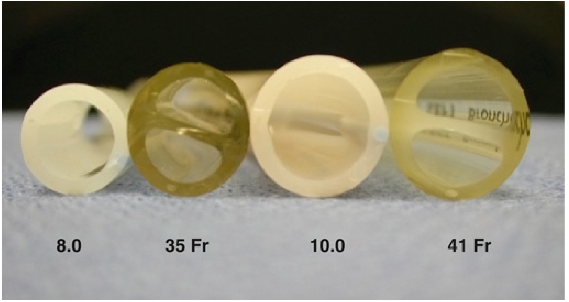
Image - DLT in situ (Oral)
Viva Q&A (Complete)
A large-bore double-lumen tube with two separate channels - a tracheal lumen (opens above carina) and a bronchial lumen (enters one main bronchus). Allows independent ventilation of each lung. Absolute indications: isolation to prevent contamination (abscess, haemorrhage from one lung, bronchopleural fistula, broncho-cutaneous fistula, giant bullae). Relative: surgical access for pneumonectomy, lobectomy, VATS, oesophagectomy, thoracic aortic surgery, thoracoscopy.
Left-sided DLT preferred in ~95% of cases. Left main bronchus is ~5 cm long (vs ~2 cm for right), giving a wide safety margin for bronchial cuff positioning without obstructing the left upper lobe bronchus. Right DLT has a slot in the bronchial cuff for right upper lobe bronchus (Murphy's eye equivalent), but its position is critical and malposition occludes the RUL easily. Use right DLT for: left pneumonectomy, left main bronchus tumour/stenosis/trauma, surgery near left carina.
- Auscultation sequence: After bilateral ventilation, clamp tracheal lumen - only left lung should ventilate; then clamp bronchial lumen - only right lung should ventilate. 2. Fibreoptic bronchoscopy (gold standard): Through tracheal lumen: should see carina clearly + blue bronchial cuff just below carina in left main bronchus. Through bronchial lumen: should see left upper and lower lobe bronchi.
Female <160 cm = 35 Fr; female >160 cm = 37 Fr; male <170 cm = 39 Fr; male >170 cm = 41 Fr. (See Miller's Anesthesia table, confirmed from textbook.)
HPV (hypoxic pulmonary vasoconstriction) occurs in the collapsed/non-ventilated lung, diverting blood to ventilated lung. However, complete HPV takes 20-30 min; shunt through collapsed lung causes V/Q mismatch and hypoxaemia. Main complication = hypoxaemia (SpO2 <90%). Also: increased airway pressure in ventilated lung, risk of atelectasis, CO2 retention.
Original reusable double-lumen tube design with large D-shaped lumens (low resistance). Made of red rubber (now PVC disposable versions). Available in left and right, sizes small/medium/large. Less commonly used now as disposable tubes have improved.
Malposition (most common - detected by routine FOB check); tracheobronchial laceration (right DLT or oversized tube most dangerous; presents as subcutaneous emphysema, pneumothorax, haemoptysis); hypoxaemia during OLV; voice changes; sore throat (large tube size); bronchial rupture.
Bronchial blocker (e.g., Arndt, Cohen, EZ-Blocker): placed through or alongside standard ETT; suitable for existing tracheostomy, difficult airway (smaller outer diameter), paediatrics; slower lung collapse; lumen too small for suctioning. DLT: rapid lung isolation, easier suctioning, can switch ventilation quickly; requires larger mouth opening and specific sizes.
- Increase FiO2 to 1.0. 2. Apply CPAP (5-10 cmH2O) to the operative (collapsed) lung - recruits alveoli, reduces shunt. 3. Apply PEEP (5 cmH2O) to the ventilated lung - improves FRC. 4. Reduce tidal volume / accept permissive hypercapnia. 5. Intermittent two-lung ventilation. 6. Surgical ligation of pulmonary artery to operative lung (eliminates shunt). 7. Discuss with surgeon about restoring two-lung ventilation. 8. Check DLT position (bronchoscopy).
17. TRAIN OF FOUR (TOF)
Image - TOF Monitor in Use (Dräger TOFscan)
Viva Q&A (Complete)
Attach two surface electrodes over the ulnar nerve at wrist (negative/cathode electrode distally, ~3 cm apart). Apply 40-50 mA supramaximal current in a pattern of 4 stimuli at 2 Hz (every 0.5 sec). Observe thumb adduction (adductor pollicis) response. Count twitches (T1-T4) and assess for fade (T4/T1 = TOF ratio).
4 twitches + no fade: <75% receptors blocked (TOF ratio ≥0.7). 4 twitches + fade: 70-80% blocked. 3 twitches: ~75-80% blocked. 2 twitches: ~80-85% blocked. 1 twitch: ~90% blocked. 0 twitches: >95% blocked (profound block). PTC used when no twitches.
TOF ratio ≥0.9 (90%) by quantitative monitoring (AMG). Subjective detection of fade by eye/touch becomes unreliable below TOF ratio 0.4. Clinical signs (head lift 5 sec, grip strength) are insufficient surrogates. Quantitative monitoring is now the standard of care.
Ulnar nerve at wrist: preferred (most reliable, adductor pollicis is purely innervated by ulnar). Alternative sites: facial nerve (orbicularis oculi or corrugator supercilii - more resistant to block, useful for intubation timing), posterior tibial nerve (plantar flexion of big toe), common peroneal nerve.
When all 4 TOF twitches are absent (profound block): apply 5 sec of 50 Hz tetanic stimulation (wait 3 sec), then single twitches at 1 Hz; count responses. PTC 1-5: deep block (TOF twitches will return in 20-40 min). PTC >12: TOF twitches expected within 10 min. PTC 0: intense block (consider sugammadex reversal vs wait).
Two short bursts of 50 Hz tetanic stimulation (3 impulses each), separated by 750 ms. Compares the strength of the two bursts (DBS3,3). Easier to detect fade subjectively than TOF; detects residual block more reliably by hand than TOF ratio. Used when quantitative monitors unavailable.
Qualitative (subjective PNS): visual or tactile assessment of twitch height; unreliable for ratios <0.4; cannot distinguish 0.7 from 0.9. Quantitative: AMG (acceleromyometry), EMG, kinemyography - gives numerical TOF ratio; can detect residual block (ratio 0.7-0.89) missed by clinical assessment; recommended by all major guidelines.
At TOF count ≥2 (preferably 4 twitches with visible fade) or TOF ratio ≥0.2. Neostigmine is most effective at minimal block (TOF ratio 0.4-0.9). Giving neostigmine during deep block (TOF count 0-1) is ineffective and may cause prolonged weakness (cholinergic crisis symptoms). Sugammadex can be used at any depth.
Yes. Sugammadex (cyclodextrin) encapsulates rocuronium/vecuronium (not succinylcholine, atracurium, cisatracurium). Dosing: Routine reversal (TOF count 2): 2 mg/kg. Immediate reversal after intubation dose: 16 mg/kg. Moderate block reversal (TOF count 1-2): 4 mg/kg. Works within 2-3 minutes regardless of depth.
TOF ratio <0.9 postoperatively. Causes: pharyngeal dysfunction and impaired swallowing (aspiration risk), upper airway obstruction, impaired hypoxic ventilatory response (cannot mount hypoxic drive appropriately), inability to cough, respiratory failure. Incidence up to 30-40% without quantitative monitoring. Leading cause of critical respiratory events in PACU.
18. YOKE ASSEMBLY
Labelled Yoke Assembly Components:
- Yoke body (attached to anaesthesia machine frame)
- Retaining screw (tightens to hold cylinder valve against yoke)
- Two index pins (PISS - unique position per gas)
- Filter washer (Bodok seal - neoprene resilient washer behind valve face)
- Gas inlet port (leads to check valve)
- Check valve/non-return valve (in yoke port - prevents back-flow)
- Pressure gauge connection
Viva Q&A (Complete)
Prevents wrong gas cylinders from being connected to a machine yoke. Two metallic pins on yoke face correspond exactly to two drilled holes on the specific cylinder valve. The combination is unique to each gas. A cylinder with wrong pin holes physically cannot be attached. Without PISS, an N2O cylinder could be connected to the O2 yoke, causing hypoxia and death.
O2 = positions 2,5. N2O = positions 3,5. Air = positions 1,5.
A resilient neoprene (rubber) washer placed between the cylinder valve face and the yoke. It deforms slightly to create a gas-tight seal when the retaining screw is tightened. It must be replaced each time a cylinder is changed - reuse can cause gas leaks. Loss of Bodok seal causes audible hissing at the yoke.
N2O is stored as a liquid-gas mixture (liquefied under pressure). At room temperature, N2O pressure = ~52 bar (critical temperature 36.5°C). As gas is used from the cylinder, liquid evaporates to maintain the pressure - so the pressure gauge reads ~52 bar until all liquid is consumed (~90% of contents have been used). Only in the final ~10% of contents does the pressure drop. Therefore: pressure gauge is useless for estimating N2O contents during the liquid phase.
Weigh the cylinder (tare weight is stamped on the cylinder neck). Subtract tare weight from current weight = weight of N2O remaining. 1 litre of N2O liquid = 1.87 kg. Example: if tare = 5 kg, current weight = 6.5 kg, then 1.5 kg of liquid N2O remains = approximately 800 L of gas.
A non-return/check valve is present in each yoke port on the machine. Function: prevents gas from flowing back from the machine into the cylinder when the cylinder is removed. Also prevents gas from a high-pressure cylinder cross-flowing into a lower-pressure second cylinder in a double-yoke assembly.
E-cylinders (size E): O2 = 660-680 L at 137 bar; N2O = 1800 L at 52 bar; Air = 680 L at 137 bar. These are backup supplies only - the machine should normally run from central pipeline. F and J cylinders are used in wards/transport.
19. PERIPHERAL NERVE STIMULATOR (PNS)
Image - PNS at Multiple Sites
Labelled PNS Controls:
- Current output dial (mA) - adjustable 0-80 mA
- Mode/frequency selector (0.1 Hz single twitch, 1 Hz, 2 Hz TOF, 50 Hz tetanus, PTC mode)
- Polarity indicator (black = negative = cathode → to needle; red = positive = anode → skin)
- Battery/charge indicator
- Stimulation rate display
Viva Q&A (Complete)
A device that delivers calibrated electrical stimuli to peripheral nerves. Uses: (1) Monitoring depth of neuromuscular blockade (NMB) - TOF, PTC, DBS, single twitch patterns. (2) Nerve location for regional anaesthesia blocks (electrical nerve locator/peripheral nerve stimulator for PNB).
For NMB monitoring: 40-60 mA is typically supramaximal for ulnar nerve (120-125% of current producing maximal twitch). Supramaximal = ensures all muscle fibres in the innervated muscle are stimulated - provides a stable, reproducible baseline. Pulse width: 0.1-0.3 ms square wave.
Negative electrode (black lead, cathode) is connected to the insulated nerve-block needle. Cathode causes depolarisation of nerve membrane at lower threshold current (less cathodal than anodal stimulation). Positive electrode (red lead, anode) is attached to skin as the dispersive electrode.
Appropriate muscle twitch at ≤0.5 mA (0.3-0.5 mA is optimal). At this current, the needle tip is within ~1-3 mm of the nerve. Twitches at 0.5-1 mA: adequate proximity but not ideal. Twitches still present at <0.2 mA: needle may be intraneural - withdraw slightly (risk of intraneural injection). Always reduce current to minimum needed for twitch before injecting.
For NMB monitoring: uses surface electrodes on skin over nerve; current 40-60 mA; measures response of muscle group; qualitative (visual/tactile). For regional nerve block: uses dedicated insulated needle as the electrode; current starts 1-2 mA, reduced to 0.3-0.5 mA; current much lower because tip is within millimetres of the nerve; response guides needle position.
When a nerve stimulator current is increased from a subthreshold level, the threshold current at which a twitch first appears is termed the minimum stimulating threshold. If the threshold is <0.2 mA, intraneural placement is suspected. The "seekback" or "Rajasekaran" approach involves slight withdrawal to restore threshold to 0.3-0.5 mA.
No. A PNS cannot detect intravascular needle placement. Only symptoms (patient reports dysgeusia/metallic taste, palpitations), direct aspiration (blood in syringe), ECG changes (with adrenaline test dose), or ultrasound visualisation can detect intravascular injection.
Ultrasound advantages: real-time visualisation of needle, nerve, adjacent vessels and spread of local anaesthetic; reduced volumes of LA needed; lower rate of intraneural and intravascular injection; faster onset; success in patients with anatomical variants. Nerve stimulator: useful when US view is poor (deep blocks, obese patients); combined US + NS is the gold standard for most major nerve blocks.
20. CYLINDER
Labelled cylinder features to know:
- Valve block (top) - with Pin Index holes
- Shoulder (colour coded by gas)
- Body (colour coded separately)
- Tare weight and serial number (stamped on neck)
- Test date (hydraulic test date stamped on collar)
- Pressure relief disc (burst disc - bursts if pressure exceeds safe limit)
- Cylinder label (contents, purity, volume, hazard symbols)
Viva Q&A (Complete)
O2: White shoulder, Black body. N2O: Blue shoulder, Blue body. Medical Air (400 kPa): Black + White quartered shoulder, Grey body. Entonox (50:50 O2/N2O): Blue + White quartered shoulder, Blue body. CO2: Grey shoulder, Grey body. (UK ISO 32/EN 1089-3 system.)
N2O is stored as a liquefied gas. At 20°C, the equilibrium vapour pressure of liquid N2O is ~52 bar. As gas is drawn off, more liquid evaporates to maintain the equilibrium pressure - so the gauge reads ~52 bar throughout the liquid phase. Only when the last of the liquid has vaporised (approximately the final 10% of contents) does the pressure begin to fall. This is similar to a partially full aerosol can.
Entonox = 50% O2 + 50% N2O premixed gas. Used for analgesia (labour, burns dressings, trauma). Poynting effect: In a cylinder at room temperature, O2 is dissolved in liquid N2O (gases dissolve in liquid above their normal solubility - a pressure-dependent dissolution effect). Below -6°C (pseudocritical temperature of Entonox), the mixture separates into N2O-rich liquid (sinks) and O2-rich gas (rises). Drawing gas from a separated Entonox cylinder first delivers O2-rich (possibly 80%+ O2) then N2O-rich (possibly hypoxic) gas. Prevention: store Entonox at temperatures above 10°C; if cold-stored, warm the cylinder and invert it at least 3 times before use.
(See Section 18, Q1 above - identical answer applies for cylinders.)
For E-cylinder: Volume remaining (L) = Pressure (bar) × 0.68 (cylinder factor). Or: (Pressure remaining / Full pressure) × Full volume. Example: E-cylinder gauge reads 68 bar; full pressure = 137 bar; full volume = 660 L. Remaining = (68/137) × 660 = 330 L. At 6 L/min FGF: 330/6 = 55 minutes remaining.
Critical temperature = temperature above which a gas cannot be liquefied regardless of pressure. For N2O: Tc = 36.5°C (just above room temperature). Below 36.5°C, N2O can be compressed into liquid and is stored as such at ~52 bar. O2 has a much lower Tc = -119°C (can never be liquefied at room temperature) - hence O2 is stored only as a gas in cylinders at room temperature; its contents can be estimated by pressure alone.
Pin Index Safety System (prevents wrong gas connections); Pressure relief (bursting) disc (ruptures before cylinder explodes); Handedness of threads (left-hand thread for flammable gases - N2O, cyclopropane; right-hand for non-flammable); Colour coding (ISO/EN standards); Tare weight stamped on neck; Test date stamped; Tamper-evident seal on valve.
UK: Hydraulic pressure test every 5 years; visual inspection annually. Stamped on cylinder collar as month/year. Out-of-date cylinders must not be used.
Pipeline supply: 400 kPa (4 bar) - after regulation from hospital manifold. Cylinder full: O2 = 137 bar (2000 psi); N2O = 52 bar; Air = 137 bar. On the anaesthesia machine, a pressure regulator on each cylinder yoke reduces the cylinder pressure to approximately 400 kPa (pipeline pressure) so both supply systems can work interchangeably.
Thermal expansion increases internal gas pressure - risk of rupture or explosion, especially if the burst disc fails or is compromised. O2 cylinders: O2 is a powerful oxidiser; in high-concentration O2 environments, ordinary combustion becomes explosive. Keep away from oils, greases, sparks. Flammable cylinders (N2O supports combustion): isolate from ignition sources.
RAPID-FIRE CROSS-TOPIC INTEGRATION ANSWERS
O2 failure alarm activates (sounds when pressure drops below ~200 kPa). Fail-safe valve closes N2O. Switch immediately to cylinder backup O2 (open E-cylinder on yoke). Reduce FGF to conserve supply. Maintain anaesthesia with lowest possible O2 flow. Call hospital engineer. If cylinders also unavailable: use AMBU bag with room air/portable O2. Postpone elective cases; evacuate if necessary. Monitor SpO2 continuously.
Boyle's law (PV = k at constant T): Gas volume is inversely proportional to pressure. Application: O2 cylinder contents calculable from pressure; gas expands as altitude increases. Henry's law (amount of gas dissolved in liquid ∝ partial pressure above it): Application: N2O uptake in blood; Entonox Poynting effect; diving medicine (N2 narcosis, decompression).
Wall Schraeder valve outlet → Pipeline hose (DISS connector) → Machine pipeline inlet → Check valve → Pressure regulator (if needed) → Flowmeter (rotameter) → Proportioning system → Common gas rail → Back-bar → Vaporiser (portion of gas) → Fresh gas outlet (FGO) → Inspiratory limb of breathing circuit → Inspiratory unidirectional valve (circle) → Patient Y-piece → ETT/SGA → Trachea → Bronchi → Alveoli.
ABCDE approach. A: Check DLT position with FOB - exclude malposition. B: Increase FiO2 to 1.0; apply CPAP 5-10 cmH2O to operative lung; apply PEEP 5 cmH2O to ventilated lung; adjust tidal volume (6 mL/kg). C: Optimise cardiac output (vasopressors if low BP). D: Discuss with surgeon - consider intermittent two-lung ventilation. E: If persistent SpO2 <88%: convert to two-lung ventilation.
Anaesthesia depth: BIS (Bispectral Index, target 40-60), entropy (State Entropy + Response Entropy), Narcotrend, ETAC (end-tidal anaesthetic concentration, MAC monitoring), PRST score (Pressure/Rate/Sweating/Tears). Neuromuscular: TOF-Watch SX or Dräger TOFscan (quantitative AMG), SunStim PNS (qualitative). Both can run simultaneously and are independent monitors.
Jackson-Rees (Mapleson F) modified T-piece or Bain's circuit are suitable. At 15 kg: MV ≈ 100 mL/kg/min = 1.5 L/min; FGF for JR controlled = 1000 + (100 × 15) = 2500 mL/min. Alternative: paediatric circle system with CO2 absorber at lower FGF (0.5-1 L/min); more economical for cases >1 hour; better humidity and temperature maintenance; reduces anaesthetic pollution.
Cuff pressure >30 cmH2O exceeds tracheal mucosal capillary pressure. Prolonged exposure causes: ischaemia → ulceration → pressure necrosis → tracheomalacia (softening of cartilage) → tracheal stenosis (long-term). Action: Immediately deflate cuff to 20-25 cmH2O using Cufflator. Check every 4-8 hours. Use "minimal occlusion volume" technique. Consider changing to cuffed tracheostomy if prolonged intubation expected.
LMA size 4 (for 50-70 kg). Use size 5 if >70 kg (up to 100 kg). Cuff inflation: size 4 = 30 mL maximum.
- Power on - machine self-test passes. 2. Check battery charge (>50% or plugged in). 3. Check pads/paddles present and cables connected. 4. Electrode gel pads available. 5. Synchronisation mode - off (default). 6. Check paper in recorder. 7. Test lead connectivity with ECG monitoring. 8. Know location of spare pads and external power source. 9. Confirm AED mode works (for AEDs). 10. Document check in daily equipment log.
Fail-safe: A device that automatically moves to a safe state when a fault/failure occurs. Example: fail-safe valve shuts off N2O if O2 pressure fails. It prevents the machine from actively harming the patient by continued operation after a fault. Fool-proof (poka-yoke): A device designed so that it is impossible for a human to make a specific error. Example: Pin Index System (PISS) - physically prevents wrong gas cylinder connection, regardless of operator attention or knowledge. Colour coding alone is a warning system, not fool-proof.