
Clavicle fracture in details according to orthopaedics text books
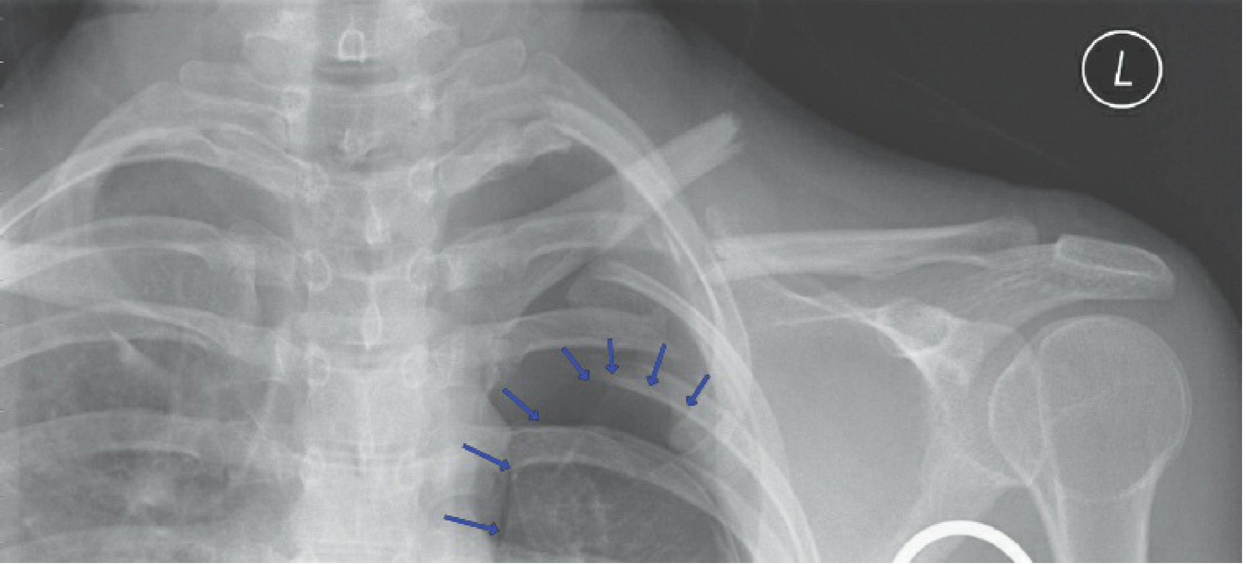
clavicle fracture classification X-ray
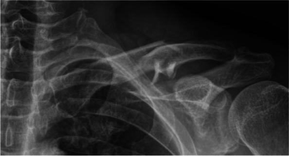
This diagnostic X-ray captures a comminuted fracture of the left clavicle, specifically involving the midshaft or middle third of the bone. The fracture exhibits significant displacement and angulation of the primary medial and lateral bone segments. Multiple smaller fracture fragments are visible at the fracture site, characterizing the injury as comminuted (Robinson classification type 2B2). The superior displacement of the medial fragment is evident, while a notable gap exists between the main segments. Adjacent visible anatomy includes the acromion process of the scapula forming the acromioclavicular joint, the glenohumeral joint with the proximal humerus, the upper rib cage, and the cervical spine vertebrae. No acute abnormalities are seen in the humeral head or the visible portions of the ribs. This image is a primary educational example of orthopedic trauma, illustrating a high-energy clavicular injury and the resulting loss of anatomical alignment often associated with potential neurovascular compression or skin tenting.
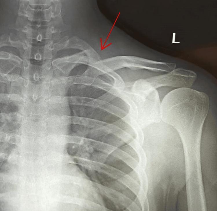
An anterior-posterior (AP) view X-ray of the left shoulder and chest, showing a displaced fracture of the medial end of the clavicle. A red arrow highlights the fracture site, where a clear discontinuity is visible. The medial fragment of the clavicle is displaced superiorly relative to its anatomical position. This finding corresponds to an Edinburgh classification type 1 B1 (displaced extra-articular) fracture. Other visible anatomical structures include the cervical vertebrae, sternum, left rib cage, scapula (including the acromion and glenoid), and the proximal humerus, all of which appear to have normal alignment and no secondary fractures. The image serves as a clinical example of orthopaedic trauma following a high-impact injury, emphasizing the need to assess for potential posterior neurovascular complications due to the proximity of the medial clavicle to the subclavian vessels.
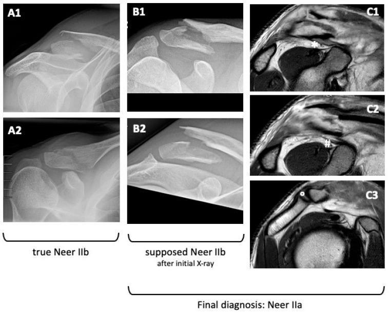
This composite educational image features a Comparison Chart of diagnostic modalities for distal clavicle fractures, contrasting X-ray findings with MRI for classification accuracy. Panels A1-A2 and B1-B2 show standard radiographic views (AP and Rockwood) of distal clavicle fractures. A1-A2 demonstrate a 'true Neer IIb' fracture, characterized by significant superior displacement of the proximal fragment due to coracoclavicular (CC) ligament disruption. Panels B1-B2 display a fracture initially suspected as Neer IIb based on displacement; however, subsequent MRI (panels C1-C3) reveals a different ligamentous status. In the MRI views, the conoid ligament (marked by #) and trapezoid ligament (marked by *) are seen intact and attached to the distal fracture fragment, while the acromioclavicular capsule/ligament (marked by °) is also preserved. This confirms a final diagnosis of Neer IIa. The image serves as a clinical teaching tool for orthopedic surgeons to distinguish between stable and unstable distal clavicle fractures by correlating bony displacement on X-ray with soft-tissue/ligamentous integrity on MRI.
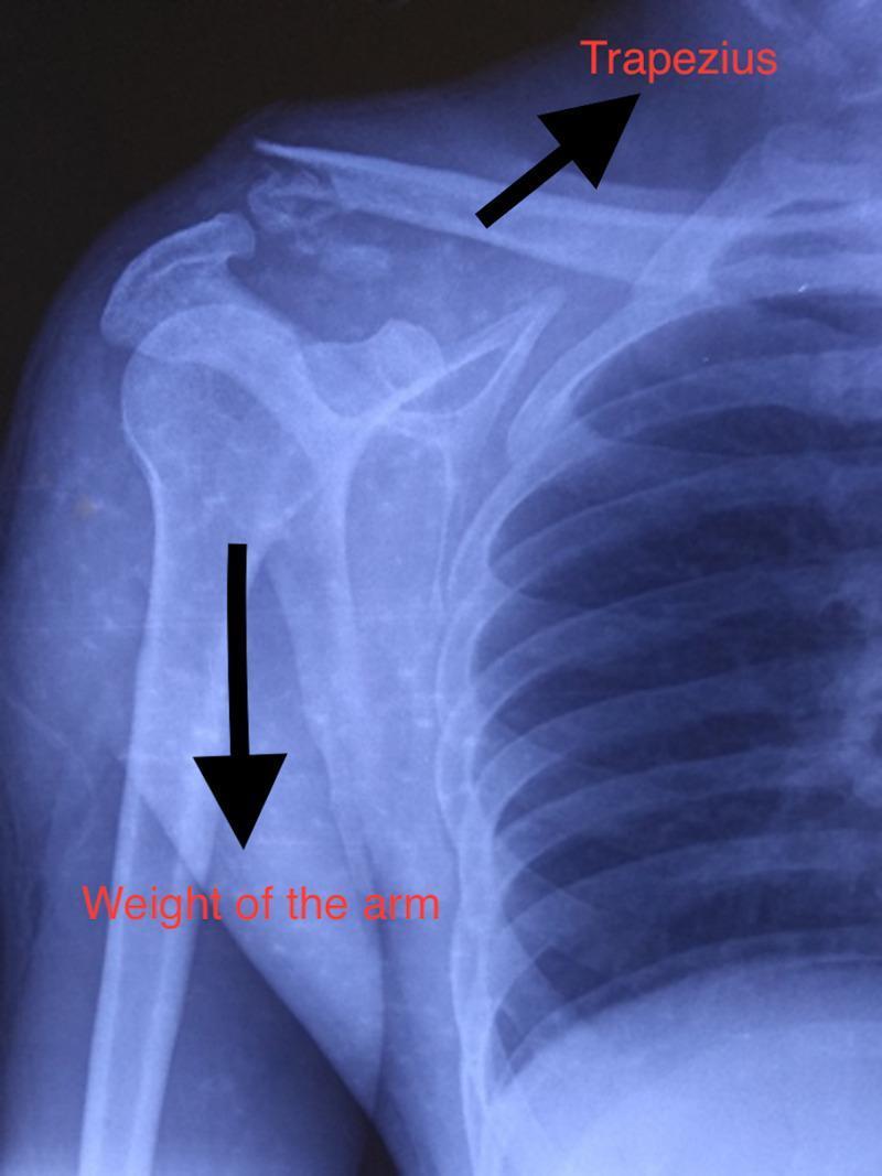
This diagnostic image is an anteroposterior (AP) x-ray of the right shoulder demonstrating a Neer type II lateral end clavicle fracture. The skiagram reveals a complete cortical discontinuity at the distal third of the clavicle with visible comminution and fragmentation at the fracture site. Superior displacement of the proximal clavicular fragment is noted, indicated by an arrow labeled 'Trapezius,' representing the muscular force pulling the bone upward. A corresponding downward arrow labeled 'Weight of the arm' illustrates the gravity-driven inferior displacement of the distal fragment, humerus, and scapula. Other visible anatomical landmarks include the glenohumeral joint, acromion, coracoid process, and upper ribs. The image illustrates the classic displacing forces in distal clavicle fractures where coracoclavicular ligaments are often detached from the proximal segment, leading to instability. This clinical imaging is essential for orthopedic classification and pre-operative planning in trauma cases involving the shoulder girdle.
clavicle fracture anatomy displacement deformity
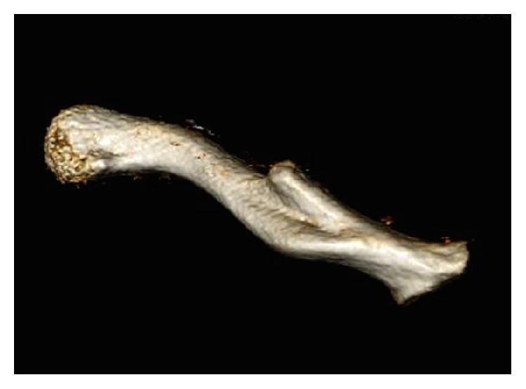
This diagnostic image is a 3D CT reconstruction of a left clavicle, viewed from a posterior perspective against a black background. The image illustrates a significant orthopedic deformity characterized by a malunited midshaft clavicular fracture. The anatomical structure shows a clear disruption of the normal S-shaped contour, with the distal end of the proximal fracture fragment protruding posteriorly, creating a sharp bony prominence and overall angulation. The surface morphology of the bone varies from the smooth, bulbous appearance of the medial end to a rough, irregular texture at the site of bony callus formation and remodeling. This visualization is clinically significant for demonstrating how clavicular malunion can result in posterior displacement, potentially leading to neurovascular complications such as impingement on the subclavian artery or brachial plexus. The content is suitable for orthopedic and radiological educational curricula focusing on fracture healing, malalignment, and thoracic outlet anatomy.
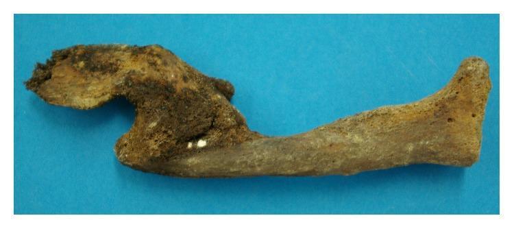
This clinical photograph displays a dry bone specimen of a human clavicle exhibiting an old, healed fracture with significant malunion. The primary pathology is a midshaft clavicular fracture where the dislocated bone ends have fused in an overlapped, non-anatomical position. This remodeling has resulted in a permanent shortening and angular deformity of the bone compared to normal S-shaped clavicular anatomy. A prominent bony callus and irregular overgrowth are visible at the site of fusion, indicating extensive new bone formation and bridging during the healing process. The specimen shows varying degrees of mineralization and taphonomic discoloration, with darker brown areas concentrated around the fracture site and lighter, porous tan areas across the cortical surface. This image serves as a paleopathological example of traumatic bone injury and subsequent biological repair without clinical intervention, illustrating the processes of bone remodeling and fusion after severe displacement.
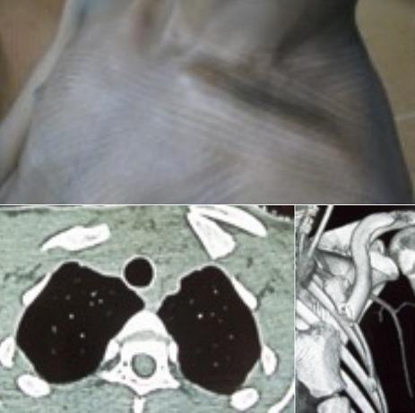
This composite medical image illustrates a complex left clavicle fracture through three distinct modalities: clinical photography, axial computed tomography (CT), and 3D CT reconstruction. The upper clinical photograph shows a visible deformity of the left supraclavicular and sternoclavicular region, characterized by an anterior protrusion of the bone fragment and an associated posterior 'doubling' or displacement. The lower-left axial CT scan at the level of the thoracic inlet demonstrates a fractured clavicle with significant internal rotation and displacement, resulting in a mass effect on the underlying pleural dome. The lower-right 3D reconstruction provides a spatial visualization of the fracture's orientation, showing the nearly 180-degree rotation of the clavicular segment relative to its normal anatomical position. This case serves as an educational example of orthopaedic trauma where severe bony displacement impacts adjacent thoracic structures, specifically highlighting the risk of pleural compression and neurovascular injury in medial clavicle fractures.
Clavicle Fracture - A Detailed Orthopaedic Review
1. Anatomy and Biomechanics
- Medial (SC joint): SC capsule (especially the posterior capsule), interclavicular ligament, and costoclavicular ligaments (most important medial stabilizers against translation)
- Lateral (AC joint and CC ligaments): The coracoclavicular ligaments comprise the trapezoid (more lateral, wider, flat) and conoid (more medial, cone-shaped). These are the primary restraints to superior displacement of the lateral clavicle, and their integrity is critical in distal clavicle fracture management
- Acromioclavicular ligament: Resists anterior/posterior translation at the AC joint
2. Epidemiology
- Account for approximately 2.6% to 4% of all fractures
- Annual incidence: 29-64 per 100,000 persons
- Males predominate in all age groups up to ~60 years, with peak incidence under age 25 and a second smaller peak in middle-aged males
- Location distribution:
- Middle third (diaphyseal): 80-85% of all clavicle fractures
- Distal (lateral) third: 15-20% - more common in elderly from simple falls
- Medial (proximal) third: 0-5% - rarest, often underdiagnosed on plain films; high-energy mechanism with up to 80% associated injury rate
As Hippocrates wrote in 400 BC: "A fractured clavicle, like all other spongy bones, gets speedily united... the patients attach much importance to it... but in a little time the patients, having no pain, nor finding any impediment to their walking or eating, become negligent."
3. Mechanism of Injury
- Most common: Indirect - fall on an outstretched hand (FOOSH) or fall on the point of the shoulder (direct blow transmitted through the acromion)
- Less common: Direct blow to the clavicle itself
- Traction injury: Forceful pulling of the arm away from the body (industrial machinery accidents) - rare
- Birth injury (obstetric fracture): Direct pressure from the symphysis pubis; accounts for ~90% of obstetric fractures and may be associated with brachial plexus palsy
- Pathologic fracture: Always consider if fracture occurs through a lytic lesion with minimal trauma (metastatic disease must be excluded)
- Stress fracture: Repetitive or unusual loads (overhead athletes, throwing sports)
4. Deforming Forces
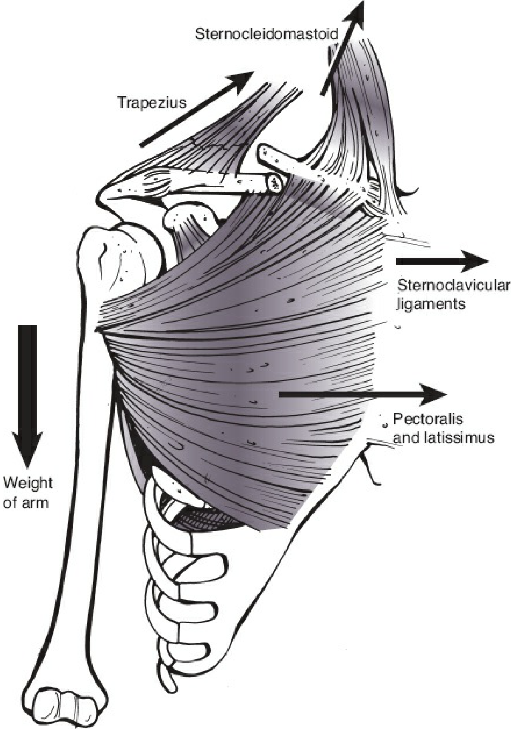
| Fragment | Muscle | Direction |
|---|---|---|
| Proximal (medial) | Sternocleidomastoid | Superior and posterior |
| Distal (lateral) | Weight of arm + Pectoralis major + Latissimus dorsi | Anteroinferior and medial |
| Result | Scapula protraction, shortening, overlap | Characteristic deformity |
5. Classification
A. Allman Classification (original - anatomic)
| Group | Location |
|---|---|
| Group I | Middle third (most common) |
| Group II | Distal/lateral third |
| Group III | Medial/proximal third |
B. Robinson Classification (Edinburgh, preferred in Rockwood & Green)
- 1A: Undisplaced (1A1 extra-articular, 1A2 intra-articular)
- 1B: Displaced (1B1 extra-articular, 1B2 intra-articular)
- 2A: Undisplaced (2A1 cortical alignment, 2A2 angulated)
- 2B: Displaced (2B1 simple/wedge fragment, 2B2 comminuted/segmental)
- 3A: Undisplaced (3A1 extra-articular, 3A2 intra-articular)
- 3B: Displaced (3B1 extra-articular, 3B2 intra-articular)
C. Neer Classification (Lateral/Distal Clavicle Fractures - most clinically used)
| Type | Description | CC Ligaments | Stability |
|---|---|---|---|
| Type I | Fracture distal to the CC ligaments | Intact, attached to distal fragment | Stable |
| Type II | Fracture medial to or through the CC ligaments | Torn from proximal fragment | Unstable (high nonunion risk) |
| Type IIa | Both conoid and trapezoid attached to distal fragment | Partially torn | Less unstable |
| Type IIb | Conoid torn, trapezoid intact on distal fragment | Conoid disrupted | More unstable |
| Type III | Intra-articular fracture extending into AC joint | Intact | Stable |
D. AO/OTA Classification
- 15.1: Proximal (medial) end segment
- 15.2: Diaphyseal segment
- 15.3: Distal (lateral) end segment
- Each subtype: A = extra-articular, B = partial articular, C = complete articular
6. Associated Injuries
- Ipsilateral rib fractures (60% of polytrauma patients with clavicle fracture vs. 29% without)
- Pneumothorax / hemothorax - indicated by severity of trauma
- Scapular neck/glenoid fractures - "floating shoulder" (ipsilateral clavicle + scapular neck fracture = unstable superior shoulder suspensory complex; mortality up to 20-34% in polytrauma)
- Proximal humeral fractures
- Subclavian artery or vein disruption / thrombosis - rare (<1%) but life-threatening; requires CT angiography
- Brachial plexus injury - usually traction type; can be transient
- Head and cervical spine injuries
7. Clinical Features
History
- Mechanism of injury (low energy vs. high energy; direct blow vs. FOOSH)
- Ask about arm dominance, occupation, sporting level - influences treatment decision
- In elderly: rule out pathologic fracture (metastasis)
- Rule out prior injury to the same shoulder
Physical Examination
- Deformity: Visible "tent" of skin over the fracture; step-deformity of shoulder; scapular protraction
- Tenderness: Localized over fracture site; also assess AC joint and SC joint
- Swelling and ecchymosis: Often significant
- Shortening: Compare bilateral clavicle lengths
- Skin integrity: Open fractures are rare but possible; look for skin tenting (impending open fracture)
- Neurovascular exam: Radial pulse, Allen test; upper extremity neurological examination (brachial plexus)
- Cervical spine: Full cervical exam mandatory in any significant trauma
- Respiratory: Auscultate for pneumothorax / hemothorax
- Shoulder girdle: Assess AC joint and SC joint carefully
8. Radiological Evaluation
Standard Views
- AP chest/clavicle radiograph: The first-line investigation; taken standing with arm unsupported to assess true displacement (slings artificially reduce apparent shortening)
- Cephalic tilt view (15-45° cephalad): Removes the overlap of the upper thorax; best for midshaft and distal fractures
- Zanca view: 15° cephalic tilt centered on the AC joint; ideal for distal clavicle fractures
- Apical oblique view: Ipsilateral side rotated 45° with 20° cephalic tilt; good for comminution
- Serendipity view: For SC joint assessment
CT Scanning
- Medial clavicle fractures: CT is the procedure of choice; plain films notoriously underestimate displacement and can miss physeal separations (up to age 25)
- Comminuted fractures: Quantifies fragment number and shortening
- Intra-articular distal fractures: Defines extent of joint involvement
Stress Views
- A 2.25-4.5 kg (5-10 lb) weight suspended from the wrist; taken standing; assesses CC ligament integrity in distal fractures (helps decide between conservative and operative management)
MRI
- Used in selected cases to assess ligamentous status (especially CC ligaments in distal fractures - distinguishes Neer IIa from IIb when plain films are ambiguous)
9. Imaging Examples
10. Treatment
A. Nonoperative Treatment (Standard for Most Fractures)
- Simple sling (arm sling): Standard and sufficient for most fractures; worn for comfort, usually 2-6 weeks
- Figure-of-eight bandage: Historically popular; no proven benefit over sling in multiple RCTs; associated with more discomfort and skin problems - not recommended routinely
- Collar and cuff: Acceptable alternative to sling
- Pendulum exercises from week 1-2
- Active range of motion from weeks 2-4 (when pain allows)
- Strengthening from week 6 onwards
- Full activity typically by 3-6 months
B. Operative Treatment
Indications for Surgery
- Open fracture
- Vascular injury requiring repair
- Progressive neurological deficit
| Fracture Factors | Associated Injury Factors | Patient Factors |
|---|---|---|
| Shortening >2 cm | Vascular injury needing repair | Polytrauma requiring early upper limb weight-bearing |
| Increasing comminution | Progressive neurological deficit | Elite athlete / high functional demand |
| Segmental fracture | Ipsilateral multiple upper rib fractures | High-demand overhead occupation |
| Open fracture | "Floating shoulder" | Patient motivation for rapid return |
| Obvious clinical deformity | Ipsilateral upper extremity fractures | Female sex + unfavorable fracture pattern |
| Scapular malposition/winging |
Surgical Options
1. Plate Fixation (Standard for Midshaft Fractures)
- Superior (anterior-superior) plating is the most common approach
- Pre-contoured anatomic plates are used; locking and non-locking hole options available
- Typical construct: 3-4 bicortical screws on each side of the fracture (6-8 cortices each side)
- Advantages: Rigid fixation, easy reduction, rotational control
- Disadvantages: Prominent hardware requiring removal in up to 30% of patients; wound complications; risk of scar
2. Intramedullary (IM) Nailing
- Uses headed, distally-threaded pins (e.g., modified Hague pin, Rockwood pin, Titanium Elastic Nail)
- Retrograde insertion from posterolateral corner of clavicle, 2-3 cm medial to AC joint
- Advantages: Smaller incision, less soft tissue stripping, easier hardware removal
- Disadvantages: Less rotational control; technically demanding; risk of pin migration; cannot use for very comminuted fractures
- Pin typically removed at 7-8 weeks once union is confirmed
3. Distal Clavicle Fractures (Neer Type II)
- Standard plate fixation is complicated by the short distal fragment and poor cancellous bone quality
- Options include:
- Precontoured distal clavicle plate with multiple 2.7 mm locking screws laterally
- Hook plate: A precontoured plate with a posterior projection inserted into the subacromial space under the acromion - reliable fixation but must be removed at 3-4 months (causes subacromial impingement if left)
- Coracoclavicular suture button: Augments fixation by addressing the CC ligament disruption; used alone or in combination with plate
- AC joint fixation (K-wires + tension band): Generally not preferred due to wire migration risk
4. Medial Clavicle Fractures
- Most treated nonoperatively
- Operative fixation when displaced/unstable; plate can be extended across the SC joint temporarily (3 months to union, then removed)
- Smooth wire fixation is absolutely contraindicated due to risk of mediastinal migration
11. Complications
Early
- Pneumothorax/hemothorax (from rib fractures or direct lung injury)
- Neurovascular injury (subclavian vessels, brachial plexus) - rare (<1%)
- Open fracture - uncommon; skin tenting can progress
Late
Nonunion
- Most common complication of clavicle fracture; occurs in 15-30% of displaced diaphyseal fractures and up to 30% of Neer Type II distal fractures when treated nonoperatively
- Risk factors: Displacement >2 cm, shortening, comminution, female sex, advancing age, smoking, inadequate immobilization
- Classified as atrophic (most common) or hypertrophic
- Treatment: ORIF + bone graft (autologous iliac crest bone graft is gold standard)
- Time to declare nonunion: Lack of radiographic progress for 3+ months or symptomatic at 6 months
Malunion
- Shortening and angular deformity (the scapula protracts and sags)
- Can cause thoracic outlet syndrome, brachial plexus irritation, and cosmetic deformity
- Symptomatic malunion treated with corrective osteotomy and plate fixation
- Strength deficits up to 30% demonstrated on objective testing in malunited clavicles
Post-traumatic Arthritis
- Especially with intra-articular fractures of the AC or SC joints
- May require joint excision (distal clavicle excision or SC joint debridement)
Hardware-related Complications
- Implant prominence requiring removal (up to 30% with superior plating)
- Plate refracture after removal
- Infection (superficial most common; deep rare)
- Symptomatic hardware is the most common reason for re-operation
12. Special Situations
Floating Shoulder
- Ipsilateral fractures of the clavicle and scapular neck/glenoid = disruption of the superior shoulder suspensory complex
- Traditionally treated operatively; evidence supports clavicle fixation alone can indirectly reduce the glenoid, avoiding the need for more complex glenoid surgery
- If glenoid remains displaced after clavicle fixation, posterior approach to glenoid neck is performed
Pediatric Clavicle Fractures
- Most common fracture in children; 90% of obstetric fractures
- Heal reliably with nonoperative treatment
- Remodeling potential is excellent in younger children
- In adolescents: nonoperative is standard; operative indications are the same as adults but surgical intervention should be reserved for older, larger adolescents with severely displaced fractures
- Nonunion is rare (1-3%) in children; beware congenital pseudarthrosis (right-side > left, associated with subclavian artery anomaly or cervical rib)
- Sternoclavicular physeal fracture-dislocation: posterior type requires closed/open reduction with cardiothoracic surgical backup (risk of mediastinal injury)
Pathologic Fractures
- Clavicle is a well-recognized site for metastatic disease (breast, lung, kidney, thyroid, prostate)
- Fracture through a lytic lesion on radiograph mandates full oncologic workup
13. Prognosis and Outcomes
- Outcome measures plateau at approximately 1 year post-injury (DASH, Constant score)
- ~50% of patients report perception of incomplete recovery even years after injury
- Objective strength testing reveals deficits up to 30% that are not apparent on manual muscle testing
- Modern outcome tools (DASH, ASES, Constant score, SF-36) are used in research and clinical follow-up
- Young patients with high-quality bone and anatomically reduced fractures have the best outcomes
- Shortening >2 cm, comminution, and female sex are associated with worse outcomes after nonoperative treatment
Summary Table
| Feature | Middle Third | Distal Third | Medial Third |
|---|---|---|---|
| Frequency | 80-85% | 15-20% | 0-5% |
| Mechanism | FOOSH / direct blow | Simple fall (elderly) | High energy |
| Classification | Allman I / Robinson 2 | Neer / Robinson 3 | Robinson 1 |
| Key imaging | AP + cephalic tilt | AP + Zanca + stress views | CT mandatory |
| Nonunion risk | 15-30% displaced | Up to 30% (Neer II) | Low |
| Standard Rx | Sling ± ORIF | Sling (stable) / ORIF (Neer II) | Sling / ORIF (unstable) |
| Implant of choice | Superior plate / IM nail | Distal plate / Hook plate | Plate (±SC joint spanning) |
Biomechanics of hip joint in detail according to orthopaedics text books
hip joint biomechanics force diagram abductor mechanism
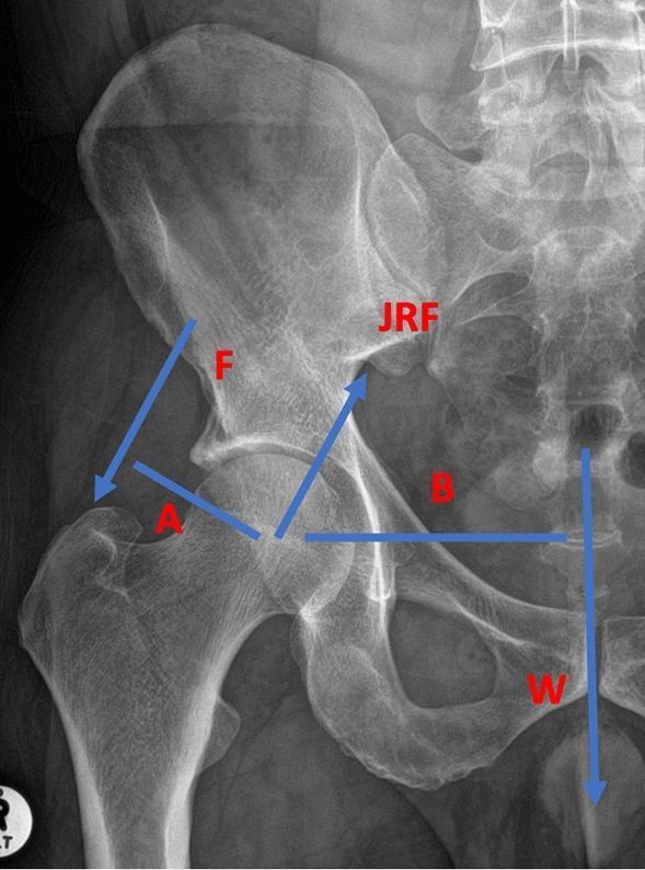
This diagnostic image is an anteroposterior (AP) X-ray of the human right hip joint integrated with a biomechanical free body diagram. Anatomical structures clearly visible include the proximal femur (head, neck, and greater trochanter), the acetabulum of the pelvis, the ilium, and the lower lumbar spine. The diagram overlays several vectors and moment arms to illustrate hip joint loading. The arrow labeled 'F' represents the abductor muscle force acting from the ilium toward the greater trochanter. 'W' denotes the downward force of body weight. 'JRF' indicates the Joint Reaction Force acting across the femoral head and acetabulum. Two blue lines, 'A' and 'B', represent the moment arms for the abductor muscles and body weight, respectively, calculated from the center of rotation of the femoral head. This educational visual is used in orthopedic biomechanics to explain how muscle forces and body weight interact to determine joint stress, which is critical for understanding the pathophysiology of osteoarthritis or the mechanical consequences of corrective osteotomies.
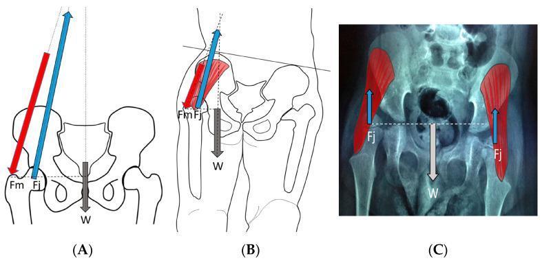
This medical illustration and diagnostic composite compares biomechanical forces acting on the pediatric hip joint across three clinical scenarios. Panel (A) depicts a normal child during the stance phase of gait; a free-body diagram shows the balance between the body weight moment (W, downward vector), the abductor muscle force (Fm, downward-lateral vector), and the resulting hip joint reaction force (Fj), which is directed medially into the acetabulum at an oblique angle. Panel (B) illustrates a weak or hypotonic ambulatory child with a trunk lurch; here, the abductor force (Fm) is significantly reduced, resulting in a more vertically oriented and smaller joint reaction force (Fj). Panel (C) presents an anteroposterior pelvic radiograph of a child in static standing, with superimposed vector analysis; in this state, the joint reaction force (Fj) is minimal and purely vertical, counteracting approximately half of the body weight (W). The diagrams illustrate how gait and muscle tone influence the magnitude and direction of hip impulse, which are critical factors in the development of the femoral neck-shaft angle and acetabular depth.
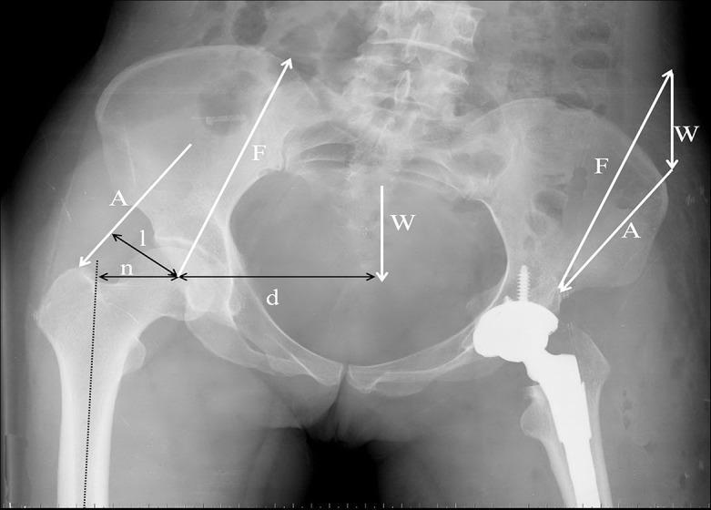
Anteroposterior (AP) radiograph of a human pelvis and both hips demonstrating biomechanical force vectors and lever arms. The right hip (image left) shows native anatomy, while the left hip (image right) features a total hip arthroplasty (THA) with a visible femoral stem and acetabular component. Overlaid on the native hip, white arrows represent the abductor muscle force (A) and the joint reaction force (F). A downward arrow (W) at the pelvic midline represents the body's gravitational force. On the native side, specific measurements are annotated: 'n' (femoral offset) indicates the horizontal distance between the femoral longitudinal axis and the center of rotation; 'l' represents the abductor muscle moment arm; and 'd' represents the gravitational force moment arm extending from the hip center to the midline. The diagram illustrates the equilibrium of forces required for a single-leg stance, highlighting how femoral anatomy and prosthetic placement influence the mechanical advantage of the abductor muscles and the resulting joint reaction forces.

This diagnostic image is a coronal X-ray (radiograph) of the human pelvis and proximal femurs, overlayed with a biomechanical diagram to illustrate the physics of hip stability. The anatomical structures include the iliac wings, sacrum, pubic symphysis, and femoral heads articulating with the acetabula. The diagram represents the hip joint as a first-class lever system. A black triangle marks the center of the femoral head as the fulcrum. A large white arrow descending through the pelvic midline represents the force of body weight, while a gray arrow at the greater trochanter represents the counteracting force of the abductor muscles. A horizontal black line indicates the respective lever arms: 'L' denotes the short abductor lever arm and '2L' denotes the longer lever arm of body weight. The image is used to demonstrate how horizontal displacement in conditions like sacral perineural cysts (SPD) or pelvic fractures can extend the body weight lever arm, increasing the mechanical work and muscle force required to maintain pelvic balance.
Biomechanics of the Hip Joint
1. Structural Overview and Joint Type
| Axis | Movements |
|---|---|
| Transverse axis | Flexion and extension |
| Sagittal (anteroposterior) axis | Abduction and adduction |
| Longitudinal (vertical) axis | Internal and external rotation |
2. Stabilisers of the Hip Joint
Static Stabilisers
- Bony containment: The deep acetabular socket and the labrum together contain approximately 170° of the femoral head, providing inherent stability not achievable in shallower joints
- Acetabular labrum: A fibrocartilaginous ring (triangular in cross-section) attached to the acetabular rim; deepens the socket, enhances stability, acts as a fluid seal improving joint lubrication, and creates a suction effect that resists distraction forces
- Joint capsule: Forms a strong fibrous sleeve; particularly reinforced anteriorly
- Ligaments:
- Iliofemoral ligament (Y-ligament of Bigelow): Strongest ligament in the body; resists extension and external rotation
- Pubofemoral ligament: Anteroinferior; resists abduction and external rotation
- Ischiofemoral ligament: Posterior; resists extension and internal rotation
- Ligamentum teres: Intra-articular; minor mechanical role but carries a branch of the obturator artery to the femoral head (important in children)
Dynamic Stabilisers
| Group | Muscles | Position |
|---|---|---|
| Abductors | Gluteus medius, gluteus minimus, tensor fasciae latae | Lateral |
| Flexors | Iliopsoas (primary), rectus femoris | Anterior |
| Extensors | Gluteus maximus, hamstrings | Posterior |
| Short external rotators | Piriformis, obturator internus/externus, gemelli, quadratus femoris | Posteroinferior |
3. Range of Motion
| Motion | Average Range (degrees) | Functional Range (degrees) |
|---|---|---|
| Flexion | 115° | 90° (120° to squat) |
| Extension | 30° | - |
| Abduction | 50° | 20° |
| Adduction | 30° | - |
| Internal rotation | 45° | 0° |
| External rotation | 45° | 20° |
4. Joint Reaction Force (JRF) - The Core Principle
The Lever Arm Problem
- The body weight (acting through the centre of gravity of the body above, approximately at the midline) acts on a long lever arm (~3x the abductor moment arm)
- The hip abductors (gluteus medius/minimus) insert at the greater trochanter on a short lever arm (~1/3 the body weight lever arm)
- To achieve rotational equilibrium (prevent the pelvis from dropping on the swing side), the abductors must generate a force approximately 3x body weight
- W = body weight
- Body weight acts at distance 3x from the hip centre
- Abductor force acts at distance x from the hip centre
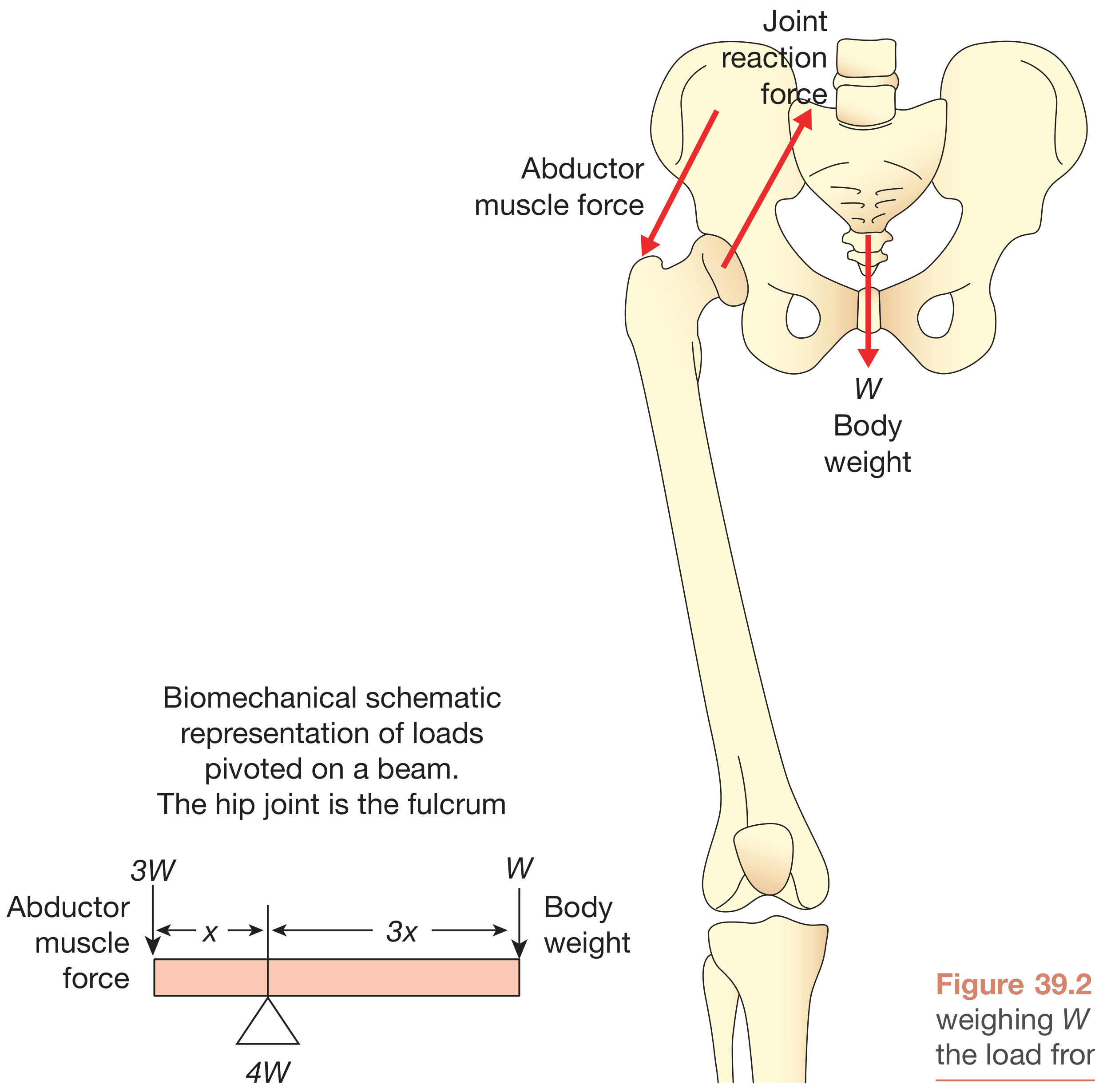
JRF Across Activities (Bailey & Love)
| Activity | Joint Reaction Force |
|---|---|
| Lying supine (lifting leg from bed) | ~1.5 × body weight |
| Standing on two legs | ~0.5-1 × body weight |
| Walking (stance phase) | 3 × body weight |
| Standing on one leg | 4 × body weight |
| Activities of daily living | Up to 3× body weight |
| Running / physically demanding | Up to 8-10 × body weight |
| Hopping on one leg | Up to 10 × body weight |
5. The Sourcil and Gothic Arch - Adaptation to JRF
- Sourcil (French: "eyebrow"): A condensation of subchondral bone beneath the superomedial acetabulum, where the JRF is maximal. Visible on AP pelvis X-ray as a dense white arc. Loss of the sourcil indicates joint space narrowing and abnormal load distribution
- Gothic arch: Remodelled trabecular bone supporting the acetabular roof, with the sourcil at its base; reflects the dominant loading direction
6. Femoral Neck-Shaft Angle (CCD Angle) and Its Biomechanical Effects
- Normal: ~126° (range: 120°-135°)
- Coxa valga: CCD angle > 135°
- Coxa vara: CCD angle < 120°
Effects of Altered CCD Angle
| Parameter | Coxa Vara (CCD < 120°) | Normal (~126°) | Coxa Valga (CCD > 135°) |
|---|---|---|---|
| Abductor moment arm (D) | Increased (D') | Normal | Decreased (D'') |
| JRF | Decreased (R = ~3K) | Normal (R = ~4K) | Increased (R = ~7K) |
| Bending moment across femoral neck | Decreased | Normal | Increased |
| Shear force across femoral neck | Increased | Normal | Decreased |
| Abductor muscle length | Decreased | Normal | Increased |
| Acetabular stress | Decreased | Normal | Increased |
| Risk of femoral neck fracture | Higher (shear) | Normal | Higher (stress) |
| Clinical tendency | Limp, shortening | Normal | OA, stress failure |
7. Femoral Offset
- Femoral offset = the abductor moment arm (lever arm)
- Greater offset → greater abductor mechanical advantage → lower required abductor muscle force → lower JRF
- Restoring offset in total hip arthroplasty (THA) is critical: reducing offset increases JRF, reduces abductor efficiency, causes a Trendelenburg limp, and increases polyethylene wear
8. Femoral Neck Anteversion
- Normal anteversion: 10°-15° in adults (up to 30-40° in infants, decreasing with growth)
- Excessive anteversion: "In-toeing" gait, increased risk of hip impingement, anterior instability
- Retroversion: "Out-toeing" gait, predisposes to femoroacetabular impingement (FAI) - Cam and Pincer types
- The combined anteversion (femoral + acetabular) determines the functional range of internal and external rotation
9. Acetabular Orientation - Inclination and Anteversion
- Acetabular inclination (abduction angle): Normal = 40°-45° from horizontal
-
55°: "Open" socket - insufficient coverage, increased risk of dislocation
- < 35°: Excessive coverage, risk of impingement
-
- Acetabular anteversion: Normal = 15°-25°
- Retroversion: Risk of posterior impingement and dysplasia
- Excessive anteversion: Risk of anterior instability
10. Effects of the Acetabular Labrum on Biomechanics
- Deepens the socket: Increases the area of contact between the femoral head and acetabulum, thereby reducing contact stress (stress = force / area)
- Fluid pressurisation: Acts as a fluid seal, trapping and pressurising synovial fluid within the joint space. This maintains hydrostatic pressure that supports the cartilage and dramatically reduces friction (the "squeeze film" lubrication mechanism)
- Suction seal: Creates negative intra-articular pressure that resists femoral head distraction (up to 40% of hip stability is contributed by the labral suction seal)
11. Articular Cartilage and Lubrication
- Articular cartilage is porous and elastic
- Under load, fluid is squeezed out of the cartilage, forming a thin lubricating film between joint surfaces
- As load is removed, fluid is resorbed back into cartilage
- This mechanism relies on the labral fluid seal and the biphasic nature of cartilage (solid matrix + interstitial fluid)
- Boundary lubrication: Lubricin (PRG4) adsorbs to cartilage surface; acts at low sliding speeds
- Weeping lubrication: Hydrostatic pressure drives fluid from cartilage to the surface
- Boosted lubrication: Fluid moves into the cartilage at high loads, concentrating macromolecules (hyaluronic acid) that coat the surface
12. Trendelenburg Sign - Clinical Application of Abductor Biomechanics
- Weak abductors (neurological: superior gluteal nerve palsy; myopathic; painful inhibition)
- Shortened abductor moment arm (coxa valga; previous hip surgery; lateralised acetabulum)
- Pain inhibition (most common cause in clinical practice - any painful hip condition)
13. Gait Cycle and Hip Biomechanics
| Phase | Hip Position | JRF |
|---|---|---|
| Loading response (initial contact) | Flexion ~30° | Rising rapidly to 3-4W |
| Mid-stance | Neutral to slight extension | Peak ~3-4W |
| Terminal stance | Extension ~10°-15° | Moderate |
| Pre-swing (toe-off) | Extension ~20° | Second peak ~2-3W |
| Swing | Flexion | Near zero |
- Flexion: 30°-40°
- Extension: 10°-15°
- Abduction: 5°-10°
- Rotation: 5°
- A cane in the contralateral hand reduces JRF significantly by providing an external force that reduces the required abductor muscle force
- Body weight moment arm × W = abductor moment arm × (abductor force - cane contribution) → net reduction in JRF by ~30-40%
- This explains why patients with hip OA intuitively use a cane in the opposite hand
14. Effect of Hip Arthrodesis on Biomechanics
- 25°-30° flexion
- 0°-5° adduction
- 5°-10° external rotation
- Oxygen consumption increases
- Gait efficiency decreases to ~50% of normal
- Increases transpelvic rotation at the contralateral hip (long-term risk of contralateral hip OA)
- Increases lumbar spine and knee joint stress (late complications)
- If fused in abduction: excessive trunk shift and eventual low back pain
15. Clinical Biomechanical Strategies to Reduce Hip JRF
| Strategy | Mechanism | Effect on JRF |
|---|---|---|
| Cane (contralateral hand) | Reduces required abductor force | Decreased |
| Weight loss | Reduces body weight W | Decreased |
| Duchenne lurch | Moves centre of gravity toward hip centre (reduces body weight moment arm) | Decreased |
| Carrying a load on the affected side | Moves partial-body COG toward hip centre | Decreased |
| Varus osteotomy | Increases abductor moment arm | Decreased |
| THA with restored offset | Restores abductor moment arm | Normalised |
| THA with medialised cup | Increases abductor moment arm | Decreased |
| Limping on the affected side (lurch) | Compensatory biomechanical adaptation | Decreased |
| Running / jumping | Increases dynamic muscle forces | Greatly increased (8-10W) |
16. Blood Supply of the Femoral Head - Biomechanical Relevance
- Femoral neck fractures - intracapsular fractures strip the retinacular vessels → avascular necrosis (AVN)
- Hip dislocations - tension or tear of the retinacular branches
- Coxa valga - alters tension on the capsule and retinacular vessels
Summary of Key Biomechanical Concepts
| Concept | Key Value / Principle |
|---|---|
| Joint type | Ball-and-socket; 3 degrees of freedom |
| JRF - standing on one leg | 4 × body weight |
| JRF - running/jumping | 8-10 × body weight |
| Abductor force (single-leg stance) | 3 × body weight |
| Lever arm ratio | Body weight arm : abductor arm = 3:1 |
| Normal CCD angle | 126° (120°-135°) |
| JRF in coxa valga | Increased (~7K) |
| JRF in coxa vara | Decreased (~3K) |
| Coefficient of friction (normal joint) | 0.002-0.04 |
| Primary lubrication mechanism | Elastohydrodynamic |
| Sourcil | Peak JRF zone - superomedial acetabulum |
| Trendelenburg sign | Failure of abductor mechanism |
| Cane effect | ~30-40% reduction in JRF |
| Arthrodesis optimal position | 25-30° flex, 0-5° add, 5-10° ER |