
Direct and indirect tooth coloured restorations for 25 marks . Give me answer from contents to references . Also give me hand drawn images
composite resin direct tooth coloured restoration cavity preparation
ceramic inlay onlay indirect tooth coloured restoration
Hand-drawn educational dental diagram showing: (1) Direct tooth-coloured restoration steps - a tooth cross-section showing cavity preparation, acid etching, bonding agent application, composite resin placement in increments, and light curing with UV lamp. Labels in clear handwriting style. (2) Indirect restoration types - inlay (within cusps), onlay (covering one or more cusps), and veneer on anterior tooth. Black ink sketch style on white background with neat handwritten labels.
Hand-drawn dental science diagram showing composition of composite resin: a labeled sketch with three components - organic resin matrix (Bis-GMA), inorganic filler particles (silica/glass), and silane coupling agent connecting them. Also showing types of composite by filler size: macrofill, microfill, hybrid, nanofill arranged as a comparison chart. Black pen sketch style on white background with clear handwritten annotations.
Hand-drawn dental diagram showing ceramic restoration types: porcelain veneer preparation (labial reduction 0.5mm), ceramic inlay cavity design (box form, rounded internal angles), and ceramic crown with margin types (shoulder, chamfer, feather edge). Also a small sketch of a dental furnace/pressing equipment used for indirect ceramic fabrication. Black ink educational sketch style, white background, neat handwritten labels.
Direct and Indirect Tooth-Coloured Restorations
Contents
- Introduction
- Direct Tooth-Coloured Restorations
- 2.1 Composite Resin
- 2.2 Glass Ionomer Cement (GIC)
- 2.3 Resin-Modified GIC (RMGIC)
- 2.4 Compomers
- Indirect Tooth-Coloured Restorations
- 3.1 Ceramic Inlays and Onlays
- 3.2 Porcelain Veneers
- 3.3 Ceramic Crowns
- Comparison: Direct vs Indirect
- Clinical Indications and Contraindications
- Advantages and Disadvantages
- References
1. Introduction
- Direct - placed chairside in a single visit (e.g., composite resin, GIC)
- Indirect - fabricated in a dental laboratory and cemented at a second visit (e.g., ceramic inlays, veneers, crowns)
2. Direct Tooth-Coloured Restorations
2.1 Composite Resin
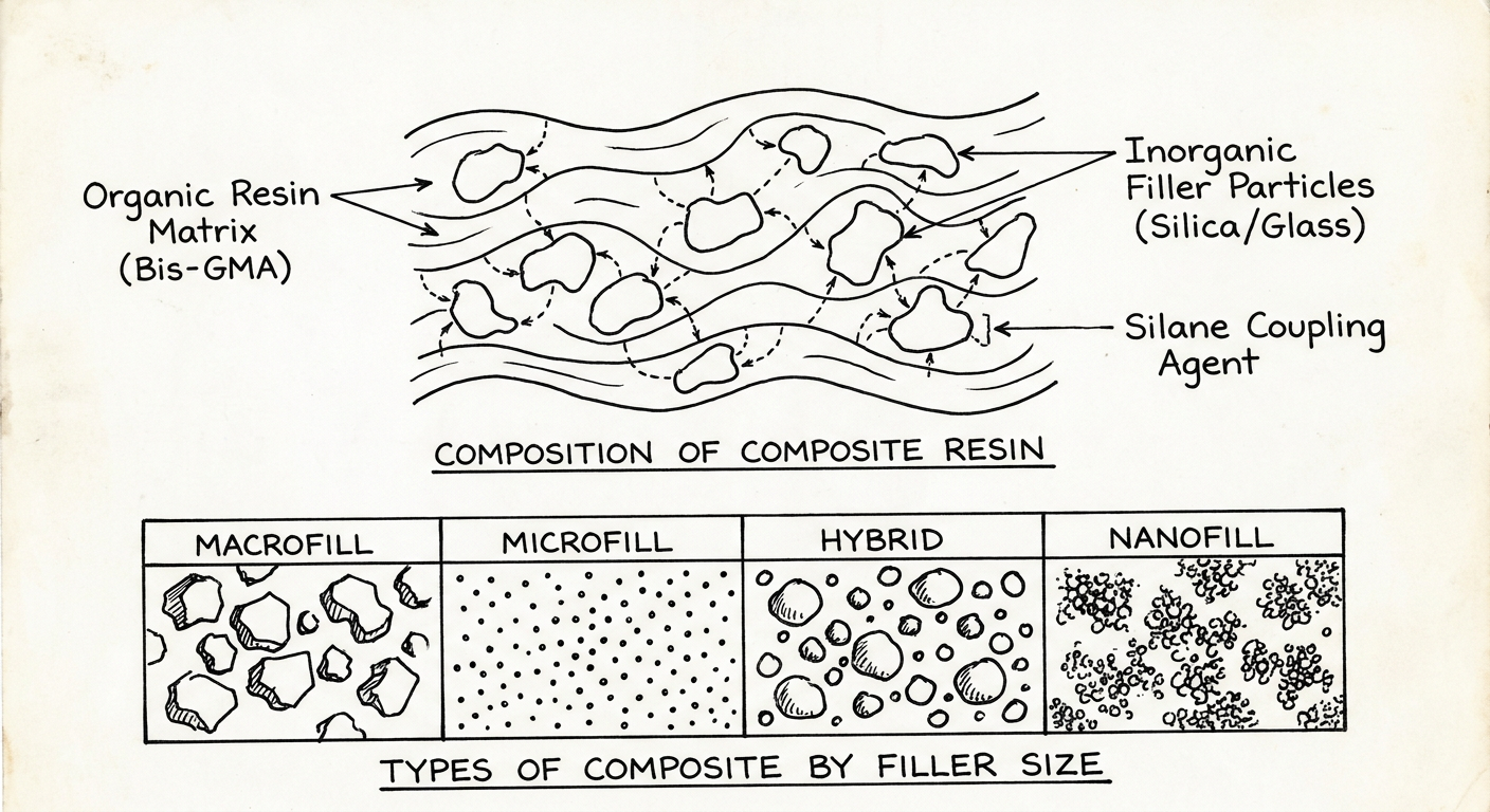
| Component | Material | Function |
|---|---|---|
| Organic matrix | Bis-GMA, TEGDMA, UDMA | Provides plasticity and polymerization |
| Inorganic filler | Quartz, glass, silica | Strengthens, reduces shrinkage |
| Coupling agent | Silane | Bonds filler to matrix |
| Initiator | Camphorquinone (light cure) | Initiates polymerization |
| Inhibitor | BHT | Prevents premature setting |
| Type | Filler Size | Use |
|---|---|---|
| Macrofill | 10-100 µm | Posterior load-bearing (obsolete) |
| Microfill | 0.01-0.1 µm | Anterior aesthetics |
| Hybrid | 1-10 µm + microfill | Universal use |
| Nanofill | < 0.1 µm | High polish, anterior |
| Packable | 10-50 µm | Class I, II posterior |
| Flowable | Low filler % | Lining, pits and fissures |
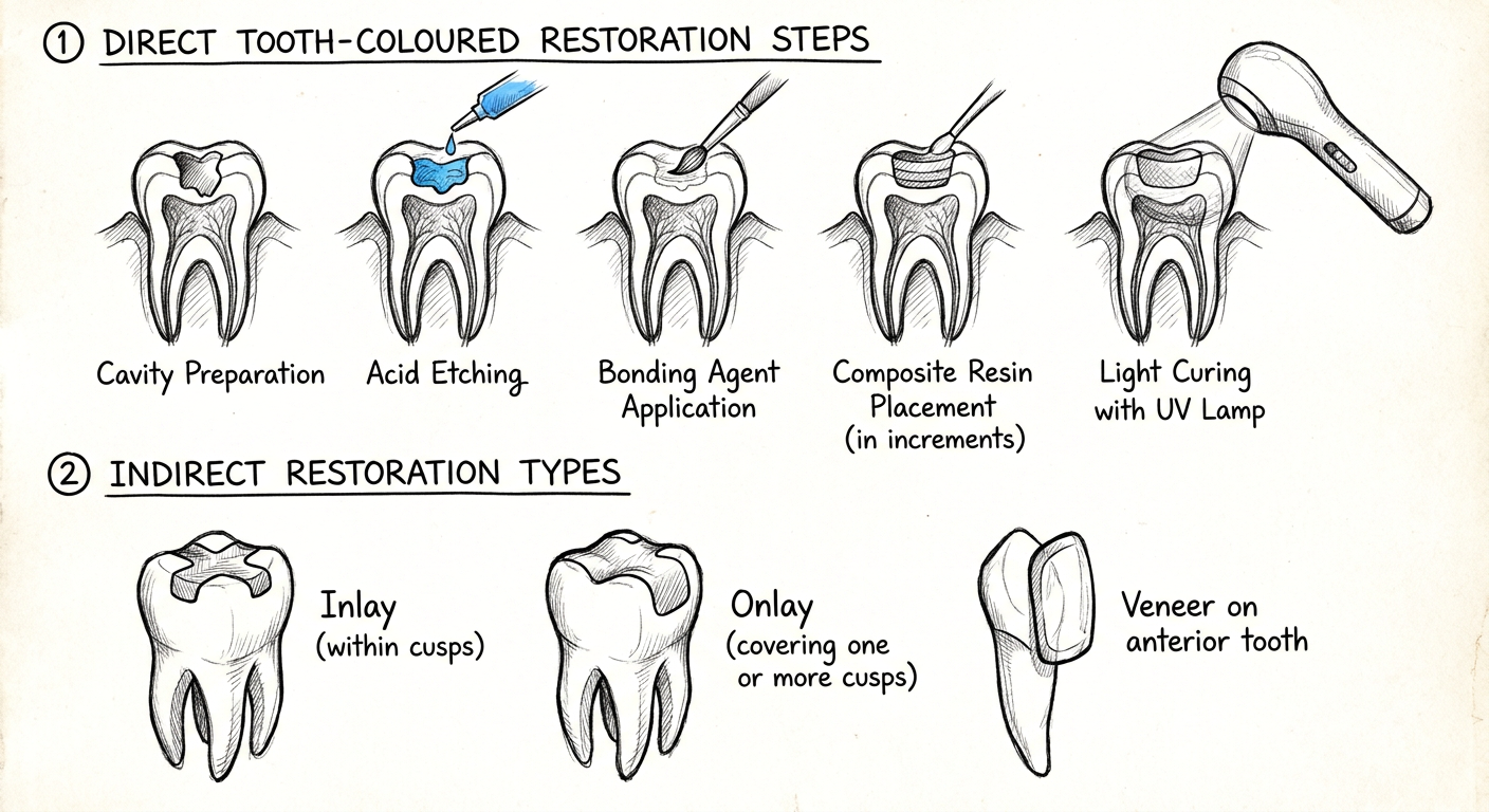
- Shade selection - Before isolation, under natural light
- Cavity preparation - Conservative; no undercuts needed (adhesive retention). Bevel enamel margins 45° for anterior teeth
- Isolation - Rubber dam mandatory
- Acid etching - 37% orthophosphoric acid; enamel 30 sec, dentine 15 sec; rinse, leave slightly moist (wet bonding)
- Bonding agent - Total-etch or self-etch system applied and light-cured
- Composite placement - Incremental technique; each increment ≤ 2mm to minimize polymerization shrinkage
- Light curing - 20-40 sec per increment (LED lamp, 450-500 nm)
- Finishing and polishing - Carbide burs, Sof-Lex discs, polishing paste
- Occlusal check - Articulating paper; adjust contacts
- Incremental placement (oblique layering technique)
- Low C-factor cavities
- Use of low-shrinkage monomers (Silorane-based)
- To enamel: micromechanical (acid etching creates tags)
- To dentine: hybrid layer formation (Nakabayashi, 1982) - resin monomers infiltrate demineralized collagen network
2.2 Glass Ionomer Cement (GIC)
- Powder: Fluoroaluminosilicate glass
- Liquid: Polyacrylic acid + water
| Type | Use |
|---|---|
| Type I | Luting cement |
| Type II | Restorative (anterior, Class III, V) |
| Type III | Lining/base |
| Type IV | Fissure sealant |
2.3 Resin-Modified GIC (RMGIC)
2.4 Compomers (Polyacid-Modified Composite Resins)
3. Indirect Tooth-Coloured Restorations
- Large cavities (> 2/3 intercuspal width)
- Need for cuspal coverage
- Complex occlusal morphology
- Repeated failure of direct restorations
- Tooth fracture, cracked tooth syndrome
- Tooth preparation
- Impression (conventional or digital/intraoral scan)
- Temporary restoration
- Lab fabrication (wax-up → press/mill ceramic)
- Try-in
- Cementation (adhesive or conventional)
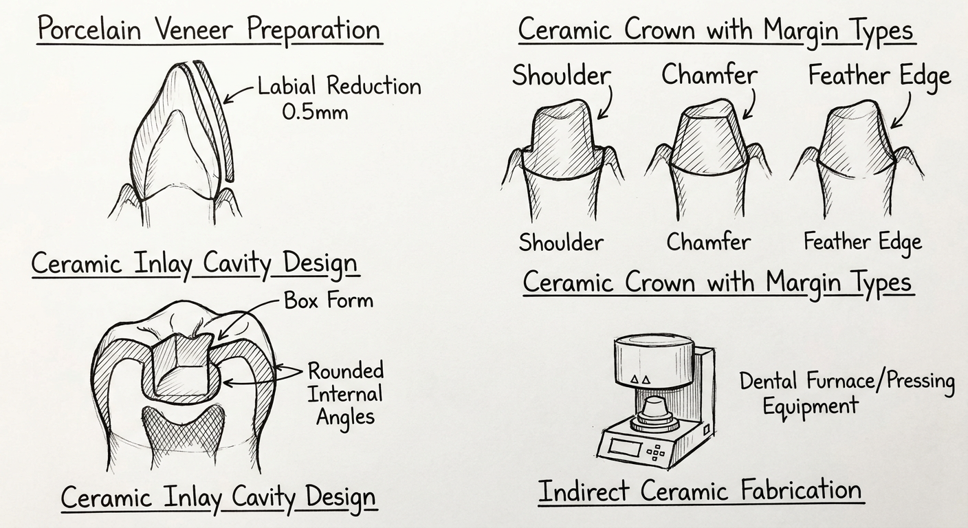
3.1 Ceramic Inlays and Onlays
- Inlay: Intracoronal restoration confined within the cusps
- Onlay: Extends over one or more cuspal inclines (partial coverage crown)
- Overlay: Covers all cusps
- Occusal divergence: 10-15° (prevents binding)
- Rounded internal line angles
- Flat pulpal and gingival floors
- No undercuts (filled with GIC liner)
- Minimum depth: 1.5mm (for adequate ceramic thickness)
- Isthmus width: > 2mm
- Feldspathic porcelain (traditional, excellent aesthetics, technique-sensitive)
- Leucite-reinforced ceramic (IPS Empress)
- Lithium disilicate (IPS e.max - most popular, flexural strength 360-400 MPa)
- Zirconia (posterior, high strength 900+ MPa, poor aesthetics)
- CAD/CAM milled ceramic (CEREC - chairside in single visit)
- Adhesive resin cement (Panavia, RelyX) - preferred; increases fracture resistance
- Etching porcelain with 5-9% hydrofluoric (HF) acid creates microtags
- Silane coupling agent applied to ceramic surface before cementation
3.2 Porcelain Veneers
- Discolouration (tetracycline staining, fluorosis)
- Enamel defects (hypoplasia, erosion)
- Mild spacing (diastema closure)
- Minor malposition
- Peg laterals
- Fractures
- Insufficient enamel (< 50% bonding surface)
- Parafunctional habits (bruxism)
- Excessive overjet or deep overbite
- Labial reduction: 0.5mm (within enamel)
- Cervical finish line: Chamfer at or just subgingival
- Incisal designs: Window (no incisal coverage), feather edge, or butt joint (incisal overlap - stronger)
- Interproximal extension: Through contact point
- Try-in with glycerine gel (water-soluble try-in paste)
- Clean tooth: pumice, no fluoride
- Etch tooth enamel: 37% H₃PO₄
- Etch porcelain: 5-9% HF acid (90 sec for feldspathic; 20 sec for pressed ceramic)
- Apply silane to ceramic; bonding agent to tooth
- Light-cured resin cement (shade selection important)
- Remove excess cement; cure all margins
3.3 All-Ceramic Crowns
| System | Material | Strength | Application |
|---|---|---|---|
| IPS e.max Press/CAD | Lithium disilicate | 360-400 MPa | Anterior + premolar |
| IPS Empress | Leucite ceramic | 120-180 MPa | Anterior only |
| Zirconia | Y-TZP | 900-1200 MPa | Posterior, implant crowns |
| Procera | High-purity alumina | 600 MPa | Anterior |
- Occlusal/incisal reduction: 1.5-2mm
- Axial reduction: 1-1.5mm all around
- Finish line: Shoulder or deep chamfer (360°)
- No sharp line angles
- Minimum taper: 6° total convergence angle
4. Comparison: Direct vs Indirect TCR
| Feature | Direct (Composite) | Indirect (Ceramic) |
|---|---|---|
| Visits | Single visit | Multiple visits |
| Cost | Lower | Higher |
| Polymerization shrinkage | Present (in vivo) | Eliminated (ex vivo) |
| Occlusal accuracy | Less precise | Excellent (lab articulated) |
| Wear resistance | Lower | Superior |
| Marginal fit | Good | Excellent |
| Fracture toughness | Lower | Higher (e.max) |
| Repairability | Easy (can add composite) | Difficult |
| Tooth removal | Conservative | Moderate |
| Fluoride release | None (composite alone) | None |
5. Clinical Indications and Contraindications
- Class I, II, III, IV, V cavities
- Small-medium sized cavities
- Paediatric patients
- Provisional restorations
- Repair of ceramic/amalgam
- Large posterior restorations with cuspal involvement (consider indirect)
- Heavy bruxism
- Inability to achieve adequate isolation
- Large cavities with cuspal coverage needed
- Aesthetic rehabilitation (veneers)
- Tooth fracture
- Post-endodontic crowning
- High aesthetic demand
- Insufficient ferrule for crown (< 2mm)
- Active caries not controlled
- Parafunctional habits (relative contraindication)
- Economic constraints
6. Advantages and Disadvantages
Composite Resin
GIC
Ceramic Inlays/Onlays/Veneers
References
- Roberson TM, Heymann HO, Swift EJ. Sturdevant's Art and Science of Operative Dentistry. 5th ed. Mosby; 2006.
- Craig RG, Powers JM. Restorative Dental Materials. 11th ed. Mosby; 2002.
- Summitt JB, Robbins JW, Schwartz RS. Fundamentals of Operative Dentistry: A Contemporary Approach. 3rd ed. Quintessence; 2006.
- Wilson AD, Kent BE. A new translucent cement for dentistry: the glass ionomer cement. Br Dent J. 1972;132(4):133-135.
- Nakabayashi N, Kojima K, Masuhara E. The promotion of adhesion by infiltration of monomers into tooth substrates. J Biomed Mater Res. 1982;16(3):265-273.
- Dietschi D, Spreafico R. Adhesive Metal-Free Restorations. Quintessence; 1997.
- Mörmann WH. The evolution of the CEREC system. J Am Dent Assoc. 2006;137(Suppl):7S-13S.
- Kelly JR. Ceramics in restorative and prosthetic dentistry. Annu Rev Mater Sci. 1997;27:443-468.
- Van Meerbeek B et al. Adhesion to enamel and dentin: current status and future challenges. Oper Dent. 2003;28(3):215-235.
- Brogdon BG. Forensic Radiology. CRC Press; 1998. Chapter 10: Dental identification - Dental restorative materials.
Exam Tip (25-mark question structure): This answer covers ~6 marks for direct restorations (composite composition + technique), ~4 marks for GIC/RMGIC/compomers, ~8 marks for indirect restorations (inlays, veneers, ceramics), ~4 marks for comparison/indications, and ~3 marks for advantages/disadvantages + references. Adjust depth per your university's marking scheme.
Fibre reinforced composites for 10 marks with contents and references
Hand-drawn educational dental diagram of fibre reinforced composite (FRC): showing cross-section with glass fibres (long parallel lines) embedded in resin matrix, different fibre orientations (unidirectional, bidirectional woven, random/isotropic), and a clinical sketch of FRC fixed partial denture (Maryland bridge) replacing a missing tooth with fibre ribbon visible under pontic. Black ink sketch style on white background with neat handwritten labels.
Hand-drawn science diagram showing fibre volume fraction and stress transfer in fibre reinforced composite: left sketch shows unidirectional fibres (parallel lines) with stress arrows parallel to fibre axis showing maximum strength; middle sketch shows bidirectional woven fibres (crosshatch pattern); right sketch shows random short fibres (scattered lines) showing isotropic properties. Below: a simple bar chart comparing flexural strength values - unreinforced resin 80 MPa, short fibre FRC 150 MPa, unidirectional FRC 700 MPa. Black ink hand-drawn style, white background, clear handwritten labels and arrows.
Fibre Reinforced Composites (FRC)
Contents
- Introduction and Historical Background
- Composition of FRC
- Types of Fibres
- Fibre Architecture / Orientation
- Mechanism of Reinforcement
- Clinical Applications
- Advantages and Disadvantages
- Failures and Their Management
- References
1. Introduction and Historical Background
- First introduced in dentistry in the 1960s using carbon/graphite fibres for denture base reinforcement.
- Glass fibre-reinforced composites for prosthetic and restorative use gained momentum in the 1990s with the work of Vallittu and Freilich.
- Today FRCs are used for fixed partial dentures (FPDs), periodontal splints, post-and-core systems, orthodontic retainers, and denture bases.
2. Composition of FRC
2.1 Reinforcing Fibres
2.2 Resin Matrix
- Most commonly: Bis-GMA, TEGDMA, PMMA (for denture base), or epoxy resins.
2.3 Silane Coupling Agent
- Applied to fibre surface before embedding in matrix.
- Creates a chemical bond between the inorganic fibre surface and organic resin matrix.
- Critical for interfacial adhesion - without silane, fibres simply pull out of the matrix (poor stress transfer).
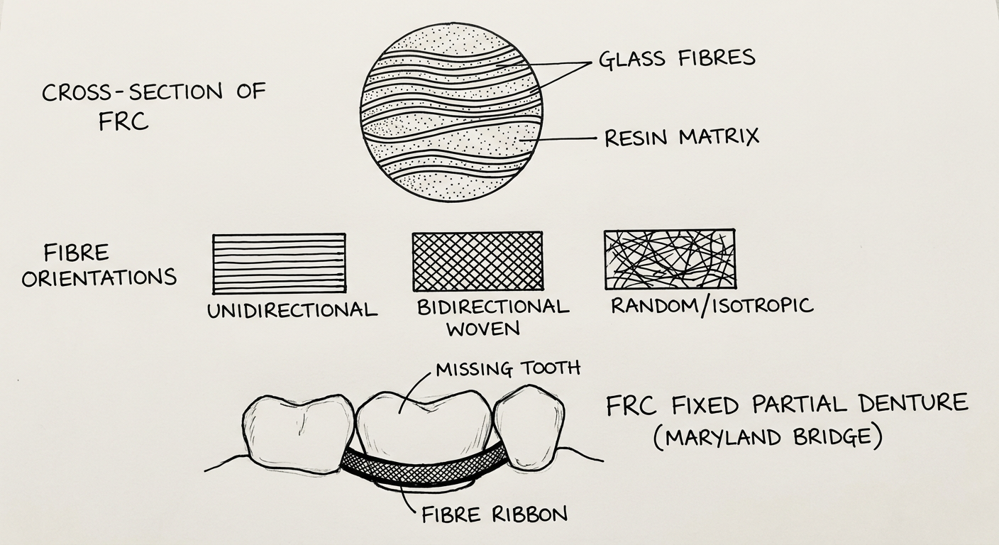
3. Types of Fibres Used in Dental FRC
| Fibre Type | Material | Properties | Use |
|---|---|---|---|
| E-glass fibres | Borosilicate glass | Most widely used; good aesthetics, biocompatible, can be silanated | FPDs, splints, posts |
| S-glass fibres | Aluminium-magnesia-silicate glass | Higher strength and stiffness than E-glass | High-load applications |
| Carbon / Graphite fibres | Carbon | Very high strength and stiffness; opaque (dark) | Denture reinforcement (not anterior) |
| Polyethylene fibres | Ultra-high molecular wt PE (Dyneema, Ribbond) | Excellent toughness and tensile strength; tooth-coloured | Periodontal splints, retainers |
| Aramid fibres | Kevlar | High tensile strength; yellow colour, difficult to finish | Limited dental use |
| Quartz fibres | Pure silica | Superior aesthetics (most translucent), high strength | Anterior FPDs, where aesthetics critical |
4. Fibre Architecture / Orientation
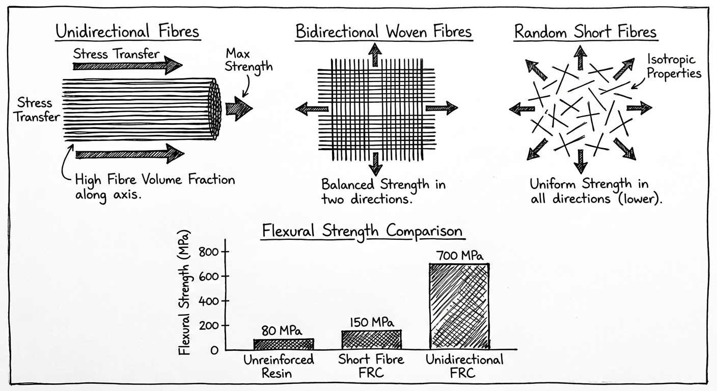
4.1 Unidirectional Fibres
- All fibres aligned parallel to one axis.
- Maximum strength and stiffness along the fibre axis.
- Anisotropic (strong in one direction only).
- Used in FRC FPDs where load is predictable and unidirectional.
- Flexural strength can reach 600-900 MPa (e.g., Stick Net/FibreKor).
4.2 Bidirectional / Woven Fibres
- Fibres woven at 0° and 90° (cross-ply) or at 0°/45°/90°.
- More isotropic than unidirectional.
- Lower peak strength than unidirectional but better in two planes.
- Used in periodontal splints, denture reinforcement.
4.3 Random Short Fibres (Chopped Fibre Mat)
- Short fibres randomly oriented throughout the matrix.
- Fully isotropic (properties equal in all directions).
- Weakest configuration.
- Used where complex shapes must be moulded (denture bases).
E_c = V_f × E_f + V_m × E_m
5. Mechanism of Reinforcement
- Stress transfer from matrix to fibre via the interfacial silane coupling agent layer.
- The stiff fibre resists deformation and bears the tensile stress.
- The matrix prevents crack propagation by distributing load.
- If the interfacial bond fails, the fibre debonds and pulls out of the matrix - this is the main failure mode.
- Crack deflection around fibres and fibre bridging of cracks absorbs significant fracture energy - this is why FRCs have much higher fracture toughness than unreinforced composites.
- Fibres shorter than a critical length (l_c) do not allow sufficient stress transfer and simply pull out.
- Fibres longer than l_c allow full stress transfer and fracture rather than pull out - this is the desired failure mode.
- l_c = (σ_f × d) / (2 × τ_i) where σ_f = fibre strength, d = fibre diameter, τ_i = interfacial shear strength.
6. Clinical Applications
6.1 Fixed Partial Dentures (FRC-FPD)
- Replace metal framework with FRC substructure.
- Technique: FRC ribbon/post (e.g., everStick C&B) embedded in pontic composite.
- Tooth preparation is minimal compared to conventional metal-ceramic FPD.
- Indicated for short-span (one missing tooth, 3-unit) FPDs in non-molar areas.
- Contraindicated for molar replacements (high occlusal load) and long spans.
6.2 Periodontal Splints
- Ribbond polyethylene or glass fibre ribbon placed in acid-etched channel/groove on lingual surfaces of mobile teeth and embedded in flowable composite.
- Semi-rigid splinting allows physiologic tooth movement while reducing hypermobility.
- Single appointment; reversible.
6.3 Orthodontic Retainers
- FRC or plain polyethylene fibre strips bonded to lingual surfaces as fixed retainers - alternative to metal wire retainers.
- Better aesthetics; can be repaired.
6.4 Endodontic Posts (FRC Posts)
- Glass fibre posts (e.g., DT Light Post, Luscent Anchors).
- Modulus of elasticity similar to dentine (18-40 GPa) - reduces risk of root fracture compared to rigid metal posts.
- Aesthetic (tooth-coloured); does not create grey shadow under ceramic crown.
- Adhesively cemented with resin cement + dual-cure bonding agent.
- Failure mode: adhesive failure (post debonding) rather than root fracture - preferred as it is reparable.
6.5 Denture Base Reinforcement
- Carbon fibre or woven glass fibre incorporated into PMMA denture base.
- Prevents midline fracture of complete dentures.
6.6 Direct Composite Restorations (Fibre-Reinforced)
- Short fibre-reinforced composite (e.g., everX Posterior) used as a bulk dentine-replacement layer under conventional composite.
- Short E-glass fibres (1-2 mm length) randomly oriented in Bis-GMA matrix.
- Significantly increases fracture toughness and resistance to crack propagation in large posterior restorations.
7. Advantages and Disadvantages
Advantages
- High strength-to-weight ratio compared to metals
- Tooth-coloured and aesthetic
- Modulus of elasticity can be tailored (e.g., FRC posts match dentine)
- Reduced need for tooth preparation vs metal frameworks
- Can be repaired with composite resin chairside
- Biocompatible (glass fibres are inert)
- No corrosion, no galvanism
- Radiolucent (glass fibre FPDs) - facilitates radiographic assessment of underlying tooth
Disadvantages
- Technique-sensitive: proper fibre-resin impregnation (wet-out) is critical
- Delamination can occur if fibres are not fully wetted
- Long-span FPDs have high failure rates (not indicated for molar replacement)
- Carbon fibres are opaque and aesthetically unacceptable in visible areas
- Cannot be relined easily (like metal frameworks)
- Marginal adaptation of FRC FPDs inferior to metal-ceramic
- Clinical longevity data still less extensive than conventional metal frameworks
- Polyethylene fibres (Ribbond) cannot be silanated - rely on mechanical interlocking only (weaker interfacial bond)
8. Failures and Management
| Failure Mode | Cause | Management |
|---|---|---|
| Fibre debonding | Inadequate silane / wet-out | Full replacement |
| Fracture at connector | Insufficient cross-section / span too long | Chairside repair with composite (temporary) → replacement |
| Decementation of FRC post | Moisture contamination, inadequate bonding | Recement or replace |
| Delamination (veneer fracture) | Surface composite worn away | Spot repair with composite |
| Periodontal splint debonding | Composite/enamel bond failure | Repolish, re-etch, rebond |
References
- Vallittu PK. Flexural properties of acrylic resin polymers reinforced with unidirectional and woven glass fibres. J Prosthet Dent. 1999;81(3):318-326.
- Freilich MA, Meiers JC, Duncan JP, Goldberg AJ. Fiber-Reinforced Composites in Clinical Dentistry. Quintessence Publishing; 2000.
- Behr M, Rosentritt M, Handel G. Fibre-reinforced composite crowns and FPDs: a clinical report. Int J Prosthodont. 2003;16(3):239-243.
- Lassila LV, Nohrström T, Vallittu PK. The influence of short-term water storage on the flexural properties of unidirectional glass fibre-reinforced composite. Biomaterials. 2002;23(10):2221-2229.
- Garoushi S, Vallittu PK, Lassila LV. Short glass fiber reinforced composite with a semi-interpenetrating polymer network matrix. Dent Mater. 2007;23(11):1356-1362.
- Garoushi S, Säilynoja E, Vallittu PK, Lassila LV. Physical properties and depth of cure of a new short fiber reinforced composite. Dent Mater. 2013;29(8):835-841. [everX Posterior]
- Ozcan M, Breuklander MH, Vallittu PK. Effect of length of glass fibre on the mechanical properties and repair strength of fibre-reinforced composite. J Oral Rehabil. 2005;32(1):29-35.
- van Heumen CC, Kreulen CM, Creugers NH. Clinical studies of fibre-reinforced resin-bonded fixed partial dentures: a systematic review. Eur J Oral Sci. 2009;117(1):1-6.
- Craig RG, Powers JM. Restorative Dental Materials. 11th ed. Mosby; 2002. Chapter on Polymers and Composites.
- Butterworth C, Ellakwa AE, Shortall A. Fibre-reinforced composites in restorative dentistry. Dent Update. 2003;30(6):300-306.
Exam tip (10-mark breakdown): 2 marks - introduction + composition; 2 marks - types of fibres; 2 marks - fibre architecture + mechanism; 3 marks - clinical applications; 1 mark - advantages/disadvantages. The FRC post and short-fibre composite (everX) are commonly asked distinguishing points.
Posterior composite restorations and composite resin as a post . For 25 marks . Give me contents to references
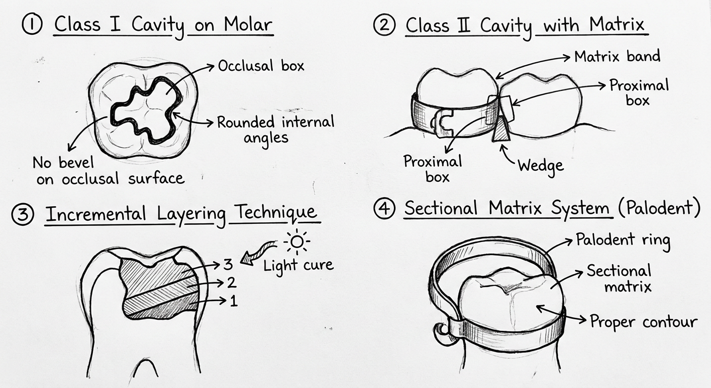
Hand-drawn dental diagram showing posterior composite restoration technique: (1) Class I cavity on molar - occlusal box with rounded internal angles, no bevel on occlusal surface, (2) Class II cavity showing proximal box with matrix band and wedge in place, (3) Incremental layering technique - oblique increments labeled 1,2,3 with light cure arrow, (4) Sectional matrix system (Palodent) with ring showing proper contour. Black ink educational sketch style, white background, neat handwritten labels.
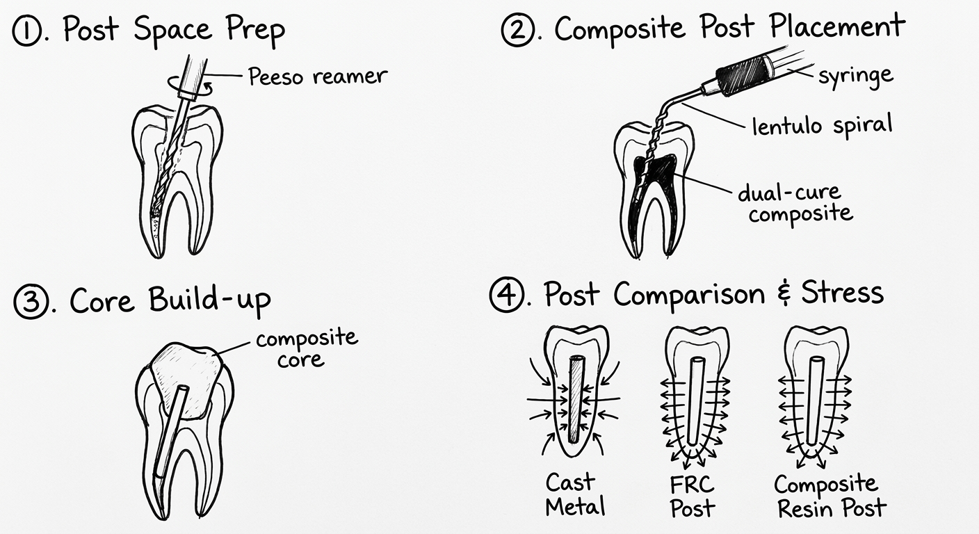
Hand-drawn dental diagram showing composite resin post and core: (1) Root canal cross section showing post space preparation with Peeso reamer, (2) Composite resin post placement - showing dual-cure composite injected into canal with lentulo spiral, (3) Core build-up with composite on top of post, (4) Comparison sketch of cast metal post vs FRC post vs composite resin post side by side showing stress distribution with arrows. Black ink educational sketch, white background, clear handwritten labels.
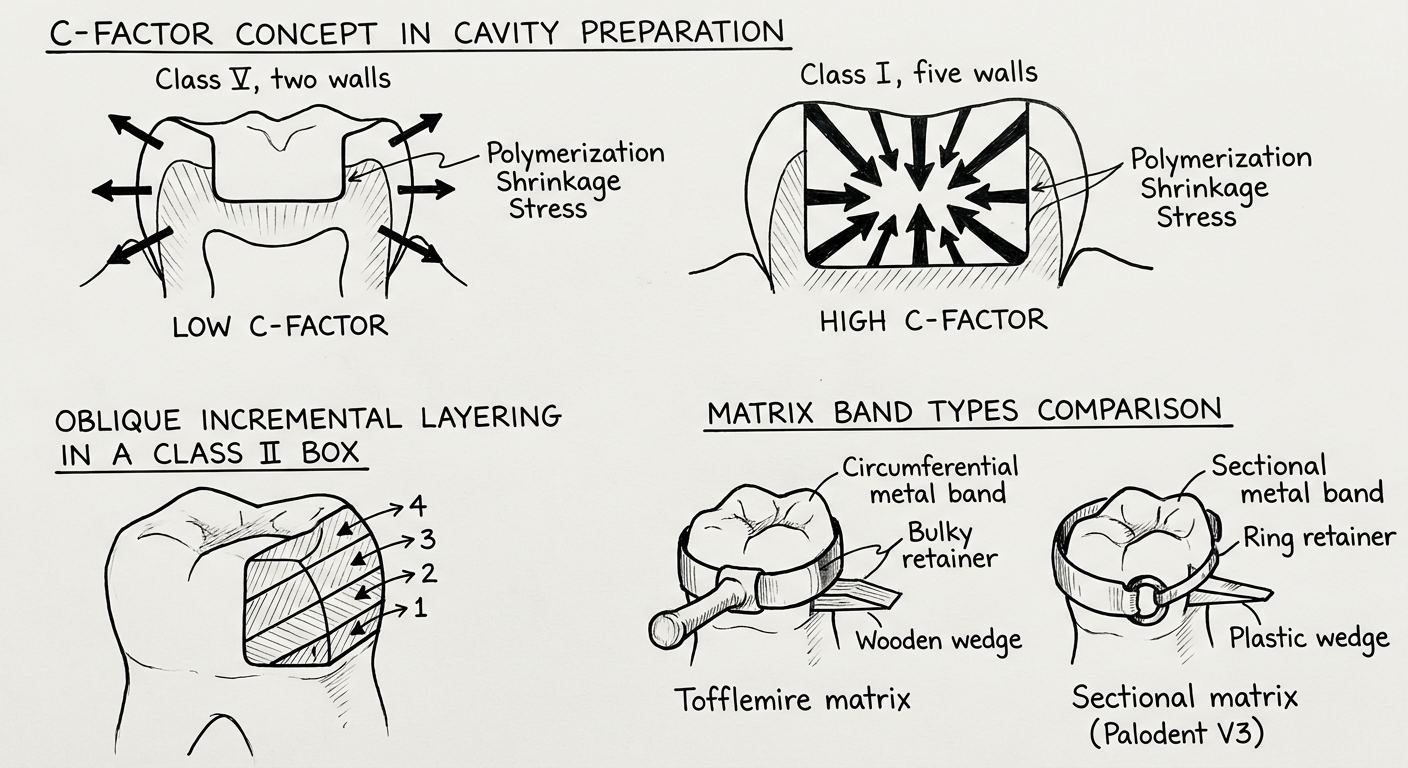
Hand-drawn dental diagram showing: (1) C-factor concept in cavity preparation - showing low C-factor (Class V, two walls) vs high C-factor (Class I, five walls) with stress arrows showing polymerization shrinkage stress, (2) Oblique incremental layering in a Class II box - increments labeled 1 through 4 each at oblique angle, (3) Matrix band types comparison - Tofflemire matrix vs sectional matrix (Palodent V3) with interdental wedge. Black ink educational sketch, white background, neat handwritten labels.
Posterior Composite Restorations and Composite Resin as a Post
Contents
-
Posterior Composite Restorations
- 1.1 Introduction and Historical Development
- 1.2 Indications and Contraindications
- 1.3 Cavity Design Principles
- 1.4 Materials: Composite Types Suitable for Posterior Use
- 1.5 Instruments and Accessories
- 1.6 Clinical Technique: Step-by-Step
- 1.7 Polymerization Shrinkage: Problem and Solutions
- 1.8 Matrix Systems for Class II Restorations
- 1.9 Finishing and Polishing
- 1.10 Wear and Clinical Longevity
- 1.11 Failures and Their Management
-
Composite Resin as a Post (Post and Core Build-up)
- 2.1 Introduction to Post-and-Core Systems
- 2.2 Composite Resin Post: Rationale and Materials
- 2.3 Indications and Contraindications
- 2.4 Post Space Preparation
- 2.5 Clinical Technique
- 2.6 Advantages and Disadvantages
- 2.7 Comparison with Other Post Systems
-
References
PART 1: POSTERIOR COMPOSITE RESTORATIONS
1.1 Introduction and Historical Development
- High polymerization shrinkage causing marginal gaps
- Poor wear resistance
- Difficulty achieving proximal contacts
- Inadequate depth of cure in deep cavities
- 1970s-80s: Introduction of hybrid composites with improved wear resistance (Lutz, Phillips)
- 1980s: Incremental placement technique to control polymerization shrinkage
- 1990s: Packable/condensable composites marketed for posterior use
- 2000s: Improved filler technology (nanofill, nanohybrid) with superior wear resistance
- 2010s: Bulk-fill composites (SDR, Tetric EvoCeram Bulk Fill, Filtek One Bulk Fill) allowing 4-5 mm increments
- 2020s: Short fibre-reinforced composites (everX Posterior) as dentine replacement layers
1.2 Indications and Contraindications
- Class I cavities (pit and fissure caries) in premolars and molars
- Class II cavities (involving proximal surface) - small to moderate size
- Replacement of failed amalgam restorations
- Cusp fractures (with adhesive buildup)
- Cracked tooth syndrome (with cuspal coverage composite)
- Patients requesting metal-free restorations
- Paediatric patients (primary molars)
- When minimal tooth preparation is desired
- Very large cavities involving > 2/3 of intercuspal width (consider indirect ceramic inlay/onlay)
- Heavy bruxism / parafunctional habits
- Inability to achieve adequate isolation (deep subgingival margins, poor patient cooperation)
- Gingival margin of Class II cavity extends far below CEJ (moisture contamination risk)
- Patients with known resin monomer allergy
1.3 Cavity Design Principles
- No bevels on occlusal margins (bevelled enamel rods are unsupported and fracture under occlusal load)
- Bevel is acceptable at proximal gingival margin (enamel rods run horizontally here - bevel exposes ends)
- Conservative outline form - remove only carious tooth structure; no need to extend to self-cleansing areas
- No undercuts needed - retention is purely adhesive
- Rounded internal line angles - reduces stress concentration
- Minimum depth: 1.5 mm (ensures adequate composite thickness)
- Isthmus width: Should not exceed 1/3 intercuspal width for posterior composites; > 1/2 requires cuspal coverage (indirect)
- Proximal box: Flared slightly (not parallel walls) for better light access and condensation
1.4 Materials: Composite Types for Posterior Use
| Type | Filler | Flexural Strength | Key Feature | Examples |
|---|---|---|---|---|
| Packable/Condensable | Large hybrid (1-10 µm) | 120-150 MPa | Firm consistency - easier proximal contact | SureFil, Alert |
| Nanohybrid | Nano + micro fillers | 120-180 MPa | Best balance of strength + aesthetics | Tetric EvoCeram, Ceram.x |
| Nanofill | 5-75 nm clusters | 100-140 MPa | High polish, good wear | Filtek Supreme Ultra |
| Bulk-Fill | Modified hybrid | 130-170 MPa | 4-5 mm single increment, low shrinkage stress | SDR, Tetric Bulk Fill, Filtek One |
| Short Fibre-Reinforced | E-glass fibres 1-2 mm | 195-230 MPa | Very high fracture toughness; used as base | everX Posterior |
| Flowable | Low filler % | 60-100 MPa | Cavity liner (stress-absorbing layer) | SDR base, Filtek Flow |
- Contain high molecular weight monomers and photoinitiator activators to allow full cure at depths > 2mm.
- Have lower elastic modulus (stress-relieving) or use shrinkage stress modulators (e.g., SDR's patented monomer with rotating groups).
- Two types:
- Flowable bulk-fill (SDR, Venus Bulk Fill): placed in 4-5 mm increments as base; must be capped with conventional composite for occlusal surface.
- Sculptable bulk-fill (Tetric EvoCeram Bulk Fill, Filtek One Bulk Fill): single increment fills entire cavity including occlusal surface.
1.5 Instruments and Accessories
- Composite instruments: Teflon-coated or titanium-nitride coated to prevent sticking (LM Arte series, Hu-Friedy)
- Light curing unit: LED lamp (440-480 nm range), minimum 1000 mW/cm² (high-intensity ≥ 1200 mW/cm² for bulk-fill)
- Matrix systems: (see Section 1.8)
- Wedges: Wooden or plastic interdental wedges for matrix adaptation
- Rubber dam: Mandatory for moisture control
- Shade guide: Vita Classical or Vita 3D-Master; select before isolation (dehydration lightens tooth)
1.6 Clinical Technique: Step-by-Step
- Check depth with probe.
- If pulp exposure risk: line with calcium hydroxide (Dycal) or MTA at deepest point only (indirect pulp capping). Do NOT line the entire cavity floor (reduces bond area).
- Proximal box: check that gingival floor is accessible and dry.
- Total-etch system OR self-etch system
- Total-etch: Apply 37% H₃PO₄ - enamel 30 sec, dentine 15 sec. Rinse thoroughly. Leave dentine slightly moist (wet bonding). Apply primer + bond. Light cure.
- Universal/Self-etch: Apply in scrubbing motion for 20 sec; air-thin; light cure.
- Bonding agent should be light-cured before composite (prevents monomer dilution of composite).
- Each increment ≤ 2 mm thickness (≤ 4-5 mm for approved bulk-fill)
- Oblique layering (diagonal increments touching only 2 walls at a time) - reduces C-factor and shrinkage stress
- Each increment: minimum 20 sec with ≥ 1000 mW/cm² LED.
- Cure from occlusal AND through buccal/lingual walls for deep boxes.
- Ensure light tip is as close to composite surface as possible (within 1 mm).
1.7 Polymerization Shrinkage: Problem and Solutions
- Marginal gaps → microleakage → secondary caries, postoperative sensitivity
- Internal stress → cuspal deflection → cusp fracture
- Loss of proximal contact
- Low C-factor (e.g., Class V - 2 bonded, 3 free) = LOW shrinkage stress
- High C-factor (e.g., Class I - 5 bonded, 1 free) = HIGH shrinkage stress
| Problem | Solution |
|---|---|
| High shrinkage | Use low-shrinkage composites (Silorane-based, bulk-fill) |
| High C-factor | Incremental placement (oblique); use flowable liner (elastic modulus ~1-5 GPa absorbs stress) |
| Deep cavity | Glass ionomer base ("Sandwich technique") - GIC lines deep dentine; composite builds occlusal |
| Marginal gaps | Proper bonding technique; light-cure in recommended increments |
| Post-op sensitivity | Adequate bonding; avoid over-etching dentine |
- Closed sandwich: GIC placed at deep dentine floor (subgingival margin); composite placed over GIC; GIC not exposed at margin. Combines GIC fluoride release + composite aesthetics.
- Open sandwich: GIC placed at gingival box floor and exposed at the gingival margin; composite placed over the occlusal portion. Allows GIC fluoride release at cervical margin.
1.8 Matrix Systems for Class II Posterior Composites
| System | Type | Advantages | Disadvantages |
|---|---|---|---|
| Tofflemire + matrix band | Circumferential | Low cost; widely available | Poor contour; flat contact |
| Sectional matrix (Palodent V3, Composi-Tight 3D) | Sectional with ring | Excellent contact contour and tightness; anatomically shaped | Higher cost; ring placement technique |
| Automatrix | Self-tightening band | No retainer needed; good for large restorations | Less control of contact |
- Adapt matrix band to gingival floor (prevent overhang)
- Create a small separation (spring-back after wedge removal ensures tight contact)
- Protect interdental papilla
1.9 Finishing and Polishing
- 12-blade carbide finishing burs (occlusal)
- Fine diamond burs
- Finishing discs (Sof-Lex, OptiDisc) - proximal surfaces
- Rubber polishing cups/points (Enhance, Astropol)
- Polishing paste (Prisma Gloss)
- Two-step finishing strips for proximal surfaces
1.10 Wear and Clinical Longevity
- Attrition - tooth-to-tooth contact
- Abrasion - mechanical (toothbrushing, food)
- Erosion - acid dissolution
- Fatigue wear - cyclic loading
- Well-placed posterior composite: AFR ~2-3% per year (similar to amalgam at 2%)
- Pallesen & Qvist (2003): 11-year survival rate of posterior composites = 82%
- Heintze & Rousson (2012) systematic review: Class II composite = similar longevity to amalgam in Class I and II cavities
1.11 Failures and Their Management
| Failure | Cause | Management |
|---|---|---|
| Secondary caries | Marginal leakage | Remove caries; repair or replace |
| Fracture (bulk) | Inadequate material thickness; occlusal overload | Repair with composite; consider indirect |
| Fracture (marginal) | Unsupported enamel; poor bond | Rebond margin or replace |
| Postoperative sensitivity | Incomplete resin tag formation; over-etching dentine | Desensitising agents; replace if persistent |
| Poor proximal contact | Matrix inadequacy | Polish if slight excess; replace if open contact |
| Staining | Inadequate polish; surface roughness | Polish; consider replacement if severe |
| Colour mismatch | Wrong shade | Spot veneer or replace |
PART 2: COMPOSITE RESIN AS A POST
2.1 Introduction to Post-and-Core Systems
- Retain the core (foundation for crown)
- Distribute functional loads along the root
- Post - extends into root canal space (1/2 to 2/3 root length)
- Core - replaces missing coronal tooth structure
- Crown - final restoration (usually ceramic or PFM crown)
2.2 Composite Resin Post: Rationale and Materials
- Composite resin core alone (when sufficient root canal walls remain to anchor core without a post - "coronal composite build-up")
- Composite injected into canal as a custom post - using the root canal as a mould; combined post-and-core in a single appointment
- Dual-cure composite resin (e.g., Rebilda DC, LuxaCore Dual, Clearfil DC Core Plus) - necessary because light cannot reach deep into root canal
- Some systems use fibre post + composite core (FRC post + composite) - this is the current standard; the composite forms the core
- True "composite-only" posts: older technique using injectable composite injected with a lentulo spiral or composite gun into the prepared canal
2.3 Indications and Contraindications
- Endodontically treated teeth with moderate coronal destruction (1-2 walls remaining)
- Teeth requiring immediate restoration (single-visit approach)
- Anterior and premolar teeth (lower occlusal loads)
- When cast post-and-core is not possible (economic, time constraints)
- Short roots or divergent canals (FRC post is better here but composite core is still used)
- When tooth is to be used as a bridge abutment (composite core with FRC post)
- Pediatric patients (primary and young permanent teeth - PMMA-based posts)
- Posterior teeth with heavy occlusal load (bruxism, molar - prefer cast post or FRC post)
- Very short root length (< 8 mm after apex resection)
- Root canal anatomy that does not allow adequate post length
- < 2mm of remaining radicular dentin (risk of root fracture with any post)
- Teeth without ferrule effect (< 2mm sound coronal dentine circumferentially - contraindication for any post-and-core; tooth is non-restorable)
- Wet canals / inadequate obturation seal
2.4 Post Space Preparation
- Remove gutta-percha from coronal 2/3 of canal using Peeso reamers or Gates Glidden burs (size 2-4) - rotary instruments at low speed, following canal direction.
- Leave minimum 4-5 mm of apical gutta-percha seal intact (to prevent apical microleakage).
- Post length should equal 1/2 to 2/3 of root length - minimum = crown length (≥ 8 mm).
- Post diameter should not exceed 1/3 of root diameter at any cross-section.
- Final shape: Slight taper matching canal anatomy; no sharp internal angles.
- Flush canal with EDTA + NaOCl; dry with paper points.
2.5 Clinical Technique for Composite Resin Post and Core
- Irrigate with 17% EDTA (removes smear layer) followed by 2.5-5% NaOCl. Final rinse with saline or distilled water.
- Dry with paper points (leave slightly moist for dentine bonding).
- Apply dual-cure bonding agent (e.g., Clearfil SE Bond, AdheSE) to canal walls using a micro-brush or endodontic syringe with long tip.
- Apply in multiple strokes to coat all canal walls.
- Avoid over-thinning (may leave insufficient bond).
- Light-cure accessible portion; rely on chemical cure for deep canal.
- Load dual-cure composite into a composite gun with intracanal tips (Centrix tip or lentulo spiral technique).
- Inject from apex of post space upward (tip seated at base; pull back while injecting - prevents voids).
- Fill canal to level of CEJ.
- Light cure from coronal access for 40-60 sec.
- Dual-cure component ensures chemical cure of deeper portions.
- While canal composite is setting but still slightly pliable (wet), build coronal core with additional dual-cure or regular composite.
- OR allow canal composite to fully set, then build core in separate increment.
- Carve and shape core to ideal preparation form for crown.
- Prepare core and remaining tooth structure for crown (full coverage crown).
- Ensure ferrule effect: 2 mm of sound natural coronal dentin circumferentially above crown margin, encircled by the crown - this is the most critical factor for long-term success (more important than post type).
- Bis-acryl or PMMA provisional crown while permanent crown is fabricated.
- Permanent ceramic or PFM crown cemented with glass ionomer, resin-modified GIC, or resin cement.
2.6 Advantages and Disadvantages of Composite Resin Post
- Single visit - post and core completed chairside in one appointment
- Conservative - no laboratory fabrication, no second visit
- No galvanism - no metal, no electrochemical reactions
- Aesthetic - tooth-coloured (especially with ceramic crown - no grey shadowing)
- Bondable to tooth and restorations - allows adhesive cementation
- Modifiable - can add composite if core is inadvertently reduced
- Lower cost vs cast gold post and core
- No stress concentration at post tip (as seen with rigid metal posts)
- Easy to remove/modify if re-treatment needed
- Lower retention than cast post (no mechanical interlock of custom cast design)
- Polymerization shrinkage within canal can create microleakage at dentine interface
- Moisture sensitivity during placement compromises bond
- Technique-sensitive - void-free injection into narrow canal is difficult
- Lower fracture resistance in molar teeth vs cast post-and-core
- Limited to coronal build-up strength - not suitable for > 3 missing walls in high-stress areas
- No proprioceptive flexibility advantage of FRC posts (which have modulus close to dentine)
2.7 Comparison of Post Systems
| Feature | Cast Metal Post | Prefabricated Metal Post | FRC Post + Composite Core | Composite Only (Resin Post) |
|---|---|---|---|---|
| Visits | 2 (lab) | 1-2 | 1-2 | 1 |
| Strength | Highest | High | Moderate-high | Moderate |
| Modulus (GPa) | 200 (steel) | 200 | 18-40 (near dentine) | 8-15 |
| Root fracture risk | High (rigid) | High | Low (flex with root) | Low-moderate |
| Aesthetics | Poor (metal shadow) | Poor | Excellent | Excellent |
| Removability | Difficult | Difficult | Moderate | Easiest |
| Cost | Highest | Moderate | Moderate | Lowest |
| Ferrule requirement | 2 mm mandatory | 2 mm mandatory | 2 mm mandatory | 2 mm mandatory |
| Repairability | Difficult | Difficult | Easy | Easy |
| Best indication | Long edentulous span abutment, molar, maximum destruction | Quick single visit, premolar | Gold standard for single-unit crowns | Anterior/premolar, limited destruction, economic |
- A crown that encircles 2 mm of sound coronal dentine like a "ferrule" on a barrel prevents root fracture and post-core dislodgement regardless of post type.
- Without ferrule: even the best post-and-core fails.
References
- Roberson TM, Heymann HO, Swift EJ. Sturdevant's Art and Science of Operative Dentistry. 5th ed. Mosby; 2006. Chapters 12-14 (Posterior Composite Restorations).
- Summitt JB, Robbins JW, Schwartz RS. Fundamentals of Operative Dentistry: A Contemporary Approach. 3rd ed. Quintessence; 2006.
- Lutz F, Phillips RW. A classification and evaluation of composite resin systems. J Prosthet Dent. 1983;50(4):480-488.
- Pallesen U, Qvist V. Composite resin fillings and inlays. An 11-year evaluation. Clin Oral Investig. 2003;7(2):71-79.
- Heintze SD, Rousson V. Clinical effectiveness of direct Class II restorations - a meta-analysis. J Adhes Dent. 2012;14(5):407-431.
- Lim BS, Ferracane JL, Condon JR, Adey JD. Effect of filler fraction and filler surface treatment on wear of microfilled composites. Dent Mater. 2002;18(1):1-11.
- Ferracane JL. Resin composite - state of the art. Dent Mater. 2011;27(1):29-38.
- Watts DC, Amer OM, Combe EC. Characteristics of visible-light-activated composite systems. Br Dent J. 1984;156(6):209-215.
- Garoushi S, Sailynoja E, Vallittu PK, Lassila LV. Physical properties and depth of cure of a new short fiber reinforced composite (everX Posterior). Dent Mater. 2013;29(8):835-841.
- Combe EC, Burke FJT, Douglas WH. Dental Biomaterials. Kluwer Academic Publishers; 1999.
- Schwartz RS, Robbins JW. Post placement and restoration of endodontically treated teeth: a literature review. J Endod. 2004;30(5):289-301.
- Dietschi D, Duc O, Krejci I, Sadan A. Biomechanical considerations for the restoration of endodontically treated teeth: a systematic review of the literature - Part 1 (composition and nature of the micro-structure). Quintessence Int. 2007;38(9):733-743.
- Bolla M, Muller-Bolla M, Abe I, et al. Root canal posts for the restoration of root filled teeth. Cochrane Database Syst Rev. 2007;(1):CD004623.
- Sorensen JA, Martinoff JT. Intracoronal reinforcement and coronal coverage: a study of endodontically treated teeth. J Prosthet Dent. 1984;51(6):780-784. [Ferrule Effect]
- Cheung W. A review of the management of endodontically treated teeth: post, core and the final restoration. J Am Dent Assoc. 2005;136(5):611-619.
Exam tip (25-mark distribution): Posterior composites ~14 marks - indications/contraindications (2), cavity design (2), technique/incremental placement (4), polymerization shrinkage and C-factor (2), matrix systems (2), wear/longevity (1), failures (1). Composite post ~11 marks - intro/rationale (1), indications/contraindications (2), technique (4), advantages/disadvantages (2), comparison table (2). Draw at least 2 diagrams (incremental layering + post system comparison) for full marks.