
Dynamic compression plate
dynamic compression plate DCP fracture fixation orthopaedic
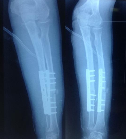
This diagnostic imaging consists of two postoperative X-ray views (anteroposterior and lateral) of a human forearm. The image demonstrates surgical internal fixation of both the radius and ulna. Two dynamic compression plates (DCP) are visible, secured to the mid-diaphyseal regions of both bones using multiple bicortical screws. A visible osteotomy or fracture gap is present in the mid-shaft of the radius, where the plate serves to maintain alignment and stability. The proximal radioulnar joint and the elbow joint appear well-aligned, and the distal radio-carpal joint is partially visible. The internal hardware is positioned to address a forearm deformity or non-union, facilitating bone healing through rigid internal fixation. This image is medically significant for orthopaedic education regarding the surgical management of diaphyseal forearm fractures or corrective osteotomies using plating techniques.
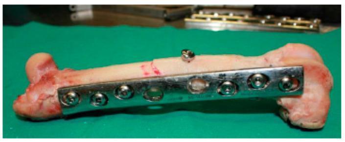
This clinical photograph displays an ex vivo femoral shaft undergoing internal fixation for a simple oblique fracture, serving as an educational example of orthopedic osteosynthesis. The primary stabilization is achieved using a shiny, metallic 8-hole Dynamic Compression Plate (DCP) contoured to the lateral aspect of the bone. The plate is secured with six bicortical screws positioned across the proximal and distal segments, acting in a neutralization function. Notably, an independent lag screw is placed perpendicularly across the fracture line to provide dynamic compression and enhance mechanical stability. The bone specimen exhibits a smooth cortical surface with visible reddish staining near the epiphyses, indicating the presence of vascularized tissue or residual soft matter. The arrangement demonstrates key principles of fracture management, including anatomical reduction and stable internal fixation to facilitate secondary bone healing. This image is relevant for surgical training and biomechanical study of plate-and-screw constructs in long bone fractures.
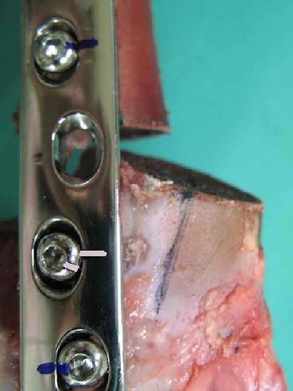
This clinical photograph displays a close-up of a Limited Contact Dynamic Compression Plate (LC-DCP) construct used in an orthopedic biomechanical study of femoral fracture fixation. The image illustrates a procedural failure analysis of an internal fixation system. A significant osteotomy gap is visible between the proximal and distal bone segments, showing asymmetrical widening at the cranial aspect and narrowing at the caudal aspect, indicating a cranial tilt and rotational displacement of the distal fragment. Metal screws are numbered for testing, with screw No. 5 specifically highlighting mechanical failure. The black marker lines on the screw head and the plate surface, which were originally aligned, show a clear deviation. This misalignment serves as visual confirmation of screw loosening and rotation within the plate hole during axial loading. The image is used to demonstrate the structural weakness of bone-plate constructs under compression and to identify signs of hardware migration in orthopedic surgery.
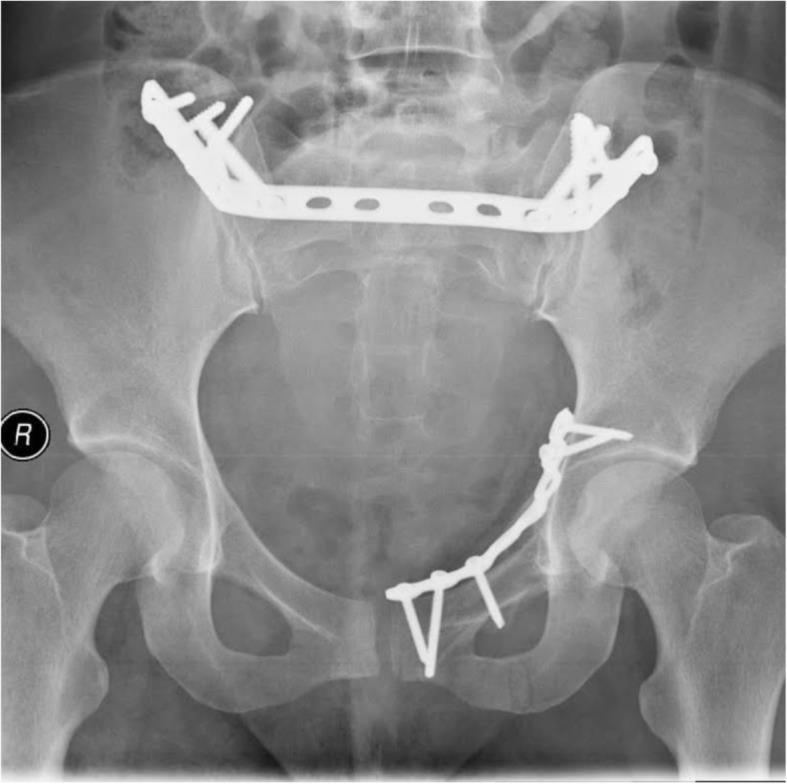
Anteroposterior (AP) pelvic X-ray radiography demonstrating postoperative internal fixation for a complex pelvic ring fracture. The image shows a combination of anterior and posterior stabilization using radiopaque metallic implants. Posteriorly, a transsacral dynamic compression plate (DCP) is visible, positioned horizontally across the sacrum and spanning the sacroiliac joints to bridge the posterior pelvic ring, secured with multiple screws into the iliac wings. Anteriorly, two separate plates are observed: a straight plate spans the superior aspect of the pubic symphysis for transverse stabilization, and a curvilinear reconstruction plate follows the contour of the left inferior pubic ramus, fixed with several orthopedic screws. The imaging highlights surgical management of pelvic instability through multi-planar internal fixation, ensuring the integrity of both the anterior and posterior arcs of the pelvic ring.
Dynamic Compression Plate (DCP)
Overview
Design Principles
The Oval/Inclined Screw Hole
- Load hole (compression end): The screw is inserted eccentrically toward the fracture end. As the spherical screw head slides down the inclined surface of the oval hole when tightened, the bone (and attached fragment) is displaced axially toward the fracture, generating interfragmentary compression.
- Neutral hole (neutral position): The screw is inserted centrally, resulting in no compression - used when simple screw anchorage without compression is desired.
DCP vs. LC-DCP (Limited Contact DCP)
| Feature | DCP | LC-DCP |
|---|---|---|
| Undersurface | Flat - broad contact with bone | Scalloped/undercut - reduces contact area |
| Periosteal blood supply | More compromise | Preserved (reduced contact) |
| Plate thickness | Uniform | Uniform |
| Screw hole | Original oval DCU | Improved combined compression/locking hole |
| Stiffness (bending) | Higher at fewer cortices | Slightly lower with fewer cortices |
| Stiffness (torsion) | Higher | Slightly lower |
| Current use | Largely superseded | More widely used |
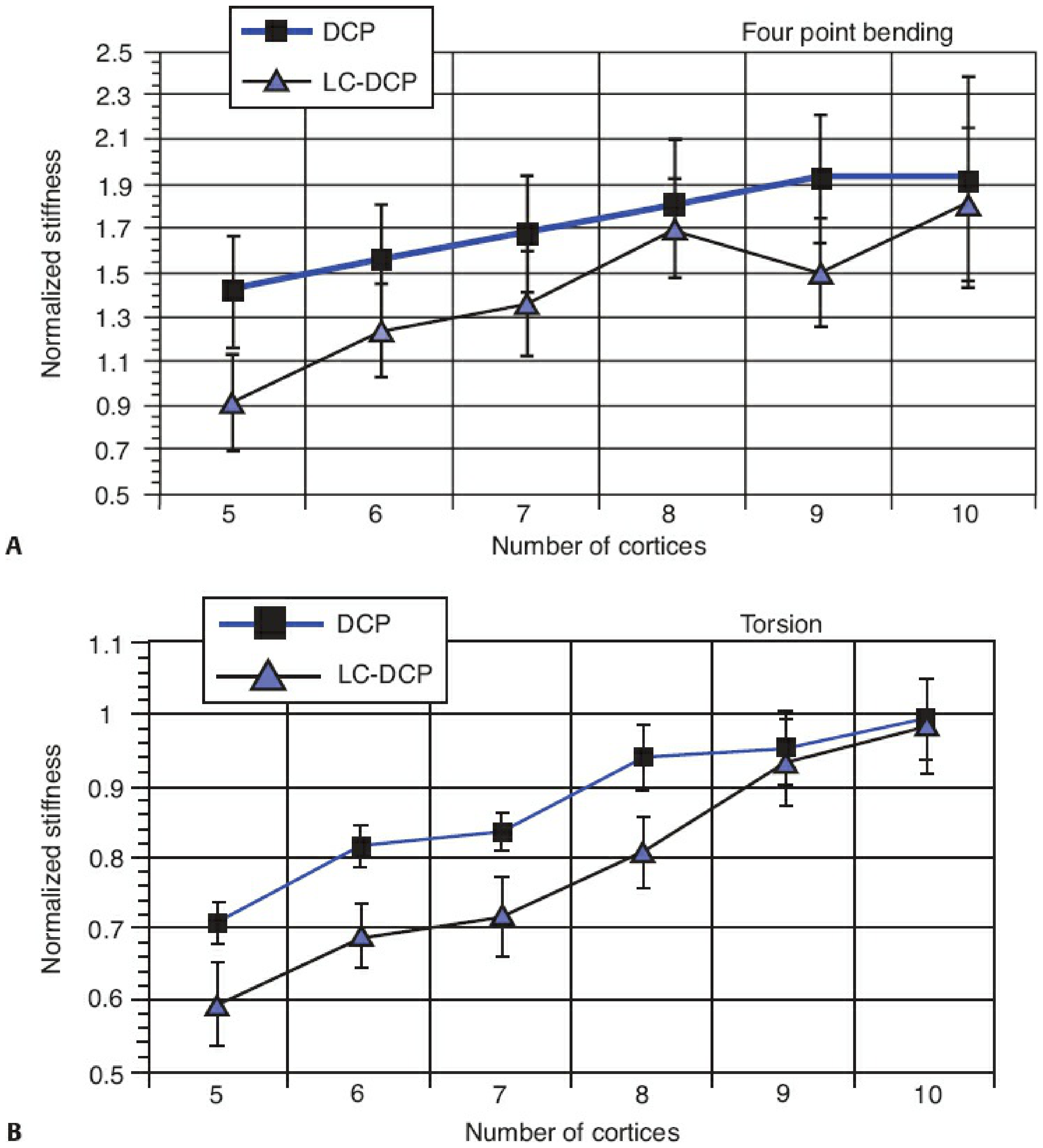
Modes of DCP Application
-
Compression mode - Screws placed eccentrically in the load position on both sides of the fracture; used for transverse or short oblique fractures. Generates axial interfragmentary compression.
-
Neutralization mode - Used after a lag screw has already compressed the fracture (e.g. spiral/oblique fractures). The plate neutralizes bending, torsional, and shear forces while the lag screw provides compression.
-
Buttress/Antiglide mode - Plate applied to resist shear/translational forces at partial articular fractures (e.g. distal radius, posterior malleolus, proximal tibia). An undercontoured plate compresses as the axillary screw is tightened.
-
Bridge plating mode - Used for highly comminuted fractures. The plate spans the comminuted zone without attempting anatomic reduction, preserving biology. This is a relative-stability construct allowing secondary (callus) healing. The DCP is less ideal here; longer plates (LCP) are preferred.
Sizes Available
| System | Plate Width | Screw Size | Typical Application |
|---|---|---|---|
| Large fragment | 4.5 mm | 4.5 mm cortical, 6.5 mm cancellous | Femur, tibia, humerus |
| Small fragment | 3.5 mm | 3.5 mm cortical, 4.0 mm cancellous | Radius, ulna, fibula, clavicle |
| Mini fragment | 2.7 mm | 2.7 mm cortical | Small bones, hand |
Biomechanical Principles
- Absolute stability - Required for primary bone healing. Achieved when interfragmentary strain is <2%. The DCP in compression mode achieves this.
- Plate placement on tension side - For eccentrically loaded bones (e.g. femur lateral side), the plate should be on the tension surface to act as a tension band.
- Over-contouring - For transverse diaphyseal fractures, the plate should be slightly over-contoured (bent a little away from bone at the fracture level) to prevent a gap opening on the far cortex when screws are tightened.
- Working length - The distance between the two innermost screws across the fracture. Longer working length = more elastic deformation, important in bridge plating.
- Plate failure - DCP plates fail in fatigue bending, especially if a gap exists on the cortex opposite the plate. The fracture site acts as a fulcrum, and cyclic loading eventually causes plate fracture. - Rockwood & Green's Fractures in Adults, p. 502-503
Technique Pearls
- Screw purchase: Non-locking screws grip bone by friction between plate undersurface and periosteum. Suboptimal insertional torque (10-15% less) can reduce fatigue life from 2.5 million to <1,000 loading cycles. - Rockwood & Green's, p. 501
- Minimum cortices: At least 6 cortices (3 screws) on each side of the fracture is the general rule for DCP constructs.
- Skip holes: Leaving a hole empty adjacent to the fracture reduces stress risers at that point in the plate.
- Articulated tensioning device: Can be used externally to generate additional compression before final screw tightening - seen commonly in femoral non-union repair.
Clinical Applications
- Forearm fractures (radius and ulna diaphysis) - 3.5 mm DCP is the standard
- Humeral shaft fractures - 4.5 mm or 3.5 mm DCP
- Tibial and femoral shaft fractures - 4.5 mm DCP (though IM nailing now preferred for most)
- Clavicle fractures - 3.5 mm DCP
- Distal humerus fractures - 3.5 mm DCP (lateral column)
- Corrective osteotomies - e.g. distal ulna with 3.5 mm DCP + 2.7 mm reconstruction plate
- Periprosthetic fractures - LC-DCP with cerclage cables
DCP vs. Locking Compression Plate (LCP)
- LCP in compression mode = functions like a DCP
- LCP with locking screws = fixed-angle construct, better for osteoporotic bone, metaphyseal regions, and periprosthetic fractures
- LCP locking construct fails when all screws fail simultaneously (not sequentially like conventional DCP screws)
Clinical Images