
Exlap than surgical procedure
exploratory laparotomy surgical procedure abdominal incision
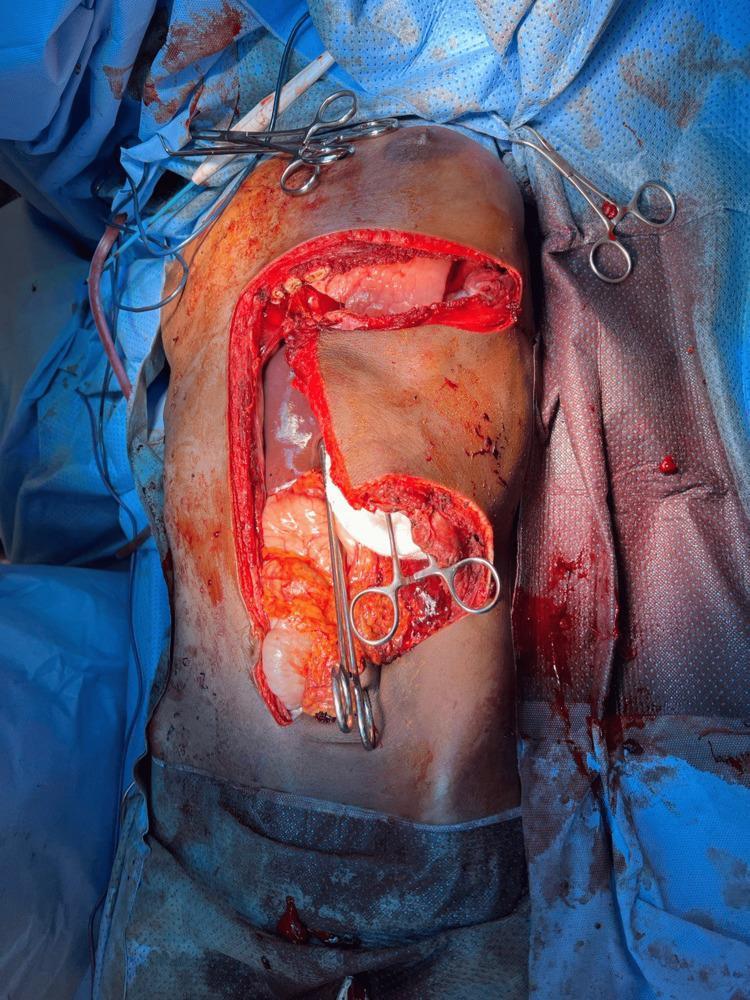
An intraoperative clinical photograph demonstrating an exploratory laparotomy using a thoracoabdominal approach. The image shows a large T-shaped surgical incision on the torso, consisting of a vertical midline abdominal incision and a horizontal left-sided transverse extension into the thoracic region. This wide exposure reveals the abdominal and lower thoracic cavities. Visible within the surgical field are various anatomical structures, including a dark red solid organ (likely the displaced spleen or liver) and a large, pale, lobulated soft tissue mass in the left upper quadrant. Several surgical instruments, including hemostatic clamps and retractors, are positioned along the skin edges and within the cavity to maintain surgical access. The surgical site is draped with blue sterile cloths, and there is evidence of minor hemorrhage consistent with an active procedure. This image illustrates the surgical access required for the resection of large retroperitoneal or diaphragmatic-herniating masses.
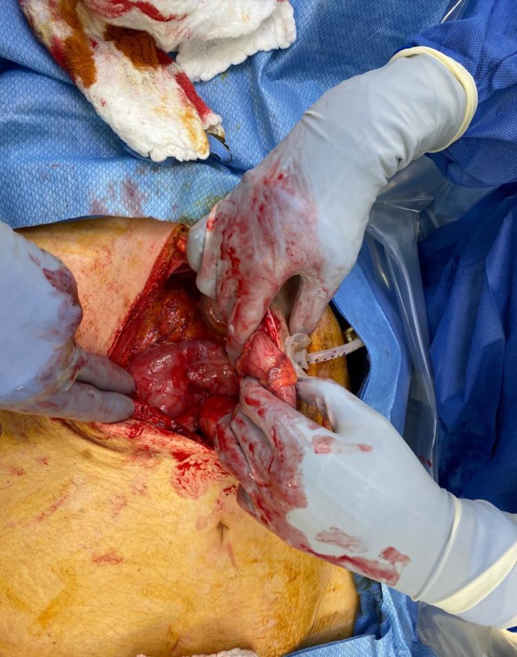
This clinical photograph displays an intraoperative view of an exploratory laparotomy. The surgical field reveals a midline abdominal incision through which internal organs, including the stomach and segments of the intestine, are visible. The tissues appear erythematous and glistening with serous and hemorrhagic fluid typical of an active surgical procedure. Surgeons' hands, wearing sterile gray nitrile or latex gloves stained with blood, are seen manipulating the abdominal viscera. A percutaneous endoscopic gastrostomy (PEG) tube is visible, emerging from the stomach/abdominal wall interface, representing the focus of the surgical intervention for malpositioning or replacement. The field is bordered by blue sterile surgical drapes, and a blood-stained surgical sponge is present in the upper left quadrant. This image illustrates the surgical management of a complication related to enteral access, specifically an intracolonic malposition of a PEG tube requiring open abdominal washout and visceral repair.
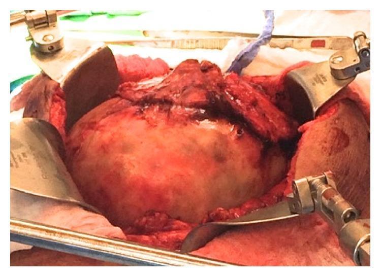
This clinical photograph captures a surgical procedure (exploratory laparotomy) showing a large, encapsulated intraperitoneal mass. The mass is exposed within the abdominal cavity, characterized by a tan-yellow hue and a smooth, dull capsular surface. It is densely adherent to the omentum, which is seen draped over the superior aspect of the lesion. Surrounding tissues exhibit signs of inflammation and potential hemorrhage, appearing erythematous and congested. Surgical exposure is maintained by multiple stainless steel retractors (part of a self-retaining retractor system) positioned along the margins of the abdominal incision. The image illustrates the intraoperative appearance of a giant abdominal pseudocyst, highlighting its anatomical relationship with the omentum and the surgical complexity involved in dissecting it from adherent abdominal structures.
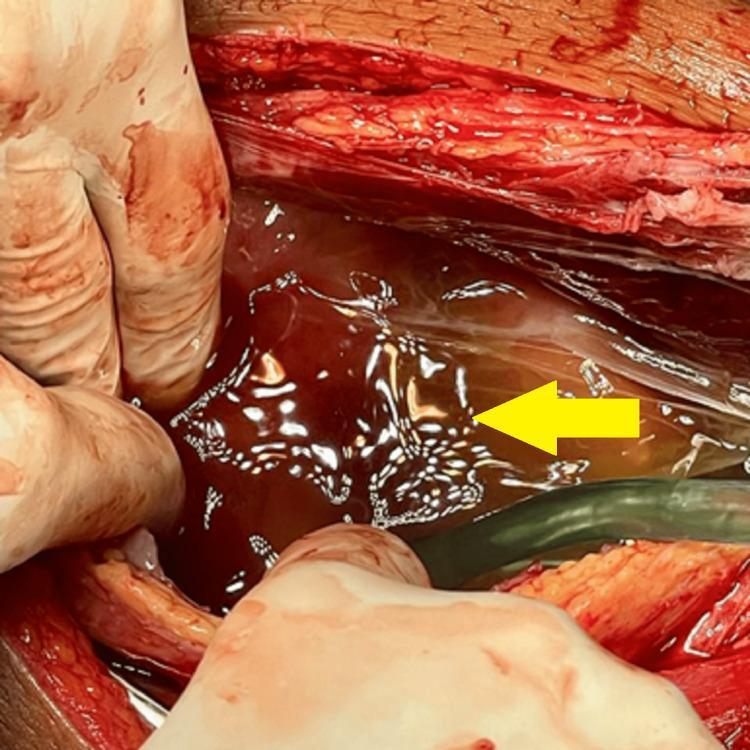
This intraoperative clinical photograph captures an exploratory laparotomy, a common surgical procedure for abdominal evaluation. The image displays an open surgical field characterized by a midline incision, revealing subcutaneous adipose tissue and skeletal muscle layers. A significant amount of translucent, amber-colored peritoneal fluid (ascites) is pooled within the abdominal cavity, as indicated by a yellow arrow. The fluid exhibits a glistening, reflective surface under the surgical lighting. To the left, gloved hands are visible, retracting the abdominal wall to facilitate visualization of the internal structures. A suction catheter or medical tube is positioned within the field, likely for the drainage of the ascitic fluid. The surrounding tissues appear erythematous and inflamed, which is consistent with the clinical context of suspected malignancy or advanced intra-abdominal pathology. This photograph serves as an educational tool for identifying ascites during surgical exploration and understanding the gross anatomical appearance of the peritoneal cavity in complex gynecological or oncological cases.
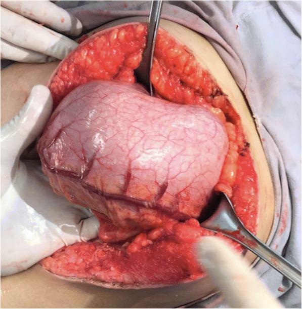
This clinical photograph captures an intraoperative view of an exploratory laparotomy, focusing on the anterior wall of the stomach. The organ is significantly distended, protruding through the abdominal incision. A hallmark feature shown is the prominent congestion and dilation of the gastroepiploic arteries across the serosal surface, indicating increased pressure or vascular compromise within the gastric chamber. Surgical retractors are positioned to maintain exposure of the operative field, revealing the subcutaneous adipose tissue and the underlying abdominal musculature. In the clinical context of the patient's presentation, this gastric distention is secondary to a large trichobezoar. The image serves as a teaching tool for recognizing macroscopic signs of gastric outlet obstruction and the surgical anatomy of the upper gastrointestinal tract during a gastrotomy procedure. It is relevant for medical students and surgical residents studying abdominal pathology, specifically bezoars and intestinal intussusception.
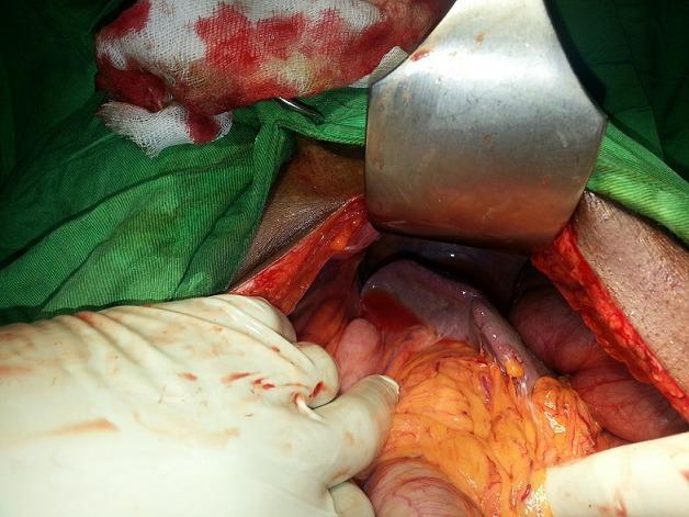
An intraoperative clinical photograph showing a surgical field during an exploratory laparotomy or abdominal procedure. The image displays the anatomical relationship between the spleen and the left colic flexure (splenic flexure) situated beneath the left diaphragmatic dome. A large metallic surgical retractor is positioned superiorly to provide exposure. Within the incision, lobulated orange-yellow adipose tissue (omentum) is prominent, adjacent to the reddish-purple smooth surface of the spleen and sections of the large intestine. A gloved hand is shown manipulating the visceral structures for inspection. The periphery includes green surgical drapes and blood-stained gauze sponges. This visual demonstrates the surgical anatomy of the upper left abdominal quadrant, relevant for cases involving pneumoperitoneum or diaphragmatic elevation of abdominal viscera.
Exploratory Laparotomy (Ex-Lap)
Definition
- Tintinalli's Emergency Medicine, A Comprehensive Study
Indications
Absolute Indications (Mandatory Exploration)
- Persistent hemodynamic instability despite resuscitation
- Peritonitis (signs of free peritoneal contamination)
- Abdominal wall disruption / peritoneal violation (e.g., evisceration)
- Extraluminal air (free air on X-ray or CT - indicates bowel perforation)
- Intra-abdominal or retroperitoneal air on plain radiograph or CT
- Transabdominal gunshot wounds (almost always have intra-abdominal injury)
Additional Indications
- Uncontrolled hemorrhage from solid organ injury
- Bowel obstruction not responding to conservative management
- Suspected ischemic bowel
- Abdominal compartment syndrome (ACS) requiring decompression
- Ruptured abdominal aortic aneurysm
- Gynecologic emergencies (ectopic pregnancy, ovarian torsion)
- Oncologic staging or biopsy when other methods fail
Pre-operative Setup
- Patient positioned supine, arms extended out ("crucifix" position)
- Prep and draping from chin to knees, table to table - this wide field allows extension of the incision or access to the chest or thighs if needed
- Urinary bladder drained (Foley catheter)
- Nasogastric tube placed
Surgical Technique: Step-by-Step
Step 1 - Incision
- Standard approach: Midline vertical incision (xiphoid to pubis)
- Quickest to make, quickest to close
- Allows maximum exposure of all abdominal organs
- Can be extended to the chest (sternum) or pelvis as needed
Step 2 - Entry into the Abdominal Cavity
- The linea alba is divided
- The peritoneum is entered carefully to avoid bowel injury
- On entry, any free blood, bile, or fecal matter is immediately noted
- Early hemorrhage control takes priority - any pulsatile or massive bleeding is addressed first
Step 3 - Initial Hemorrhage Control
- Rapid manual compression or packing of all four quadrants
- "Four-quadrant packing" - surgical packs placed into right upper quadrant (liver/right lobe), left upper quadrant (spleen), pelvis, and retroperitoneum
- Self-retaining retractors placed to maintain exposure
Step 4 - Systematic Exploration (the "Ex-Lap Survey")
| Structure | What to Look For |
|---|---|
| Liver | Lacerations, hematoma, bile leaks |
| Spleen | Lacerations, hilar injuries |
| Stomach | Anterior and posterior surfaces (requires opening the lesser sac) |
| Small bowel | Mesenteric hematoma, serosal tears, through-and-through perforations - run the entire bowel from Treitz to ileocecal valve |
| Colon | Perforations, mesenteric tears |
| Rectum | Pelvic hematoma, rectal injuries |
| Bladder | Extraperitoneal vs intraperitoneal rupture |
| Ureters | Visually or fluoroscopically inspected if injury not excluded |
| Great vessels | Aorta, IVC, mesenteric vessels |
| Diaphragm | Lacerations (especially in penetrating trauma) |
| Retroperitoneum | Zone I (midline - vascular), Zone II (perinephric), Zone III (pelvic) hematomas |
"The basic principles of the trauma laparotomy include prepping and draping from chin to knees and from table to table, rapid entry into the abdominal cavity, early control of bleeding, temporary control of contamination, exploration of the entire intra-abdominal cavity, and finally either definitive repair of injured structures or a damage control operation with temporary abdominal closure."
- Mulholland and Greenfield's Surgery, 7e
Step 5 - Definitive Repair OR Damage Control Decision
- Bowel resection and anastomosis
- Splenorrhaphy or splenectomy
- Hepatorrhaphy
- Vascular repair
- Focus only on hemorrhage control and temporary contamination control
- Pack the abdomen and close temporarily
- Transfer to ICU for resuscitation and correction of the "lethal triad": acidosis, coagulopathy, hypothermia
- Return to OR within 24-48 hours for definitive repair and fascial closure
Damage Control Laparotomy (DCL) - Key Concept
- Uncontrolled acidosis
- Coagulopathy
- Hypothermia
- Control bleeding and contamination (abbreviated operation, ~30-60 min)
- Temporary abdominal closure (TAC) - various techniques available
- ICU resuscitation with blood products (whole blood or balanced component therapy, NOT crystalloids)
- Return to OR for definitive repair when physiology is corrected
Temporary Abdominal Closure (TAC)
- Bogota bag (sterile IV bag sutured to fascia edges)
- Vacuum-assisted wound closure (negative pressure wound therapy) - most common modern technique
- Wittmann patch (Velcro-type device that allows progressive closure)
Abdominal Compartment Syndrome (ACS) and Decompressive Laparotomy
- Grade III: IAP 21-25 mmHg
- Grade IV: IAP ≥25 mmHg
- Cardiac failure (reduced venous return)
- Pulmonary compromise (restricted diaphragm excursion)
- Oliguria / renal failure (renal vein compression)
Closure
- Fascia: Closed with mass closure technique using looped PDS or Prolene (running suture)
- Subcutaneous tissue: Irrigated
- Skin: Closed primarily (if clean) or left open (if contaminated) for delayed primary closure
Complications
| Complication | Details |
|---|---|
| Surgical site infection | Most common, especially in contaminated cases |
| Anastomotic leak | Risk especially in emergency bowel resection |
| Enterocutaneous fistula | Particularly after damage control |
| Incisional hernia | Long-term complication of midline incision |
| Ileus | Expected; paralytic ileus 3-5 days post-op |
| Adhesions | Can cause future small bowel obstruction |
| Abdominal compartment syndrome | After massive resuscitation |
| Wound dehiscence | Especially in malnourished or septic patients |
Key Clinical Pearls
- Penetrating abdominal gunshot wounds - mandatory exploration in most cases
- Stab wounds - selective exploration; local wound exploration can determine if peritoneum was violated before committing to full laparotomy
- Blunt trauma - FAST exam (Focused Assessment with Sonography in Trauma) and CT guide the decision; hemodynamically stable patients can often be managed non-operatively
- The Eastern Association for the Surgery of Trauma (EAST) and Western Trauma Association (WTA) recommend non-operative management as the standard of care for hemodynamically stable blunt hepatic and splenic injuries, irrespective of grade
- Nontherapeutic laparotomy rates are an important quality metric - mandatory exploration of all stab wounds yielded unacceptably high non-therapeutic rates
Parts of xray
parts of X-ray machine components diagram
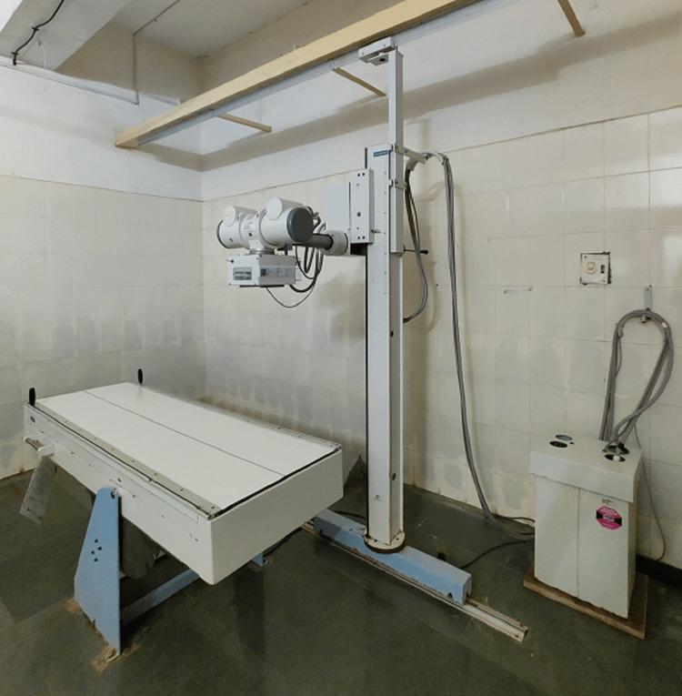
A clinical photograph of a stationary diagnostic X-ray machine within a medical facility. The equipment comprises three primary components: a radiographic examination table, a ceiling-and-floor mounted X-ray tube assembly, and a generator control unit. The examination table is a flat, white, rectangular platform supported by a blue-framed pedestal base. The X-ray source (tube housing and collimator) is mounted on a vertical support column that travels along a floor-mounted rail and a ceiling track, allowing for longitudinal positioning over the patient. Thick insulated high-voltage cables connect the X-ray tube to a floor-standing generator cabinet. The setting features clinical infrastructure including white-tiled walls and a dark, non-porous linoleum floor. This visual serves to illustrate the fundamental hardware configuration used in conventional radiography for skeletal and thoracic diagnostic imaging.
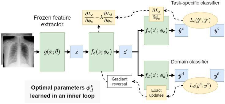
A machine learning flowchart detailing a feature disentanglement modeling approach for chest X-ray (CXR) analysis. The diagram begins with a standard posteroanterior (PA) chest X-ray input, illustrating the lung fields, rib cage, and mediastinal structures. This image is processed through a 'Frozen feature extractor' g(x; θ) to create an initial embedding (z), followed by a second feature extractor fe(z; φe) to produce a compressed representation (z'). The architecture then splits into two distinct pathways: a 'Task-specific classifier' fc(z'; φc) that predicts clinical class labels (e.g., normal, pneumonia, or COVID-19) and a 'Domain classifier' fd(z'; φd) that predicts the source dataset or domain. A 'Gradient reversal' layer is integrated between the secondary feature extractor and the domain classifier to ensure learned representations are predictive of pathology but invariant to source domain bias. This approach aims to improve the generalizability of diagnostic algorithms in radiology by removing non-clinical site-specific features.
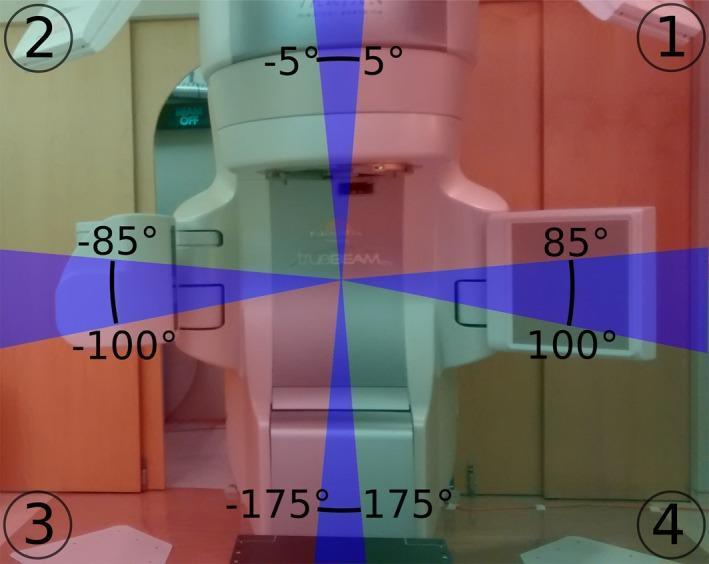
An educational diagram superimposed on a clinical photograph illustrating the geometry of a room-mounted dual X-ray imaging system used in radiotherapy. The image identifies four primary components: X-ray detectors labeled '1' and '2' in the upper corners, and X-ray sources labeled '3' and '4' in the lower corners. Colored shaded regions mapped over the central treatment gantry indicate imaging capabilities relative to gantry rotation angles. Blue shaded areas (centered around -175° to 175°, -5° to 5°, -85° to -100°, and 85° to 100°) represent sectors where stereoscopic imaging is available. Red shaded regions indicate monoscopic imaging capability using the right-side X-ray tube, while green shaded regions indicate monoscopic imaging using the left-side tube. This visualization demonstrates how the rotating treatment gantry periodically obstructs the X-ray pathways, necessitating a switch between stereoscopic and monoscopic target tracking during Volumetric Modulated Arc Therapy (VMAT).
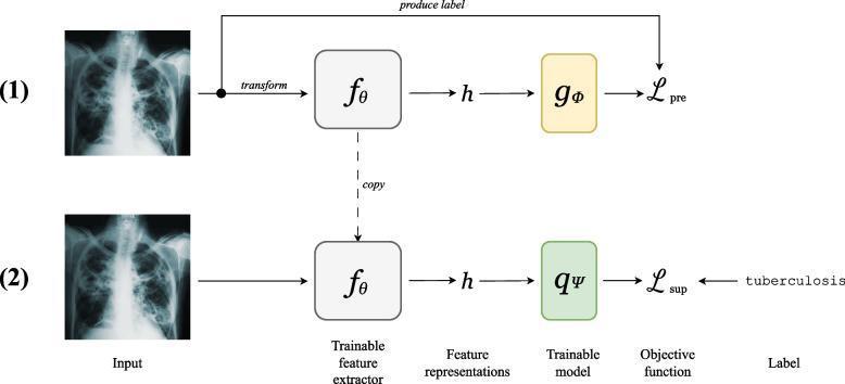
A two-stage machine learning flowchart illustrating a Self-Supervised Learning (SSL) workflow applied to chest X-ray classification. The diagram is divided into two phases: (1) Self-supervised pretraining and (2) Supervised fine-tuning. In the first phase, a chest X-ray exhibiting bilateral reticular opacities and areas of consolidation is used as input. It undergoes a transformation and is processed by a trainable feature extractor (f-theta) to produce feature representations (h), which are then sent to a trainable model (g-phi) to minimize a pretext objective function. In the second phase, the learned feature extractor parameters are copied to a new model. A similar chest X-ray input is processed to produce representations (h) for a different trainable model (q-psi). This stage incorporates specific diagnostic labels, such as 'tuberculosis', to minimize a supervised objective function (L-sup). The diagram highlights the educational concept of using unlabelled medical imaging data to learn useful anatomical and pathological features before applying them to specific clinical diagnostic tasks.
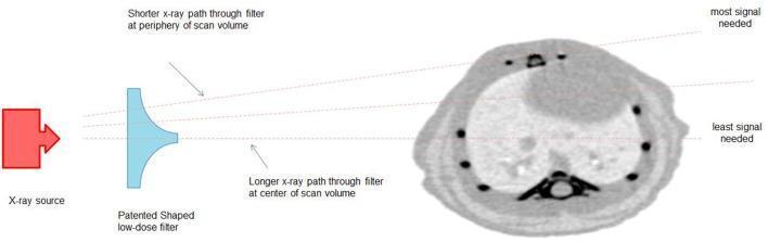
A technical diagram illustrating a novel X-ray beam shaper system designed for low-dose computed tomography (CT). The components include an X-ray source emitting a beam toward a 'Patented Shaped low-dose filter' (a bow-tie-like beam shaper), which then passes through to a representative axial scan image of a small animal. The filter is physically designed with a thicker central section and thinner peripheral edges. Annotations explain that this shape results in a 'longer X-ray path through filter at center,' providing higher attenuation where the scan volume requires the 'least signal needed.' Conversely, the 'shorter X-ray path through filter at periphery' allows more photons to pass through where the 'most signal' is required for accurate image reconstruction. This beam modulation strategy is intended to reduce radiation dose by 2-5 times by minimizing redundant photon flux in the center of the imaging field. The image falls under preclinical radiology and diagnostic physics, focusing on dose optimization and beam hardening principles.
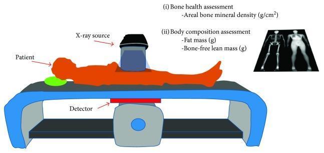
This medical illustration depicts a Dual-Energy X-ray Absorptiometry (DEXA) scanner setup and its clinical applications. The central diagram shows a patient in the supine position on a scanning table. Key instrumental components are identified: an X-ray source positioned above the patient and a detector located directly beneath the table, illustrating the transmission of X-ray beams through the body. Textual annotations outline the dual utility of the modality: (i) Bone health assessment, which measures areal bone mineral density (g/cm²), and (ii) Body composition assessment, which quantifies fat mass (g) and bone-free lean mass (g). To the right, representative diagnostic images from a DEXA scan are displayed, including a skeletal view and a soft tissue body composition map. This visual serves as an educational summary of how DEXA scans utilize high- and low-energy X-ray beams to accurately differentiate and measure various body tissues for metabolic and musculoskeletal health evaluations.
chest X-ray anatomy labeled parts interpretation
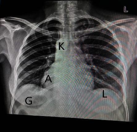
A posteroanterior (PA) chest X-ray demonstrating situs inversus totalis, a congenital condition where the major visceral organs are reversed from their normal positions. The imaging modality clearly shows dextrocardia, with the cardiac apex (A) and the aortic knuckle (K) situated in the right hemithorax. In the subdiaphragmatic region, there is a complete transposition of abdominal viscera: the gastric bubble (G) is located in the right upper quadrant, while the radiopaque liver shadow (L) is positioned in the left upper quadrant. The anatomical landmarks are labeled to highlight this mirror-image arrangement relative to typical human anatomy. This diagnostic image is intended for medical education regarding congenital anomalies, radiological identification of situs syndromes, and clinical interpretation of chest radiographs in patients with dextrocardia.
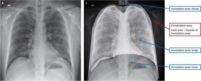
This figure presents a comparative study of X-ray radiography using an Explainable Interactive Machine Learning (XIL) optimization strategy. The visual is divided into two panels: a standard grayscale chest X-ray on the left and an annotated version on the right. The original X-ray displays typical thoracic anatomy, including the rib cage, lung parenchyma, and mediastinum. The annotated image on the right illustrates the implementation of binary masks used to guide machine learning models. Three specific 'Annotation areas' are labeled with blue arrows: the throat (superior aspect, upper airway), the lungs (bilateral thoracic cavity), and the torso (inferior aspect, abdominal region). These highlighted areas represent the relevant anatomical features the model should utilize for diagnostic prediction. Conversely, the regions outside these masks are darkened, identified by a red arrow as 'Penalization areas.' These dark zones signify regions the model is penalized for focusing on, effectively masking potential confounders such as skeletal maturity markers or external imaging artifacts. This approach demonstrates how human-in-the-loop expert knowledge can refine algorithmic focus in medical imaging.
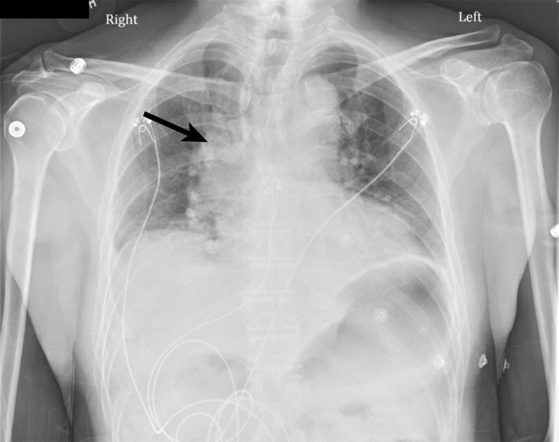
This diagnostic image is a posteroanterior (PA) chest X-ray illustrating thoracic anatomy and specific pathological findings. The primary focus is indicated by a black arrow pointing to significant right hilar fullness, characterized by increased density and enlargement of the right hilar region compared to the left. The lung fields demonstrate bibasal opacities consistent with atelectasis, more prominent at the lung bases bilaterally. Anatomical structures including the clavicles, ribs, humeri, and cardiac silhouette are visible. Multiple medical artifacts are present, specifically several EKG leads and associated wires overlaying the chest and abdominal regions, along with a possible central venous catheter. The image serves as a clinical example of hilar prominence and pulmonary atelectasis within the context of emergency or acute care medicine. The positioning and presence of monitoring equipment suggest an inpatient or acute clinical setting. This visual material is intended for intermediate medical education regarding the interpretation of thoracic radiographs and identifying hilar abnormalities.
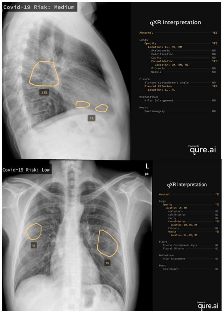
This composite diagnostic image features two examples of AI-assisted chest X-ray (CXR) interpretation using the qure.ai qXR algorithm. The top panel displays a lateral CXR labeled 'Covid-19 Risk: Medium', showing opacities and consolidations highlighted by orange contour overlays with percentage quantifications (23% and 4%). Corresponding structured data indicates abnormalities in the left lower (LL), right upper (RU), and right middle (RM) lung fields, alongside pleural effusions. The bottom panel displays a posterior-anterior (PA) CXR labeled 'Covid-19 Risk: Low', featuring multifocal opacities and nodules in the left middle (LM), right upper (RU), and right middle (RM) regions, with 4% and 8% lung involvement marked. Both panels include a 'qXR Interpretation' checklist that categorizes findings across four domains: Lungs (opacity, consolidation, nodules), Pleura (effusion, blunted angles), Mediastinum (hilar enlargement), and Heart (cardiomegaly). This comparison illustrates how deep learning algorithms quantify disease severity, such as COVID-19 pneumonia, by identifying specific radiological markers and calculating risk scores to support clinical triage.
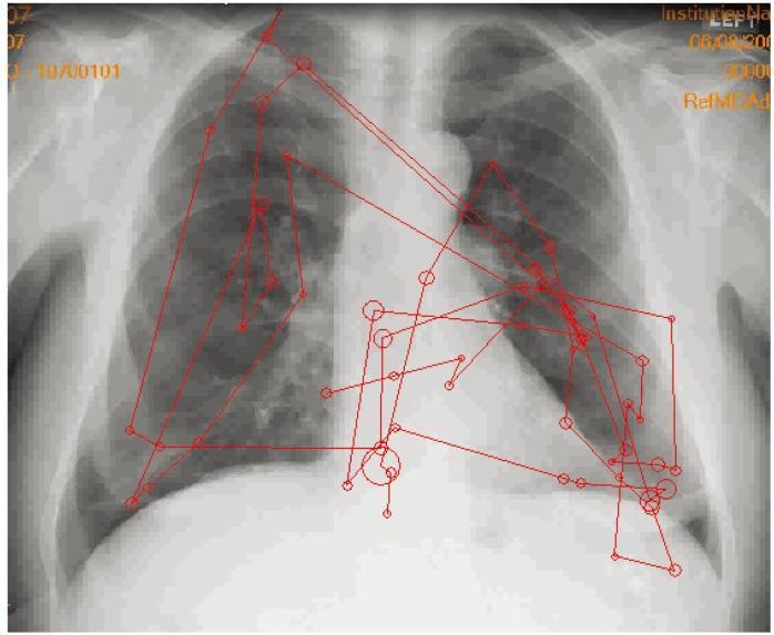
This diagnostic image is a posterior-anterior (PA) chest radiograph featuring a red eye-tracking overlay that illustrates a radiologist's visual search pattern. The underlying X-ray shows standard thoracic anatomy, including the lungs, heart silhouette, mediastinum, and rib cage. The red overlay consists of circles of varying diameters, representing 'fixations' where the viewer's foveal vision focused; larger circles indicate longer dwell times on specific anatomical features or suspicious findings. These circles are interconnected by straight red lines, which represent 'saccades' or the rapid eye movements between fixations. The scanpath demonstrates a systematic review, with clusters of fixations centered on the hila, lung fields, and the cardiac borders. This infographic serves as a pedagogical tool in radiology education to demonstrate perceptual strategies, the importance of foveal vision in detecting fine details, and the difference between expert and novice image interpretation patterns. It highlights the cognitive process involved in diagnostic image analysis.
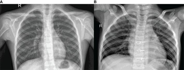
This comparative diagnostic image features two posterior-anterior (PA) chest radiographs (labeled A and B) illustrating the radiological differences between healthy and diseased lungs. Image A represents a healthy chest X-ray, demonstrating clear, radiolucent (dark) lung fields with normal vascular markings. The cardiac silhouette, costophrenic angles, and diaphragmatic contours are sharply defined. Image B shows a chest X-ray characteristic of pneumonia, exhibiting diffuse, multifocal opacities and patchy infiltrates throughout the lung parenchyma, particularly in the middle and lower zones. These findings represent pulmonary consolidation and fluid accumulation. A distinctive feature in Image B is the presence of radio-opaque surgical staples along the midline of the thoracic spine, likely representing prior surgical intervention. Both images display standard thoracic anatomy, including the rib cage, clavicles, humeri, and vertebral column. This visual comparison is used in medical education to teach the identification of pulmonary infections and the recognition of radiological signs such as infiltrates and obscured heart borders.
normal chest X-ray labeled anatomy trachea carina hilum heart costophrenic angle diaphragm
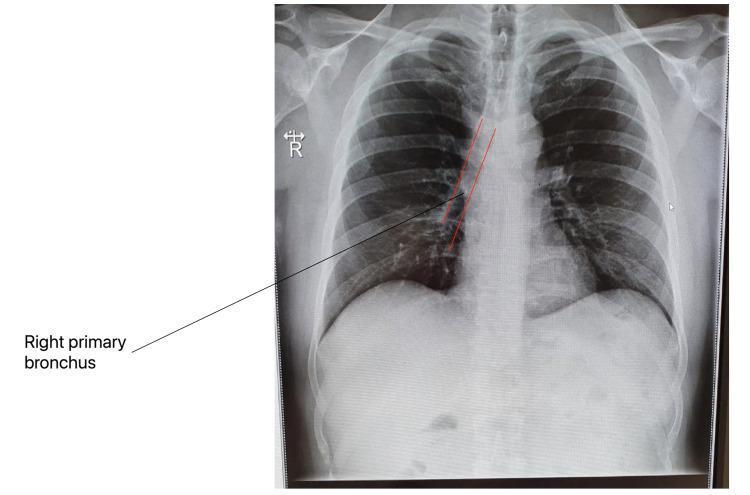
This diagnostic image is a posteroanterior (PA) chest X-ray illustrating normal thoracic anatomy. The radiographic view displays a clear tracheobronchial tree, with specific red line annotations and a pointer identifying the right primary bronchus as it descends from the carina into the right lung hilum. The lung parenchyma appears radiolucent and bilaterally symmetrical without evidence of consolidations, masses, or pleural effusions. Key anatomical landmarks visible include the heart and mediastinal borders, the diaphragm with sharp costophrenic angles, and the bony structures of the rib cage, clavicles, and thoracic vertebrae. This visual serves as an educational baseline for clinical radiology, demonstrating the expected vertical orientation of the right mainstem bronchus relative to the left, which is significant in the study of foreign body aspiration and pulmonary infection pathways, such as those seen in COVID-19 progression.
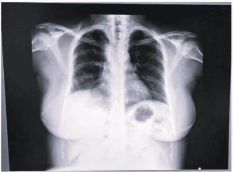
This diagnostic image is a posteroanterior (PA) view chest X-ray. The primary finding is a large, well-circumscribed, rounded, and homogenous opacity located in the right upper hemithorax. The opacity demonstrates significant mass effect, resulting in a notable lateral deviation of the trachea toward the left side, particularly above the level of the carina. The medial border of the mass abuts the mediastinum, causing widening and partially obscuring the superior right heart border. The right hemi-diaphragm is difficult to distinguish due to the density of the mass. In contrast, the left lung field appears clear with normal bronchovascular markings, and the left costophrenic angle is sharp. The cardiac silhouette, where visible, is within normal limits for size. This radiograph illustrates key educational concepts regarding mediastinal masses, such as bronchogenic cysts, and their secondary effects on airway patency and anatomical displacement. It is appropriate for medical students and radiology residents studying thoracic pathology and the interpretation of obstructive mass lesions.
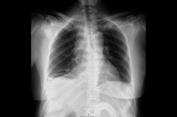
A posteroanterior (PA) thoracic X-ray displaying the lungs, heart, and bony structures of the chest. The primary diagnostic finding is a blunted right costophrenic angle with a faint band of opacification layering superiorly and laterally along the chest wall, consistent with a small, free-flowing right-sided pleural effusion. The left costophrenic angle remains sharp and clear. The bilateral lung fields are otherwise largely lucent without evidence of focal consolidation, masses, or interstitial edema. The bronchovascular markings are normal in distribution. The mediastinal silhouette is midline and of normal width, and the cardiac silhouette shows a normal size and configuration for this projection. The trachea is centrally located, and the visualized skeletal structures, including the ribs and clavicles, appear intact. This diagnostic image is used in medical education to illustrate the subtle early radiographic signs of pleural fluid accumulation, which in this clinical context was the initial manifestation of an underlying pleural malignancy.
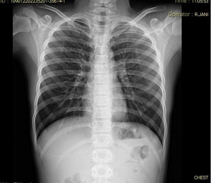
This diagnostic image is a posterior-anterior (PA) chest X-ray of a pediatric patient, demonstrating normal cardiopulmonary and skeletal anatomy. The radiograph shows clear lung fields without evidence of focal consolidations, opacities, or pleural effusions. The bronchovascular markings are within normal limits, extending from the hilar regions. The cardiomediastinal silhouette is normal in size and contour, with a clearly defined heart border and visible trachea positioned centrally. The diaphragm appears smooth and dome-shaped bilaterally, with clear costophrenic angles. Skeletal structures, including the clavicles, ribs, scapulae, and the thoracic vertebral column, appear intact without evidence of acute fractures, dislocations, or degenerative changes. The image serves as a clinical baseline for a normal chest examination in a pediatric surgical context, specifically used here to rule out respiratory involvement in a patient with abdominal symptoms.
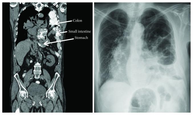
This composite diagnostic image features a side-by-side comparison of a coronal CT scan and a posterior-anterior (PA) chest X-ray illustrating a massive left-sided traumatic diaphragmatic hernia. The coronal CT image (left) uses labeled arrows to demonstrate the displacement of abdominal viscera into the thoracic cavity, including the stomach, small intestine, and colon. The diaphragm is clearly ruptured on the left side, while the liver remains in its normal position in the right upper quadrant. The chest X-ray (right) reveals multiple loops of air-filled bowel occupying the left hemithorax, resulting in significant compression of the left lung and a contralateral mediastinal shift of the heart and trachea toward the right. There is an associated obscuration of the left costophrenic angle and hemidiaphragm silhouette. These images serve as classic clinical examples of acute respiratory insufficiency caused by visceral herniation following diaphragmatic injury, highlighting the importance of multimodality imaging in diagnosing thoracic trauma.
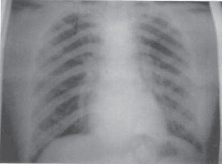
A posterior-anterior (PA) view chest X-ray illustrating normal thoracic anatomy. The radiographic image shows clear and well-aerated bilateral lung fields with no visible pulmonary opacities, infiltrates, or masses. The cardiac silhouette is of normal size and position within the mediastinum, and the trachea is observed at the midline. Both costophrenic angles are sharp, and the diaphragmatic domes are clearly defined and appropriately contoured, indicating the absence of pleural effusion. The skeletal structures, including the ribs and clavicles, appear intact without evidence of acute fracture or deformity. This diagnostic image serves as a baseline for a normal chest examination, illustrating healthy pulmonary vasculature radiating from the hilum toward the lung periphery.
Parts of an X-Ray
Part 1: Parts of the X-Ray Machine
A. The X-ray Tube (Tube Housing)
- Cathode - the negative electrode; contains the filament that, when heated, releases electrons by thermionic emission
- Anode - the positive electrode (usually tungsten); electrons strike it at high speed, producing X-rays (bremsstrahlung radiation and characteristic radiation)
- Focusing cup - concentrates the electron beam onto a small focal spot on the anode
- Rotating anode - spins during operation to distribute heat and prevent melting
B. Collimator (Beam Restrictor)
- Sits just below the X-ray tube
- Contains lead shutters that shape and restrict the X-ray beam to only the area of interest
- Reduces scatter radiation and limits patient dose
C. High-Voltage Generator
- Provides the electrical power to the X-ray tube
- Controls two key parameters:
- kVp (kilovoltage peak) - determines penetrating power of the beam (energy)
- mAs (milliampere-seconds) - determines quantity of X-rays (dose)
D. Patient Table / Bucky Table
- Flat table where the patient lies or stands
- Contains the Bucky grid - a device made of thin lead strips that absorbs scattered radiation before it reaches the detector
- The grid improves image contrast significantly
E. Image Receptor / Detector
- Digital flat-panel detector (modern) - converts X-rays directly or indirectly into digital signals; image appears instantly on a monitor
- Computed Radiography (CR) cassette - contains a photostimulable phosphor plate; image is read out by a laser scanner
- Film-screen (older) - X-ray film inside a cassette with intensifying screens
F. Control Console
- Located in the shielded control room
- Operator sets exposure parameters (kVp, mAs, exposure time)
- The radiographer activates the exposure from here for radiation protection
G. Radiation Shield / Protective Barriers
- Lead-lined walls and lead glass window between the console and room
- Protects the radiographer from scatter radiation
Part 2: Parts of a Chest X-Ray (CXR) Film
Understanding Radiographic Densities (Shades on X-ray)
| Density | Appearance | Example |
|---|---|---|
| Air | Black | Lung parenchyma, bowel gas |
| Fat | Dark grey | Subcutaneous fat |
| Soft tissue / fluid | Grey | Muscles, heart, liver |
| Bone / calcium | White | Ribs, vertebrae, calcified lesions |
| Metal | Bright white | Surgical clips, pacemakers, bullets |
The more a tissue absorbs X-rays, the whiter (radiopaque) it appears. The less it absorbs, the blacker (radiolucent) it appears.
Systematic Approach to Reading a Chest X-Ray (The "ABCDE" or Zones)

1. Airways
- Trachea - midline structure; should be central (deviation suggests tension pneumothorax, large mass, or collapse)
- Carina - where the trachea splits into left and right main bronchi; normally at the level of T4-T5; carinal angle < 70 degrees
- Main bronchi - right bronchus is shorter and more vertical (hence inhaled foreign bodies tend to lodge here)
2. Bones & Soft Tissues
- Clavicles - should be symmetrical; fractures appear as cortical breaks
- Ribs - 12 pairs; count from above; rib fractures, lesions visible
- Scapulae - should be rotated away from the lung fields in a good PA film
- Thoracic vertebrae - should be barely visible through the cardiac shadow in a well-penetrated film
- Soft tissues - breast shadows, subcutaneous emphysema, foreign bodies
3. Cardiac Silhouette
- Cardiothoracic ratio (CTR) - heart width should be < 50% of thoracic width on a PA film; >50% suggests cardiomegaly
- Right heart border - formed by the right atrium (+ superior vena cava above)
- Left heart border - formed (from top to bottom) by the aortic knuckle → pulmonary trunk → left atrial appendage → left ventricle
- Aortic knuckle - visible bulge at the top-left of the mediastinum
4. Diaphragm & Costophrenic Angles
- Right hemidiaphragm - normally slightly higher than the left (due to liver below); sits at approximately the level of the 5th-6th rib anteriorly
- Left hemidiaphragm - slightly lower; gastric air bubble may be seen beneath it
- Costophrenic angles - should be sharp and acute; blunting indicates pleural effusion (> 200-300 mL needed to blunt the angle)
- Cardiophrenic angles - where the heart meets the diaphragm
5. Lung Fields
- Upper zone - above the carina
- Mid zone - carina to lower hilum
- Lower zone - below lower hilum
- Hila - where the pulmonary vessels and bronchi enter the lungs; the left hilum is normally slightly higher than the right; hilar enlargement may indicate lymphadenopathy or vascular dilation
- Lung parenchyma - should appear black (air-filled); any white areas are abnormal (consolidation, collapse, effusion, mass)
- Bronchovascular markings - vessels radiate from the hilum toward the periphery; should be visible up to 1-2 cm from the pleura
6. Mediastinum
- Superior mediastinum - trachea, great vessels, thyroid/thymus
- Anterior mediastinum - "4 T's": Thymoma, Teratoma, Terrible lymphoma (lymphoma), Thyroid
- Middle mediastinum - heart, pericardium, ascending aorta
- Posterior mediastinum - esophagus, descending aorta, paravertebral masses
Quick Clinical Reference
| Finding | Significance |
|---|---|
| Tracheal deviation | Tension pneumothorax (away from side), collapse/fibrosis (toward side) |
| Blunted costophrenic angle | Pleural effusion |
| Air under diaphragm (erect film) | Bowel perforation (pneumoperitoneum) |
| White-out of hemithorax | Effusion, collapse, consolidation, hemothorax |
| Absent lung markings + white pleural line | Pneumothorax |
| Carinal angle > 70° | Left atrial enlargement |
| CTR > 50% | Cardiomegaly |
| Hilar enlargement | Lymphoma, sarcoidosis, TB, malignancy, pulmonary hypertension |
| Coin lesion (solitary pulmonary nodule) | Granuloma, carcinoma, metastasis |