
Hfov
high frequency oscillatory ventilation HFOV diagram mechanism
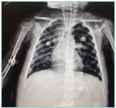
Anteroposterior (AP) chest radiograph of a pediatric patient undergoing high-frequency oscillatory ventilation (HFOV) for Acute Respiratory Distress Syndrome (ARDS). The image displays bilateral, diffuse interstitial and alveolar infiltrates with a ground-glass appearance, indicating residual inflammatory or infectious processes. There is a visible asymmetric opacity in the right hemithorax, though an overall improvement is noted compared to typical acute ARDS presentation. Key medical devices are present: a centrally positioned endotracheal tube (ET) for mechanical ventilation, a peripherally inserted central catheter (PICC) or peripheral line entering through the right arm, and circular ECG electrodes on the anterior chest wall. An enteric tube (nasogastric or orogastric) is seen extending toward the stomach. Lung volumes appear adequately maintained without significant atelectasis. The mediastinum is midline, and the osseous structures including the ribs and clavicles are intact and normally oriented for age. This diagnostic image serves as an educational example of monitoring pulmonary improvement and device placement in a critical care setting.
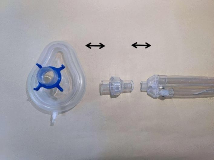
This clinical photograph serves as a schematic diagram illustrating the assembly of a non-invasive high-frequency oscillatory ventilation (NIHFOV) circuit. The image displays three primary medical device components arranged horizontally on a neutral background, with double-ended black arrows indicating the connection sequence. From left to right, the components include: 1) A clear, teardrop-shaped silicone non-invasive ventilation (NIV) mask featuring a blue four-pronged headgear attachment ring and a distal sampling port. 2) A clear, cylindrical disposable leak valve designed to facilitate the venting of exhaled CO2. 3) A proximal segment of a flexible, transparent ventilator breathing circuit showing multi-lumen tubing. The setup demonstrates the critical interface between the ventilator tubing, the mandatory leak valve for safety and gas exchange, and the patient interface (mask). This visual is intended for clinical training and educational instruction on the proper configuration of NIHFOV hardware for respiratory support.
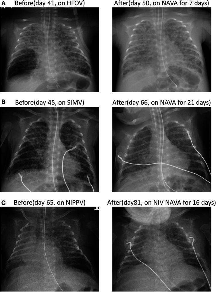
This comparison chart consists of six anteroposterior neonatal chest X-rays organized into three cases (A, B, and C) to demonstrate the resolution of localized pulmonary interstitial emphysema (PIE). Each case provides a 'Before' image—on High-Frequency Oscillatory Ventilation (HFOV), Synchronized Intermittent Mandatory Ventilation (SIMV), or Nasal Intermittent Positive Pressure Ventilation (NIPPV)—and an 'After' image following treatment with Neurally Adjusted Ventilatory Assist (NAVA) or Non-Invasive NAVA. In the 'Before' images, localized PIE is identified by abnormal collections of air within the interstitial space, appearing as cystic, radiolucent (dark) bubbles and coarse lung markings, primarily in the right lower lobe (Cases A and B) and left lower lobe (Case C). Medical devices including endotracheal tubes, umbilical venous catheters, and ECG leads are visible. The 'After' images show significant radiological improvement, characterized by the disappearance of the lucent cystic lesions, more homogenous lung parenchymal density, and improved lung aeration, illustrating the clinical efficacy of NAVA in managing neonatal air leak syndromes.
High-Frequency Oscillatory Ventilation (HFOV)
Definition and Basic Principle
- Adult frequencies: 120-900 breaths/min (2-15 Hz)
- Tidal volumes: typically < 100 mL in adults; below anatomic dead space
- Pediatric frequencies: 6-14 Hz; piston oscillates up to 840 times/min
How the Machine Works
| Parameter | Function |
|---|---|
| Mean Airway Pressure (mPAw/MAP) | Controls oxygenation; set ~5 cmH2O above last MAP on conventional ventilation |
| Amplitude (ΔP) | Distance the piston travels; controls CO2 removal |
| Frequency (Hz) | Rate of oscillations; inversely related to VT - lower Hz = larger VT = more CO2 clearance |
| FiO2 | Set as in conventional ventilation |
| I:E ratio | Usually 1:2 |
Initial Frequency Settings by Weight (Pediatric)
| Patient Weight (kg) | Initial Frequency (Hz) |
|---|---|
| < 2 | 15 |
| 2-15 | 10 |
| 16-20 | 8 |
| > 20 | 6-8 |
Unique Feature: Active Expiration
Theoretical Advantages
- Minimizes alveolar overdistension and derecruitment - the small tidal pressure swings avoid cyclical stretch injury (volutrauma and atelectrauma)
- High mean airway pressure prevents alveolar collapse without the cyclic opening/closing seen in conventional ventilation
- Ultimate lung-protective strategy - HFOV has been described as the logical extreme of the low-tidal-volume concept (Fishman's Pulmonary Diseases)
- In pediatrics: better chest wall compliance allows effective oscillation, and rescue use has shown benefit in PARDS
Clinical Evidence: Adults
- OSCAR trial (2013): Negative - no mortality benefit vs. conventional ventilation
- OSCILLATE trial (2013): Stopped early due to increased mortality in the HFOV group
- Conclusion: HFOV should NOT be used routinely in adults with ARDS; it is reserved only as a rescue ("salvage") mode for refractory hypoxemia unresponsive to conventional lung-protective strategies, and only by experienced clinicians
Clinical Evidence: Pediatrics
- Arnold et al. (1994): Only multicenter RCT in pediatric ARDS - showed lower oxygen supplementation at 30 days in HFOV group
- Several single-center studies show benefit as rescue therapy in PARDS
- In immunocompromised children with severe PARDS and post-hematopoietic cell transplant patients: early HFOV has decreased mortality
- Bateman et al. (RESTORE reanalysis): Early HFOV associated with longer mechanical ventilation, no mortality benefit
- Likely to remain useful for air leak syndrome and congenital diaphragmatic hernia in neonates/children
Current Indications (where HFOV may be considered)
- Rescue therapy for refractory hypoxemia in ARDS after failure of conventional lung-protective ventilation
- Pediatric ARDS (PARDS) - as rescue
- Air leak syndromes (pulmonary interstitial emphysema, pneumothorax with ongoing air leak)
- Congenital diaphragmatic hernia
- Listed alongside ECMO, inhaled NO, prone positioning as a "salvage" intervention (Fishman's Table 141-12)
Troubleshooting Hypercarbia During HFOV
- Suction - use inline suction (without breaking circuit) to clear ETT and ensure patency
- Increase ΔP (amplitude) - maximizes lung recruitment and minute ventilation
- Decrease frequency (Hz) - allows larger tidal volumes per oscillation
- Deflate ETT cuff - allows additional CO2 escape around tube
Disadvantages
- Requires full sedation and paralysis (no partial ventilatory support; spontaneous breathing not permitted)
- Hemodynamic compromise - higher MAP reduces venous return and cardiac output
- Airway clearance is impaired; secretion management is challenging
- Loss of recruitment if circuit is disconnected (for suctioning or manual ventilation)
- Requires specialized oscillator equipment and experienced operators