
sagittal plane analysis in gait
sagittal plane gait analysis joint angles hip knee ankle
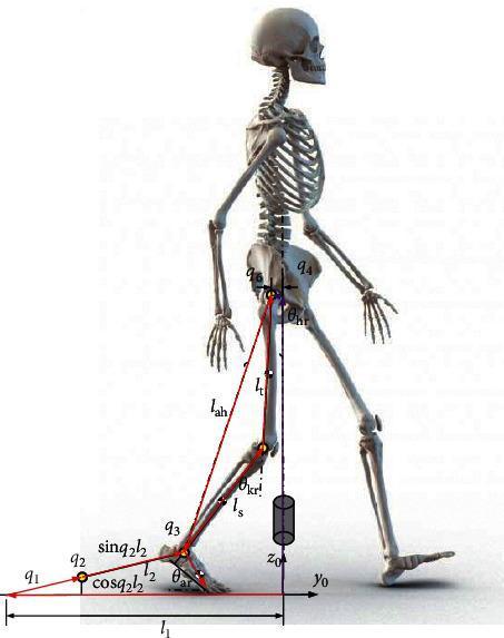
This anatomical and kinematic diagram depicts a human skeletal model in the sagittal plane, used for gait analysis and robotic rehabilitation modeling. The visual combines a full skeletal structure—showing the skull, spine, ribcage, pelvis, and lower limbs—with a mathematical overlay defining movement parameters. Key kinematic features include segment lengths labeled as 'lt' (thigh), 'ls' (shank), and 'lah' (hip-to-ankle distance), along with joint angles represented by 'q' variables (q1-q4, q6) and specific anatomical angles θar (ankle), θkr (knee), and θhr (hip). A local coordinate system (y0, z0) is established at the ground plane to calculate spatial positioning. Red vectors and trigonometric notations like 'sin(q2)l2' and 'cos(q2)l2' illustrate the vectorial method for determining joint locations and foot trajectories during a gait cycle. This model serves as an educational and engineering tool for developing robotic gait trainers (RGT), focusing on the biomechanics of the lower limb during walking or sit-to-stand transitions.
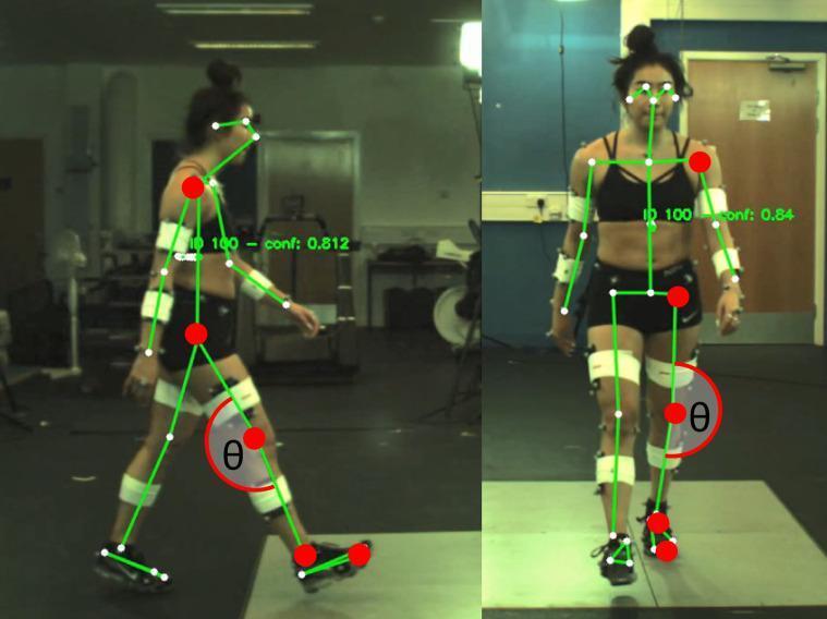
This clinical photograph displays a comparative view of 2D markerless motion capture during a gait analysis study. The image is split into two panels: the left shows a sagittal plane view of a participant walking, and the right shows a frontal plane view as the participant walks toward the camera. Superimposed on the images is a skeletal framework generated by the OpenPose algorithm. Key joint centers including the shoulder, hip, knee, ankle, and metatarsophalangeal (MTP) joints are identified by red and white circular markers. Green lines connect these markers to illustrate limb segments. In both views, a red arc labeled with the Greek letter 'theta' (θ) indicates the calculation of the knee joint angle, illustrating the geometric relationship between the hip, knee, and ankle. The participant is also equipped with retroreflective markers on wraps for simultaneous 3D marker-based motion capture validation. This visual serves to demonstrate the capability of markerless systems to estimate clinical gait parameters like joint angles and center locations in a laboratory setting.
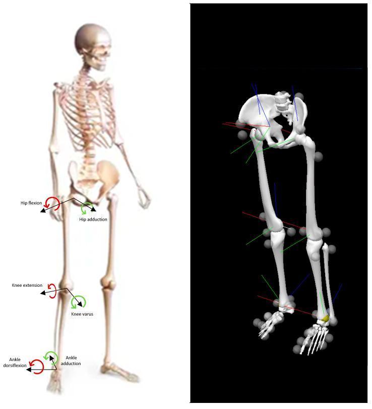
This medical anatomical diagram and biomechanical illustration demonstrate the nomenclature for lower limb movements and joint angles across the frontal and sagittal planes. The image is split into two panels: a left anatomical model and a right biomechanical skeletal model. The left panel shows a human skeleton with labeled arrows indicating joint kinetics. Red arrows denote sagittal plane movements, including hip flexion, knee extension, and ankle dorsiflexion. Green arrows denote frontal plane movements, including hip adduction, knee varus, and ankle adduction. The right panel displays a 3D biomechanical reconstruction of the pelvis and lower limbs. This model incorporates spherical motion-capture markers at key anatomical landmarks (hips, knees, ankles, and feet) and local coordinate systems represented by red, green, and blue axes. These elements illustrate the methodology for quantifying three-dimensional joint kinematics and kinetics during clinical gait analysis or functional movement tasks. The graphic serves as a foundational reference for understanding biomechanical modeling and the clinical description of lower limb orthopedic motion.
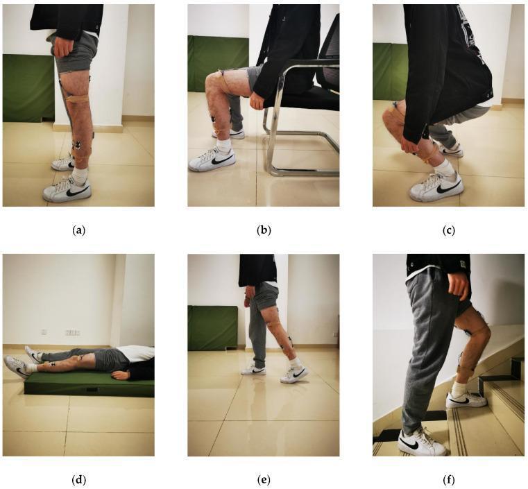
A series of clinical photographs illustrating Activities of Daily Living (ADLs) as part of a kinesiology or physical therapy gait and movement analysis. The composite image shows a human subject performing six distinct postural and ambulatory tasks: (a) standing with neutral joint alignment; (b) sitting with hip and knee flexion; (c) squatting showing maximum flexion of the hips, knees, and ankles; (d) lying supine; (e) walking capturing the gait cycle; and (f) ascending stairs demonstrating unilateral weight-bearing flexion. In each frame, the subject has medical-grade sensors (Inertial Measurement Units and sEMG) attached via adhesive tape and bandages to the lateral thigh and shank to monitor joint kinematics and muscle activity. The visual content serves to demonstrate the range of motion (ROM) and biomechanical transitions between static and dynamic states, essential for human activity recognition (HAR) studies, rehabilitation monitoring, and orthopedic assessment. The focus is on the sagittal plane biomechanics of the lower extremities including hip, knee, and ankle joint angles.
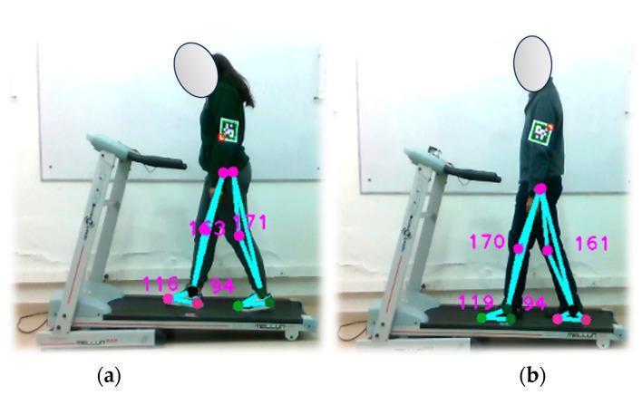
This composite image (labeled a and b) demonstrates an optical motion capture system used for gait analysis during a walking test on an electric treadmill. Two human subjects are shown in the sagittal plane, walking at a controlled speed of 1.5 km/h in an indoor laboratory environment. The visual illustrates markerless pose estimation and pedometer functionality. Overlaying the subjects' lower limbs are pink dots representing anatomical joint centers (hip, knee, ankle, and metatarsophalangeal joints) and light blue lines defining limb segments. Numerical values in magenta indicate joint angles or distances, facilitating the assessment of joint amplitude and gait cycle phases. ArUco markers are affixed to the upper arms for supplemental positional tracking. The setup is designed for the diagnostic assessment of gait-related conditions, utilizing a depth camera to monitor kinematic parameters like stride length, foot positioning, and limb synchronization. Factors such as attire contrast and lighting are critical for the accuracy of these biomechanical measurements.
"gait analysis" AND "sagittal plane" AND kinematics
Sagittal Plane Analysis in Gait
Why sagittal plane dominates
Segment-by-segment sagittal kinematics through the gait cycle
- Normally shows a small anterior/posterior tilt excursion (~2-4 degrees) with two oscillations per cycle.
- Excessive anterior tilt is common in hip flexor contracture or crouch gait; posterior tilt/retroversion patterns are seen in some neuromuscular gait disorders - Imaging Anatomy Text and Atlas Vol. 3, p. 1387-1389.
- At initial contact: ~20-30 degrees of flexion.
- Progressive extension through stance, reaching peak extension (~10 degrees) near terminal stance/pre-swing.
- Rapid flexion begins in late stance/early swing to advance the limb, peaking again near terminal swing before the cycle repeats.
- Total sagittal excursion is roughly 40-45 degrees.
- At initial contact, the knee is near full extension (about 5 degrees of flexion).
- As the limb is loaded, it flexes to roughly 15 degrees (loading response - shock absorption), then extends again toward mid-stance.
- Around 50% of the cycle, the contralateral foot contacts the ground and weight shifts, so the knee begins to flex again; the foot leaves the ground around 60%, and the knee flexes further into swing (peak flexion ~60 degrees) to allow toe clearance, then extends again before the next initial contact - Firestein & Kelley's Textbook of Rheumatology, p. 618-702.
- Slight plantarflexion at initial contact, moving into dorsiflexion through stance as the tibia advances over the fixed foot.
- A rapid plantarflexion "push-off" occurs at terminal stance/pre-swing (generating propulsion).
- Dorsiflexion follows in swing to clear the foot off the ground, returning to near-neutral by the next initial contact.
Clinical relevance
- Stiff-knee gait (reduced knee flexion in swing, often from spastic rectus femoris) - relevant in cerebral palsy management, where surgical correction (e.g., rectus femoris transfer) is guided by sagittal kinematic data - Campbell's Operative Orthopaedics, p. 2061-2081.
- Crouch gait (excessive hip/knee flexion, ankle dorsiflexion throughout stance).
- Excessive anterior pelvic tilt with hip flexion contracture.
- Loss of sagittal ankle motion is generally better tolerated functionally than equivalent losses at the hip or knee, since normal gait "requires" more sagittal excursion at the proximal joints for activities of daily living - Campbell's Operative Orthopaedics, p. 4949-4962.
Measurement methods
Frontal plane analysis for bachelor students written exam point of view
frontal plane gait pelvic obliquity Trendelenburg knee varus valgus
"frontal plane" AND gait AND kinematics
Frontal Plane Analysis in Gait — Exam-Focused Summary
1. What it is
2. Segment-by-segment findings (exam checklist)
| Segment | Frontal plane motion | Normal range | Key muscle control |
|---|---|---|---|
| Trunk | Slight lateral lean toward stance limb | Minimal (~a few degrees) | Erector spinae, lateral trunk muscles; excess lean = compensation strategy |
| Pelvis | Pelvic drop (contralateral side falls) and pelvic hike (rises) | ~6-10 degrees total excursion at normal walking speed | Hip abductors (gluteus medius/minimus, tensor fasciae latae) of the stance limb |
| Hip | Adduction in early-mid stance, slight abduction in swing | ~ 4-8 degrees adduction in stance | Abductors resist the adduction moment from body weight |
| Knee | Small varus/valgus excursion (normally minimal) | A few degrees; increased in pathology | Ligamentous/muscular stability; excess = malalignment risk |
| Ankle/foot | Eversion/inversion, subtalar motion | Small excursion | Peroneals (eversion) vs. tibialis posterior (inversion) |
| Base of support (step width) | Distance between the two feet | ~ 8 cm average | Reflects overall mediolateral balance strategy |
3. Core physiological concept — pelvic stabilization in single-limb stance
- Normal one-legged stance: small gluteal muscles on the stance side stabilize the pelvis in the coronal plane - General Anatomy and Musculoskeletal System (THIEME Atlas), p. 1338.
4. Classic pathological patterns (high-yield for exams)
- Cause: weakness or paralysis of gluteus medius/minimus (e.g., superior gluteal nerve injury, hip pathology, faulty IM injection).
- Finding: pelvis sags/drops toward the unsupported (swing) side during stance on the affected limb, because the weak abductors cannot stabilize the pelvis - General Anatomy and Musculoskeletal System (THIEME Atlas), p. 1341.
- Bilateral weakness produces a waddling gait.
- The patient leans the trunk toward the affected (stance) side.
- This shifts the center of gravity over the stance hip, reducing the demand on the weak abductors and keeping the pelvis level or even elevating it on the swing side - General Anatomy and Musculoskeletal System (THIEME Atlas), p. 1341.
- Key exam distinction: Trendelenburg = pelvis drops on swing side (uncompensated); Duchenne = trunk lurches toward stance side (compensated).
- Bilateral gluteal weakness (myopathy, bilateral hip disease) causing exaggerated pelvic drop/hike alternating side to side with an exaggerated lateral trunk sway - Adams and Victor's Principles of Neurology, p. 822-828.
- Genu valgum/varum (knee frontal plane malalignment) alters the frontal plane knee adduction moment during stance and is linked to compartmental loading in knee osteoarthritis — relevant to why frontal plane knee moments are measured in OA rehab research (Firestein & Kelley's Textbook of Rheumatology, references section).
- Leg length discrepancy: the pelvis cannot be held level on the shortened side without compensation (increased knee flexion on the long side, or circumduction), producing visible frontal/sagittal compensations - General Anatomy and Musculoskeletal System (THIEME Atlas), p. 379.
5. Simple exam answer template
- Definition - motion/forces in medial-lateral direction viewed from front/back.
- Segments assessed - trunk, pelvis (drop/hike), hip (add/abduction), knee (varus/valgus), ankle/foot (inversion/eversion), step width.
- Key physiological principle - hip abductor control of pelvic level during single-limb stance.
- Clinical correlation - Trendelenburg sign vs. Duchenne (compensated) gait, waddling gait, genu valgum/varum effects.
- Clinical relevance/why it matters - detects abductor weakness, joint malalignment, fall risk, guides orthopedic/neurologic diagnosis and rehab planning.
Supplementary recent evidence
Determinants of Gait
"determinants of gait" energy expenditure walking
Determinants of Gait — Exam-Focused Summary
1. Definition
2. The Six Determinants (high-yield list)
| # | Determinant | Mechanism | Effect |
|---|---|---|---|
| 1 | Pelvic rotation | Pelvis externally rotates from initial contact (IC) to pre-swing (PSw), then internally rotates during PSw and swing (~4 degrees each side, ~8 degrees total transverse plane excursion) | Effectively lengthens the limb at IC/toe-off, flattening the arc of the COM and reducing vertical displacement |
| 2 | Pelvic tilt (pelvic list) | The non-weight-bearing (swing side) hemipelvis drops about 5 degrees, controlled eccentrically by the stance-limb hip abductors | Reduces the amount the COM would otherwise rise, "shaving off" the top of the sinusoidal curve |
| 3 | Knee flexion in stance (early stance knee flexion) | Stance-phase knee flexes to about 15 degrees shortly after IC | Dampens the impact of loading and slightly shortens the limb, smoothing the COM trajectory |
| 4 | Foot and ankle mechanism | Controlled motion through the ankle and subtalar joint (heel-rocker, ankle-rocker, forefoot-rocker) | Dampens the loading response, provides stability in midstance, and efficient push-off/propulsion |
| 5 | Knee mechanism (knee-ankle-foot interaction) | The knee flexes at IC and extends by midstance, working together with the foot/ankle rockers | Minimizes unnecessary limb-length changes and unnecessary COM excursion during stance |
| 6 | Lateral pelvic displacement | The pelvis/trunk shifts about 5 cm laterally over the weight-bearing limb during single-limb support | Narrows the effective base of support, keeps the COM over the stance foot, and increases stance-phase stability |
3. Underlying principle to state in an exam answer
"The COM of the body normally follows a smooth, low-amplitude sinusoidal path (about 4-5 cm vertical and 4-5 cm lateral excursion) during walking. Each determinant of gait contributes to flattening this path, thereby reducing the mechanical work and metabolic energy required to walk."
4. Quick differentiation from the frontal/sagittal plane topics already discussed
- Determinants #1 (pelvic rotation) is a transverse plane motion.
- Determinants #2 (pelvic tilt/list) and #6 (lateral pelvic displacement) are frontal plane phenomena — directly tied to the hip abductor/Trendelenburg discussion from before.
- Determinants #3, #4, #5 (knee flexion, ankle/foot mechanism, knee-ankle coordination) are primarily sagittal plane motions — directly tied to the sagittal plane discussion from before.
5. Muscle action note (often asked as a follow-up)
Supplementary note on current literature
Title - Overcoming roadblocks of competency based education in Physiotherapy. this is my upcoming title for panel dicussion
competency based education physiotherapy roadblocks challenges implementation
"competency-based education" AND physiotherapy
barriers to competency based medical education implementation faculty resistance assessment
PMID: 28598747
PMID: 38660438
PMID: 40794487
Panel Discussion Brief: "Overcoming Roadblocks of Competency-Based Education in Physiotherapy"
1. Framing the Topic (opening context)
- APTA (US) released a 2025 report defining 19 entrustable professional activities, 8 domains of competence, and 54 competencies as a first step toward a CBE framework for entry-level practice.
- India and other countries have piloted structured competency-based internship models to standardize clinical readiness - Nair et al., 2024 (PMID: 38660438).
2. Core Roadblocks (organize the panel around these clusters)
- Lack of a unified, standardized competency framework - programs define competencies differently, creating inconsistency in graduate preparedness (APTA 2025 report; Burns et al., 2026, PMID: 40794487).
- Misalignment between regulatory bodies, accreditation standards, and training institutions - Caverzagie et al. identify this as one of four "overarching challenges" to CBME anywhere in health professions education (PMID: 28598747).
- Rigid academic calendars/credit-hour systems that don't accommodate variable-paced, mastery-based progression.
- Faculty workload and time constraints - the most frequently cited barrier across a 2026 scoping review of 19 CBE implementation studies (all 19 studies reported this).
- Inadequate faculty preparation/training in competency-based assessment methods (e.g., structured clinical assessments, entrustment scales).
- Resistance to change - faculty comfort with traditional grading/exam models; skepticism about subjective competency judgments.
- Documentation and assessment burden - faculty asked to conduct more frequent, structured formative assessments without added time or support.
- Feasibility of valid, reliable, and standardized competency assessment tools (cited as a barrier in 16/19 studies in the 2026 scoping review).
- Difficulty assessing "soft" competencies - professionalism, communication, clinical reasoning, affective/adaptive expertise (Burns et al. specifically note physical therapy educators uniquely emphasize affective development, which is harder to assess than technical skills).
- Need for programmatic/portfolio-based assessment infrastructure rather than one-off exams.
- Insufficient clinical placement capacity and inconsistent clinical supervisor training - stance-side clinical educators need calibration to judge competence uniformly.
- Inadequate institutional infrastructure and resources (identified in 15/19 studies as a barrier).
- Cost and logistics of individualized, self-paced progression (some students take longer to reach competency, disrupting cohort-based scheduling).
- Student anxiety around subjective, high-stakes competency judgments versus familiar numeric grading.
- Reduced motivation observed when assessments feel repetitive or poorly explained (echoed in faculty implementation studies from India's medical education CBME rollout).
- Disruption during crisis periods (e.g., COVID-19 significantly reduced formative assessment opportunities and skill-based competency evaluation in several reported implementations).
3. Strategies to Overcome Roadblocks (for the "solutions" half of the panel)
- Phased, context-sensitive implementation rather than a single "big bang" rollout - start with pilot cohorts (as Nair et al. did with a 27-intern pilot showing significant improvement in self-perceived competency, p<0.001) before scaling institution-wide.
- Faculty development programs (FDPs) focused specifically on competency-based assessment tools (e.g., mini-CEX style structured assessment forms, entrustment scales) - short, embedded 5-10 minute formative assessments reduce the "added burden" complaint.
- Build institutional/regulatory alignment early - engage accreditation bodies and regulatory councils before curriculum redesign so competency frameworks are recognized and supported, not fought against (Caverzagie's core recommendation).
- Standardize the competency language and outcomes across programs - adopt or adapt existing frameworks (APTA's domains/EPAs model, or WCPT/regional equivalents) rather than building from scratch.
- Invest in digital/portfolio tools for longitudinal tracking of competency attainment, reducing manual documentation burden on faculty.
- Calibrate clinical supervisors through structured training so competency judgments are consistent across different clinical sites and assessors.
- Communicate the "why" to students early - transparency about what mastery-based progression means and how it benefits their eventual clinical practice reduces anxiety and resistance.
- Leadership and stakeholder engagement - repeatedly identified across studies as the strongest facilitator counterbalancing every barrier above.
4. Suggested Panel Discussion Questions
- "What was the single biggest resistance point you faced when introducing CBE in your program, and how did you address it?"
- "How do you assess competencies that are hard to quantify, like clinical reasoning or professionalism, without it becoming subjective or inconsistent between assessors?"
- "Given limited clinical placement capacity, how realistic is individualized, mastery-paced progression at scale?"
- "What role should national regulatory/accreditation bodies play in standardizing physiotherapy competency frameworks?"
- "What would you tell a physiotherapy program starting its CBE journey today, based on what you wish you'd known?"
5. Key Sources for Panelists' Reference
- Caverzagie KJ et al., "Overarching challenges to the implementation of competency-based medical education," Medical Teacher, 2017 (PMID: 28598747) - the four-challenges framework, highly cited (261+ citations), applicable across health professions.
- Nair SP et al., "Transformation of Mandatory Physiotherapy Internship into A Structured Competency-Based Program: A Pilot Study," 2024 (PMID: 38660438) - physiotherapy-specific pilot data.
- Burns RL et al., "From Concept to Practice: Faculty Perceptions on Operationalizing Competency-Based Education in Physical Therapy," 2026 (PMID: 40794487) - qualitative faculty-perspective study, six themes/18 subthemes on CBE implementation in PT specifically.
- APTA, "Competency-Based Education in Physical Therapy: Essential Outcomes for Physical Therapist Entrance Into Practice," 2025 report.
- Shumba TW & Tekian A, "Competencies of undergraduate physiotherapy education: A scoping review," South African Journal of Physiotherapy, 2024 (PMID: 38322654).
- 2026 scoping review, "Implementation of outcome (competency) based medical education: a scoping review of 30 years of evidence" - cross-profession barrier/facilitator data (time constraints, faculty readiness, institutional leadership, assessment feasibility, infrastructure).
Active and passive insufficiency explain
active insufficiency passive insufficiency two joint muscle hamstring rectus femoris
Active and Passive Insufficiency
1. Active Insufficiency
2. Passive Insufficiency
3. Quick Comparison Table (exam-ready)
| Feature | Active Insufficiency | Passive Insufficiency |
|---|---|---|
| What fails | Muscle's ability to shorten enough | Muscle's ability to lengthen/stretch enough |
| Occurs when | Muscle tries to contract across 2 joints simultaneously in the same direction of shortening | Muscle is stretched across 2 joints simultaneously in the same direction of lengthening |
| Hamstring example | Hip extended + trying to flex knee fully → can't shorten enough | Knee extended + trying to flex hip fully (e.g., straight leg raise) → can't stretch enough |
| Clinical test example | Active knee flexion with hip in extension | Straight leg raise test, Thomas test, sit-and-reach |
| Underlying property tested | Contractile (active) muscle length-tension relationship | Passive tissue extensibility (muscle-tendon unit and connective tissue) |
4. Why this matters clinically/exam relevance
- Explains why straight-leg raise range is less than hip flexion range with the knee bent (passive insufficiency of hamstrings).
- Explains why you get more knee flexion range when the hip is flexed than when it's extended (avoiding active insufficiency of hamstrings).
- Relevant to muscle length testing (Thomas test, Ely's test, 90/90 hamstring test), stretching prescription, and understanding why biarticular muscles limit combined-joint range of motion in both directions.
- Ties back to the gait/kinesiology theme from your earlier questions - biarticular muscles like the rectus femoris and hamstrings play key roles in the sagittal-plane knee/hip mechanisms discussed in the "determinants of gait," and active/passive insufficiency explain some of the functional constraints on those muscles during swing and stance phases (e.g., stiff-knee gait from rectus femoris overactivity relates conceptually to a functional analog of active insufficiency limiting knee flexion in swing).


generate a pdf with daigrams also and in easiest way a student can attempt in exam
Sagittal Plane Analysis in Gait
Why sagittal plane dominates
Segment-by-segment sagittal kinematics through the gait cycle
- Normally shows a small anterior/posterior tilt excursion (~2-4 degrees) with two oscillations per cycle.
- Excessive anterior tilt is common in hip flexor contracture or crouch gait; posterior tilt/retroversion patterns are seen in some neuromuscular gait disorders - Imaging Anatomy Text and Atlas Vol. 3, p. 1387-1389.
- At initial contact: ~20-30 degrees of flexion.
- Progressive extension through stance, reaching peak extension (~10 degrees) near terminal stance/pre-swing.
- Rapid flexion begins in late stance/early swing to advance the limb, peaking again near terminal swing before the cycle repeats.
- Total sagittal excursion is roughly 40-45 degrees.
- At initial contact, the knee is near full extension (about 5 degrees of flexion).
- As the limb is loaded, it flexes to roughly 15 degrees (loading response - shock absorption), then extends again toward mid-stance.
- Around 50% of the cycle, the contralateral foot contacts the ground and weight shifts, so the knee begins to flex again; the foot leaves the ground around 60%, and the knee flexes further into swing (peak flexion ~60 degrees) to allow toe clearance, then extends again before the next initial contact - Firestein & Kelley's Textbook of Rheumatology, p. 618-702.
- Slight plantarflexion at initial contact, moving into dorsiflexion through stance as the tibia advances over the fixed foot.
- A rapid plantarflexion "push-off" occurs at terminal stance/pre-swing (generating propulsion).
- Dorsiflexion follows in swing to clear the foot off the ground, returning to near-neutral by the next initial contact.
Clinical relevance
- Stiff-knee gait (reduced knee flexion in swing, often from spastic rectus femoris) - relevant in cerebral palsy management, where surgical correction (e.g., rectus femoris transfer) is guided by sagittal kinematic data - Campbell's Operative Orthopaedics, p. 2061-2081.
- Crouch gait (excessive hip/knee flexion, ankle dorsiflexion throughout stance).
- Excessive anterior pelvic tilt with hip flexion contracture.
- Loss of sagittal ankle motion is generally better tolerated functionally than equivalent losses at the hip or knee, since normal gait "requires" more sagittal excursion at the proximal joints for activities of daily living - Campbell's Operative Orthopaedics, p. 4949-4962.
Measurement methods
1. What it is
2. Segment-by-segment findings (exam checklist)
| Segment | Frontal plane motion | Normal range | Key muscle control |
|---|---|---|---|
| Trunk | Slight lateral lean toward stance limb | Minimal (~a few degrees) | Erector spinae, lateral trunk muscles; excess lean = compensation strategy |
| Pelvis | Pelvic drop (contralateral side falls) and pelvic hike (rises) | ~6-10 degrees total excursion at normal walking speed | Hip abductors (gluteus medius/minimus, tensor fasciae latae) of the stance limb |
| Hip | Adduction in early-mid stance, slight abduction in swing | ~ 4-8 degrees adduction in stance | Abductors resist the adduction moment from body weight |
| Knee | Small varus/valgus excursion (normally minimal) | A few degrees; increased in pathology | Ligamentous/muscular stability; excess = malalignment risk |
| Ankle/foot | Eversion/inversion, subtalar motion | Small excursion | Peroneals (eversion) vs. tibialis posterior (inversion) |
| Base of support (step width) | Distance between the two feet | ~ 8 cm average | Reflects overall mediolateral balance strategy |
3. Core physiological concept — pelvic stabilization in single-limb stance
- Normal one-legged stance: small gluteal muscles on the stance side stabilize the pelvis in the coronal plane - General Anatomy and Musculoskeletal System (THIEME Atlas), p. 1338.
4. Classic pathological patterns (high-yield for exams)
- Cause: weakness or paralysis of gluteus medius/minimus (e.g., superior gluteal nerve injury, hip pathology, faulty IM injection).
- Finding: pelvis sags/drops toward the unsupported (swing) side during stance on the affected limb, because the weak abductors cannot stabilize the pelvis - General Anatomy and Musculoskeletal System (THIEME Atlas), p. 1341.
- Bilateral weakness produces a waddling gait.
- The patient leans the trunk toward the affected (stance) side.
- This shifts the center of gravity over the stance hip, reducing the demand on the weak abductors and keeping the pelvis level or even elevating it on the swing side - General Anatomy and Musculoskeletal System (THIEME Atlas), p. 1341.
- Key exam distinction: Trendelenburg = pelvis drops on swing side (uncompensated); Duchenne = trunk lurches toward stance side (compensated).
- Bilateral gluteal weakness (myopathy, bilateral hip disease) causing exaggerated pelvic drop/hike alternating side to side with an exaggerated lateral trunk sway - Adams and Victor's Principles of Neurology, p. 822-828.
- Genu valgum/varum (knee frontal plane malalignment) alters the frontal plane knee adduction moment during stance and is linked to compartmental loading in knee osteoarthritis — relevant to why frontal plane knee moments are measured in OA rehab research (Firestein & Kelley's Textbook of Rheumatology, references section).
- Leg length discrepancy: the pelvis cannot be held level on the shortened side without compensation (increased knee flexion on the long side, or circumduction), producing visible frontal/sagittal compensations - General Anatomy and Musculoskeletal System (THIEME Atlas), p. 379.
5. Simple exam answer template
- Definition - motion/forces in medial-lateral direction viewed from front/back.
- Segments assessed - trunk, pelvis (drop/hike), hip (add/abduction), knee (varus/valgus), ankle/foot (inversion/eversion), step width.
- Key physiological principle - hip abductor control of pelvic level during single-limb stance.
- Clinical correlation - Trendelenburg sign vs. Duchenne (compensated) gait, waddling gait, genu valgum/varum effects.
- Clinical relevance/why it matters - detects abductor weakness, joint malalignment, fall risk, guides orthopedic/neurologic diagnosis and rehab planning.
Supplementary recent evidence
1. Definition
2. The Six Determinants (high-yield list)
| # | Determinant | Mechanism | Effect |
|---|---|---|---|
| 1 | Pelvic rotation | Pelvis externally rotates from initial contact (IC) to pre-swing (PSw), then internally rotates during PSw and swing (~4 degrees each side, ~8 degrees total transverse plane excursion) | Effectively lengthens the limb at IC/toe-off, flattening the arc of the COM and reducing vertical displacement |
| 2 | Pelvic tilt (pelvic list) | The non-weight-bearing (swing side) hemipelvis drops about 5 degrees, controlled eccentrically by the stance-limb hip abductors | Reduces the amount the COM would otherwise rise, "shaving off" the top of the sinusoidal curve |
| 3 | Knee flexion in stance (early stance knee flexion) | Stance-phase knee flexes to about 15 degrees shortly after IC | Dampens the impact of loading and slightly shortens the limb, smoothing the COM trajectory |
| 4 | Foot and ankle mechanism | Controlled motion through the ankle and subtalar joint (heel-rocker, ankle-rocker, forefoot-rocker) | Dampens the loading response, provides stability in midstance, and efficient push-off/propulsion |
| 5 | Knee mechanism (knee-ankle-foot interaction) | The knee flexes at IC and extends by midstance, working together with the foot/ankle rockers | Minimizes unnecessary limb-length changes and unnecessary COM excursion during stance |
| 6 | Lateral pelvic displacement | The pelvis/trunk shifts about 5 cm laterally over the weight-bearing limb during single-limb support | Narrows the effective base of support, keeps the COM over the stance foot, and increases stance-phase stability |
3. Underlying principle to state in an exam answer
"The COM of the body normally follows a smooth, low-amplitude sinusoidal path (about 4-5 cm vertical and 4-5 cm lateral excursion) during walking. Each determinant of gait contributes to flattening this path, thereby reducing the mechanical work and metabolic energy required to walk."
4. Quick differentiation from the frontal/sagittal plane topics already discussed
- Determinants #1 (pelvic rotation) is a transverse plane motion.
- Determinants #2 (pelvic tilt/list) and #6 (lateral pelvic displacement) are frontal plane phenomena — directly tied to the hip abductor/Trendelenburg discussion from before.
- Determinants #3, #4, #5 (knee flexion, ankle/foot mechanism, knee-ankle coordination) are primarily sagittal plane motions — directly tied to the sagittal plane discussion from before.
5. Muscle action note (often asked as a follow-up)
Supplementary note on current literature
1. Framing the Topic (opening context)
- APTA (US) released a 2025 report defining 19 entrustable professional activities, 8 domains of competence, and 54 competencies as a first step toward a CBE framework for entry-level practice.
- India and other countries have piloted structured competency-based internship models to standardize clinical readiness - Nair et al., 2024 (PMID: 38660438).
2. Core Roadblocks (organize the panel around these clusters)
- Lack of a unified, standardized competency framework - programs define competencies differently, creating inconsistency in graduate preparedness (APTA 2025 report; Burns et al., 2026, PMID: 40794487).
- Misalignment between regulatory bodies, accreditation standards, and training institutions - Caverzagie et al. identify this as one of four "overarching challenges" to CBME anywhere in health professions education (PMID: 28598747).
- Rigid academic calendars/credit-hour systems that don't accommodate variable-paced, mastery-based progression.
- Faculty workload and time constraints - the most frequently cited barrier across a 2026 scoping review of 19 CBE implementation studies (all 19 studies reported this).
- Inadequate faculty preparation/training in competency-based assessment methods (e.g., structured clinical assessments, entrustment scales).
- Resistance to change - faculty comfort with traditional grading/exam models; skepticism about subjective competency judgments.
- Documentation and assessment burden - faculty asked to conduct more frequent, structured formative assessments without added time or support.
- Feasibility of valid, reliable, and standardized competency assessment tools (cited as a barrier in 16/19 studies in the 2026 scoping review).
- Difficulty assessing "soft" competencies - professionalism, communication, clinical reasoning, affective/adaptive expertise (Burns et al. specifically note physical therapy educators uniquely emphasize affective development, which is harder to assess than technical skills).
- Need for programmatic/portfolio-based assessment infrastructure rather than one-off exams.
- Insufficient clinical placement capacity and inconsistent clinical supervisor training - stance-side clinical educators need calibration to judge competence uniformly.
- Inadequate institutional infrastructure and resources (identified in 15/19 studies as a barrier).
- Cost and logistics of individualized, self-paced progression (some students take longer to reach competency, disrupting cohort-based scheduling).
- Student anxiety around subjective, high-stakes competency judgments versus familiar numeric grading.
- Reduced motivation observed when assessments feel repetitive or poorly explained (echoed in faculty implementation studies from India's medical education CBME rollout).
- Disruption during crisis periods (e.g., COVID-19 significantly reduced formative assessment opportunities and skill-based competency evaluation in several reported implementations).
3. Strategies to Overcome Roadblocks (for the "solutions" half of the panel)
- Phased, context-sensitive implementation rather than a single "big bang" rollout - start with pilot cohorts (as Nair et al. did with a 27-intern pilot showing significant improvement in self-perceived competency, p<0.001) before scaling institution-wide.
- Faculty development programs (FDPs) focused specifically on competency-based assessment tools (e.g., mini-CEX style structured assessment forms, entrustment scales) - short, embedded 5-10 minute formative assessments reduce the "added burden" complaint.
- Build institutional/regulatory alignment early - engage accreditation bodies and regulatory councils before curriculum redesign so competency frameworks are recognized and supported, not fought against (Caverzagie's core recommendation).
- Standardize the competency language and outcomes across programs - adopt or adapt existing frameworks (APTA's domains/EPAs model, or WCPT/regional equivalents) rather than building from scratch.
- Invest in digital/portfolio tools for longitudinal tracking of competency attainment, reducing manual documentation burden on faculty.
- Calibrate clinical supervisors through structured training so competency judgments are consistent across different clinical sites and assessors.
- Communicate the "why" to students early - transparency about what mastery-based progression means and how it benefits their eventual clinical practice reduces anxiety and resistance.
- Leadership and stakeholder engagement - repeatedly identified across studies as the strongest facilitator counterbalancing every barrier above.
4. Suggested Panel Discussion Questions
- "What was the single biggest resistance point you faced when introducing CBE in your program, and how did you address it?"
- "How do you assess competencies that are hard to quantify, like clinical reasoning or professionalism, without it becoming subjective or inconsistent between assessors?"
- "Given limited clinical placement capacity, how realistic is individualized, mastery-paced progression at scale?"
- "What role should national regulatory/accreditation bodies play in standardizing physiotherapy competency frameworks?"
- "What would you tell a physiotherapy program starting its CBE journey today, based on what you wish you'd known?"
5. Key Sources for Panelists' Reference
- Caverzagie KJ et al., "Overarching challenges to the implementation of competency-based medical education," Medical Teacher, 2017 (PMID: 28598747) - the four-challenges framework, highly cited (261+ citations), applicable across health professions.
- Nair SP et al., "Transformation of Mandatory Physiotherapy Internship into A Structured Competency-Based Program: A Pilot Study," 2024 (PMID: 38660438) - physiotherapy-specific pilot data.
- Burns RL et al., "From Concept to Practice: Faculty Perceptions on Operationalizing Competency-Based Education in Physical Therapy," 2026 (PMID: 40794487) - qualitative faculty-perspective study, six themes/18 subthemes on CBE implementation in PT specifically.
- APTA, "Competency-Based Education in Physical Therapy: Essential Outcomes for Physical Therapist Entrance Into Practice," 2025 report.
- Shumba TW & Tekian A, "Competencies of undergraduate physiotherapy education: A scoping review," South African Journal of Physiotherapy, 2024 (PMID: 38322654).
- 2026 scoping review, "Implementation of outcome (competency) based medical education: a scoping review of 30 years of evidence" - cross-profession barrier/facilitator data (time constraints, faculty readiness, institutional leadership, assessment feasibility, infrastructure).
1. Active Insufficiency
2. Passive Insufficiency
3. Quick Comparison Table (exam-ready)
| Feature | Active Insufficiency | Passive Insufficiency |
|---|---|---|
| What fails | Muscle's ability to shorten enough | Muscle's ability to lengthen/stretch enough |
| Occurs when | Muscle tries to contract across 2 joints simultaneously in the same direction of shortening | Muscle is stretched across 2 joints simultaneously in the same direction of lengthening |
| Hamstring example | Hip extended + trying to flex knee fully → can't shorten enough | Knee extended + trying to flex hip fully (e.g., straight leg raise) → can't stretch enough |
| Clinical test example | Active knee flexion with hip in extension | Straight leg raise test, Thomas test, sit-and-reach |
| Underlying property tested | Contractile (active) muscle length-tension relationship | Passive tissue extensibility (muscle-tendon unit and connective tissue) |
4. Why this matters clinically/exam relevance
- Explains why straight-leg raise range is less than hip flexion range with the knee bent (passive insufficiency of hamstrings).
- Explains why you get more knee flexion range when the hip is flexed than when it's extended (avoiding active insufficiency of hamstrings).
- Relevant to muscle length testing (Thomas test, Ely's test, 90/90 hamstring test), stretching prescription, and understanding why biarticular muscles limit combined-joint range of motion in both directions.
- Ties back to the gait/kinesiology theme from your earlier questions - biarticular muscles like the rectus femoris and hamstrings play key roles in the sagittal-plane knee/hip mechanisms discussed in the "determinants of gait," and active/passive insufficiency explain some of the functional constraints on those muscles during swing and stance phases (e.g., stiff-knee gait from rectus femoris overactivity relates conceptually to a functional analog of active insufficiency limiting knee flexion in swing).
i want only active apsive insufficiency with diagram
Expecting value: line 1 column 527 (char 526)
We encountered an error while processing your request. Please try again or reach out to us for help.
??
Importance and effect of exercises to maintain optimal health?? exercise for normal person a 15 mark question
Expecting value: line 1 column 527 (char 526)
We encountered an error while processing your request. Please try again or reach out to us for help.
Importance and effect of exercises to maintain optimal health?? exercise for normal person a 15 mark question
Expecting value: line 1 column 527 (char 526)
We encountered an error while processing your request. Please try again or reach out to us for help.
postural drainage notes with diagram
Expecting value: line 1 column 527 (char 526)
We encountered an error while processing your request. Please try again or reach out to us for help.