
Retinoscopy Question for pg student ophthalmology Reference kanski dukes ak khurana
retinoscopy with movement against movement reflex diagram
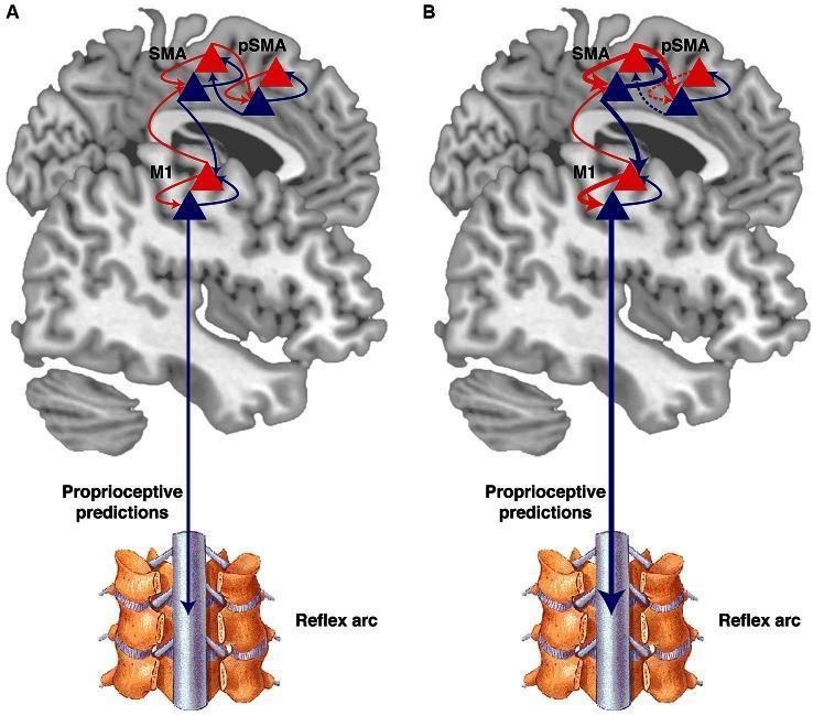
A pathophysiology diagram illustrating the active inference theory of voluntary movement and its disruption in psychogenic movement disorders (PMD). The graphic consists of two panels (A and B) featuring a sagittal view of the human brain and a segment of the spinal cord. In both panels, three cortical areas are highlighted: the pre-supplementary motor area (pSMA), supplementary motor area (SMA), and primary motor cortex (M1). Blue triangles represent 'prediction units' (beliefs), and red triangles represent 'prediction error units.' Blue arrows indicate backward projections (predictions), while red arrows indicate forward projections (error signaling). Diagram A depicts a normal hierarchy where predictions flow downward from the pSMA to the spinal cord via SMA and M1, inducing movement through reflex arcs. Diagram B illustrates the pathophysiology of PMD, showing abnormally high precision at intermediate levels. This is visualized by thickened arrows between SMA and M1, and a thickened descending arrow to the spinal cord. Conversely, the high-level connection from pSMA to SMA is represented by a dashed line, symbolizing a loss of agency where intermediate-level prediction errors overwhelm high-level intentional goals.
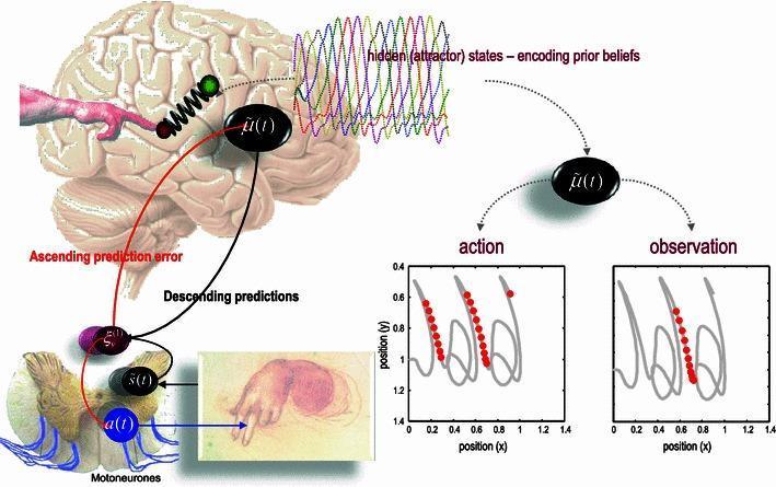
This medical schematic illustrates a neurobiological generative model for active inference, specifically focusing on action execution and observation. The top-left features a human brain overlay with a Lotka-Volterra attractor model, representing 'hidden states' or prior beliefs about movement trajectories. A spring-mass mechanism signifies the mapping of these dynamics to an extrinsic frame of reference. The model depicts a closed-loop system where 'Descending predictions' (black arrows) move from the cortical level to the spinal cord, and 'Ascending prediction errors' (red arrows) return to the brain. A cross-section of the spinal cord illustrates motoneurons and reflex arcs that execute movement. On the right, two plots compare 'action' and 'observation.' Both graphs map movement trajectories in a 2D space (position y vs. position x). Red dots superimposed on the gray trajectory lines indicate neuronal population firing (mirror neuron-like activity) when the agent performs the action and when observing the same action without proprioceptive input. This diagram is utilized in neuroscientific education to explain predictive coding, mirror neuron systems, and motor control theories.
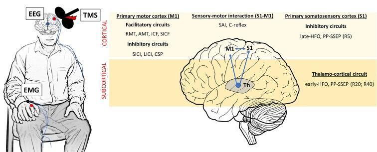
Educational infographic and anatomical diagram illustrating neurophysiological protocols for evaluating human cortical and subcortical circuits. The left panel shows a clinical setup of a seated subject with electroencephalogram (EEG) leads on the scalp, a transcranial magnetic stimulation (TMS) figure-eight coil over the motor cortex, and electromyography (EMG) electrodes on the forearm to record motor evoked potentials. The right panel displays a lateral brain schematic categorized into 'Cortical' and 'Subcortical' levels. Key regions include the Primary Motor Cortex (M1), Primary Somatosensory Cortex (S1), and Thalamus (Th). The diagram maps specific neurophysiological measures to these areas: M1 facilitatory (RMT, AMT, ICF, SICF) and inhibitory (SICI, LICI, CSP) circuits; S1 inhibitory circuits (late-HFO, PP-SSEP R5); and sensory-motor interactions (SAI, C-reflex). The subcortical section highlights the thalamo-cortical circuit evaluated via early-HFO and PP-SSEP (R20, R40). This visual serves as a summary of diagnostic electrophysiology for movement disorders and epilepsy research.
A pathophysiology diagram illustrating the sensorimotor pathway and biological architecture of movement. The flowchart consists of three main components connected by directional blue arrows, representing the sequence from sensory input to motor output. On the left, a clinical photograph of a human eye with a blue iris represents visual sensory input. An arrow points to a central anatomical illustration of a human brain, showing the cerebral cortex with detailed gyri and sulci, signifying central processing and motor planning. A second arrow leads to an anatomical diagram of a flexed human upper limb. This final component depicts the skeletal structure (scapula, humerus, radius, and ulna) with the biceps brachii muscle highlighted in red. The muscle is shown in a state of concentric contraction, indicated by its prominent bulge and the flexion of the elbow joint. The diagram serves as an educational summary of the integrated nervous and musculoskeletal systems, specifically illustrating how visual stimuli are processed by the brain to trigger muscular activation and biomechanical movement.
retinoscopy eye examination technique optics
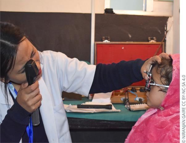
A clinical photograph illustrating a pediatric ophthalmic examination, specifically demonstrating the technique for 'wet' cycloplegic retinoscopy. A female medical professional in a white coat is shown in the left of the frame, holding a handheld retinoscope to her right eye. She is aiming the light through a trial frame fitted onto a young child positioned on the right. The practitioner uses her left hand to stabilize the trial frame on the child's face, ensuring proper alignment for refraction. The child is wearing a pink hooded garment. This procedure is typically performed after the administration of cycloplegic agents, such as cyclopentolate or tropicamide, to paralyze the ciliary muscle and prevent active accommodation, thereby allowing for an accurate objective measurement of the patient's refractive error. The background shows clinical supplies, including a lens trial set, indicating a professional optometric or ophthalmic setting.
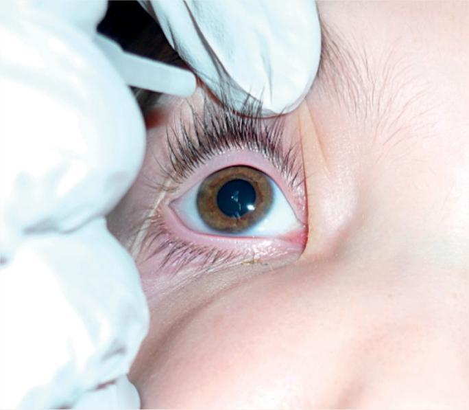
This clinical photograph demonstrates a medical procedural technique for ophthalmic drug administration. The image shows the eye of a patient with a brown iris and clear sclera. A healthcare provider wearing white examination gloves is seen gently retracting both the upper and lower eyelids. The lower eyelid is pulled downward (eversion) to expose the inferior conjunctival sac (fornix), creating a pocket for the instillation of eye drops or ointment. This specific technique is utilized in pediatric or non-cooperative patients to ensure ocular access without applying direct pressure to the globe. Key anatomical structures visible include the palpebral conjunctiva, eyelid margins with eyelashes, and the corneal surface. The image serves as an educational guide for nursing and clinical skills, focusing on proper patient handling and infection control through the use of gloves during topical ocular therapy.
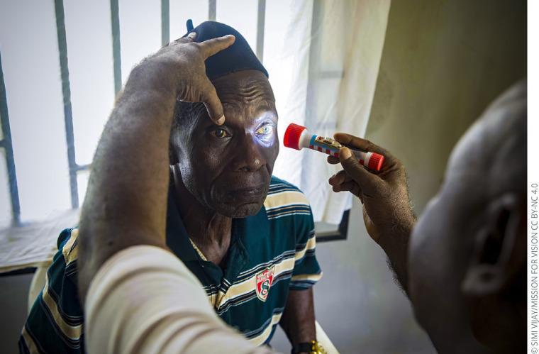
This clinical photograph captures a handheld torch examination (penlight test) performed on an elderly male patient in a primary care setting. An examiner is shown using a small flashlight to provide focal illumination to the patient's left eye. The technique illustrates the screening for leukocoria or dense lenticular opacities, as evidenced by the bright white/yellowish reflex visible within the pupillary area, which is highly suggestive of a mature cataract. A second individual is assisting by stabilizing the patient's forehead and elevating the upper eyelid to ensure clear visualization of the ocular surface and pupillary response. This image serves as an educational example of basic ophthalmic triage and physical examination techniques used by primary health workers to identify common causes of preventable blindness, such as cataracts, in resource-limited environments. The focus is on the diagnostic approach of using focal light to detect gross anatomical abnormalities of the anterior segment.
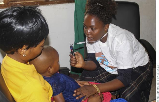
This clinical photograph illustrates a pediatric ophthalmic examination using the Arclight, a low-cost, portable, solar-powered direct ophthalmoscope and otoscope. The image shows a healthcare professional in a clinical setting in Tanzania performing an eye screening on a young child who is being held by a caregiver. The examiner is holding the slender, black, handheld device in her right hand, positioned at a close working distance to the child's eye to assess the red reflex or perform a fundoscopic examination. The device features a white neck lanyard for easy accessibility during field screenings. This visual demonstrates the practical application of frugal innovation in global health settings for the early detection of ocular conditions such as cataracts, retinoblastoma, and refractive errors in pediatric populations. The clinical focus is on the technique of direct ophthalmoscopy and the use of specialized diagnostic tools adapted for resource-limited environments.
RETINOSCOPY
PG Ophthalmology - Comprehensive Review
1. DEFINITION & PRINCIPLE
2. TYPES OF RETINOSCOPES
| Type | Mirror | Reflex Characteristic |
|---|---|---|
| Plane mirror retinoscope (older) | Flat/plane | Divergent light; reflex moves WITH the mirror movement in most cases |
| Concave mirror retinoscope | Concave | Convergent light |
| Streak retinoscope (Copeland) | Plane + linear streak | Most commonly used today |
| Spot retinoscope | Circular spot of light |
3. TYPES OF RETINOSCOPY
A. Static Retinoscopy
- Patient fixes a distant target to relax accommodation
- Used to determine the full refractive error
- Cycloplegic retinoscopy (wet retinoscopy): done after cycloplegic drops - mandatory in children to eliminate accommodation
B. Dynamic Retinoscopy (MEM - Monocular Estimation Method)
- Patient fixes a near target (attached to the retinoscope)
- Measures accommodative lag or lead
- Used in assessing binocular vision, accommodative dysfunction
- According to Kanski: adequacy of cycloplegia can be verified by comparing distance and near retinoscopy readings - if accommodation is fully paralyzed, the near and distance readings should be equal
C. Radical Retinoscopy
- Used in high myopes
- Examiner moves closer to reduce working distance
4. REFLEX MOVEMENTS - THE CORE CONCEPT
| Refractive State | Far Point Location | Reflex Movement |
|---|---|---|
| Emmetropia | Infinity | No movement (appears to fill entire pupil) |
| Myopia < 1/working distance | Behind examiner | Against movement |
| Myopia > 1/working distance | Between patient and examiner | With movement |
| Hypermetropia | Virtual point behind patient | With movement |
| Myopia = 1/working distance (i.e., far point exactly at examiner's eye) | At examiner's peephole | Neutralization |
- WITH movement = add PLUS lenses (hypermetropia or low myopia)
- AGAINST movement = add MINUS lenses (myopia beyond 1D)
Characteristics of the Reflex at Neutralization
- Reflex fills the entire pupil
- Bright, wide, fast-moving
- Any additional lens power causes a reversal to "against" movement
The Reflex in Astigmatism
- Break phenomenon: the reflex is not continuous across the cornea in astigmatism
- Skew phenomenon: streak and reflex are not parallel
- Examiner neutralizes each principal meridian separately
- The axis of astigmatism is where the streak and reflex are aligned (no skew)
5. WORKING DISTANCE & ALLOWANCE
- Standard working distance: 67 cm (0.67 m) or 1 meter
- Working distance allowance must be subtracted from the gross retinoscopy finding to get the net retinoscopy (actual refraction):
- At 1 meter: subtract +1.00 D (= 1/1 m)
- At 67 cm: subtract +1.50 D (= 1/0.67 m)
- At 50 cm: subtract +2.00 D (= 1/0.5 m)
6. CYCLOPLEGIC RETINOSCOPY (WET RETINOSCOPY)
- Children (under 16 years) - mandatory due to high accommodation
- Suspected accommodative esotropia
- Latent hypermetropia
- Any patient where manifest refraction differs significantly from expected
| Drug | Concentration | Onset | Duration | Notes |
|---|---|---|---|---|
| Cyclopentolate | 0.5% (<6 mo), 1% (>6 mo) | 30 min | 24 hrs (mydriasis) | Drug of choice for children |
| Atropine | 0.5% (<12 mo), 1% (>12 mo) | 1-3 days (instilled at home) | Up to 2 weeks | Used in heavy pigmentation, high hypermetropia, esotropia |
| Tropicamide | 1% | 20 min | 4-6 hrs | Adults, less complete cycloplegia |
| Homatropine | 2% | 45 min | 1-3 days | Intermediate |
7. SPECIAL RETINOSCOPIC REFLEXES
| Reflex | Associated Condition |
|---|---|
| Scissors reflex | Keratoconus, irregular astigmatism, lenticonus |
| Oil droplet reflex | Keratoconus (seen on retinoscopy and distant direct ophthalmoscopy at 0.5 m) |
| Dimming/absence of reflex | Media opacity - cataract, vitreous hemorrhage |
| Duochrome (bichrome) test | Endpoint refinement during subjective refraction |
| Dull/dark reflex | Posterior vitreous or retinal pathology |
8. FOGGING TECHNIQUE IN RETINOSCOPY
- +2.00 D or +3.00 D fogging lens placed before the patient's eye
- Blurs the fixation target, relaxing accommodation
- Retinoscopy is performed through this fog, then fog is removed from the final prescription
9. RETINOSCOPY IN SPECIFIC CONDITIONS
Keratoconus
- Scissors reflex is characteristic
- "Oil droplet" or Charleux sign on direct ophthalmoscopy at 0.5 m distance
- Retinoscopy is part of diagnosis along with corneal topography (Kanski)
Aphakia
- High plus correction needed; reflex is bright and wide with movement
Pseudophakia (IOL in situ)
- Retinoscopy useful to check residual refractive error
High Myopia (>6D)
- Against movement seen; radical retinoscopy (shorter working distance) used
Anisometropia
- Different lenses needed for each eye; potential for aniseikonia
10. ERRORS IN RETINOSCOPY
- Accommodative error: Not neutralized - underestimates hypermetropia, overestimates myopia (corrected by cycloplegia or fogging)
- Working distance error: Incorrect distance used; must be standardized and deducted
- Irregular astigmatism: Scissors reflex makes neutralization difficult
- Eccentric fixation: Patient not looking straight ahead
- Small pupil: Difficult to observe reflex clearly; tropicamide may be used for dilation
- Media opacities: Reduce the quality of reflex
- Examiner's refractive error: Examiner must wear their own correction during retinoscopy
11. COMPARISON: RETINOSCOPY vs AUTOREFRACTOMETRY
| Feature | Retinoscopy | Autorefractometer |
|---|---|---|
| Nature | Objective | Objective |
| Cycloplegia needed | Yes (in children) | Yes (in children) |
| Irregular astigmatism | Better (scissors reflex recognized) | Poor - gives average |
| Learning curve | High | Low |
| Gold standard | Yes (especially cycloplegic) | No - needs confirmation |
| Small pupils | Difficult | Very difficult |
12. HIGH-YIELD EXAM POINTS (PG Level)
- Plane mirror retinoscope at 1 m: with movement = hypermetropia or myopia <1D; against movement = myopia >1D
- Working distance deduction = 1/distance in meters (always deduct plus lens equal to working distance power)
- Scissors reflex = keratoconus / irregular cornea
- Oil droplet reflex = keratoconus (retinoscopy finding same as distant direct ophthalmoscopy)
- Cyclopentolate is the drug of choice for cycloplegic retinoscopy in children
- Atropine reserved for high hypermetropia, dark irides, esotropia, or when cyclopentolate fails
- Neutralization: reflex fills entire pupil, appears bright, any reversal means you've gone past neutral
- Dynamic retinoscopy: assesses lag of accommodation at near - useful in binocular vision assessment
- Fogging with +2D or +3D relaxes accommodation in adults during non-cycloplegic retinoscopy
- At birth most babies are hypermetropic - retinoscopy essential in pediatric squint workup
- Kanski's Clinical Ophthalmology: A Systematic Approach, 10th ed. - Chapter 18 (Strabismus, Cycloplegia, Refraction)
- Comprehensive Ophthalmology - AK Khurana
- Duke-Elder System of Ophthalmology - Vol. V (Ophthalmic Optics and Refraction)