
5 mark answer for condyalr fracture with schematic diagrams
Which condylar fracture are you asking about?
mandibular condyle fracture classification diagram
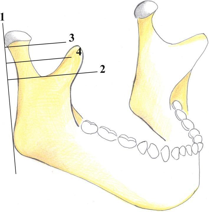
This medical anatomical diagram illustrates the AO Foundation's classification system for mandibular condyle fractures. The illustration depicts a lateral view of a human mandible, focusing on the condylar process, coronoid process, sigmoid notch, and mandibular angle. Four reference lines are utilized to categorize fracture locations: Line 1 is a vertical tangent to the posterior border of the condylar head and mandibular angle; Line 2 is horizontal and perpendicular to Line 1, passing through the deepest point of the sigmoid notch; Line 3 is parallel to Line 2, passing through the inferior margin of the condylar head; and Line 4 is situated equidistant between Lines 2 and 3. In this classification, fractures occurring above Line 3 are 'condylar head' fractures. Fractures between Line 3 and Line 4 are classified as 'high-neck' fractures, while those between Line 4 and Line 2 are 'low-neck' fractures. This standardized mapping aids oral and maxillofacial surgeons in diagnostic reporting and surgical planning for condylar injuries.
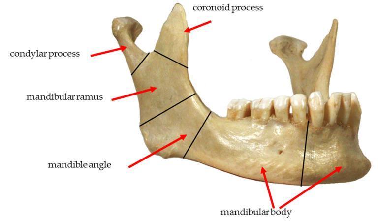
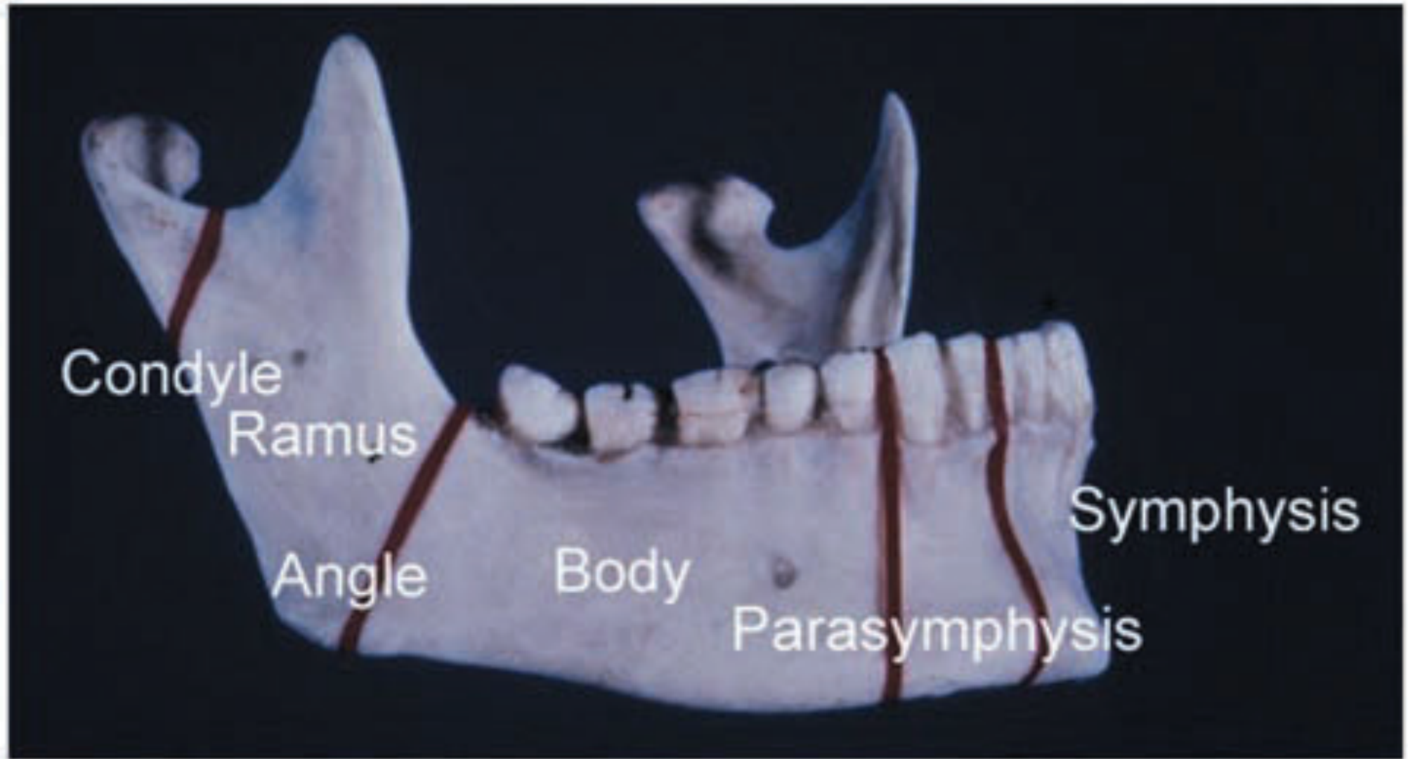
This clinical photograph displays a lateral view of a human mandible, used to illustrate the common anatomical zones for fracture classification. Black demarcating lines and red arrows label five primary regions: 1) The condylar process at the posterosuperior apex, representing the articular portion of the temporomandibular joint. 2) The coronoid process, a sharp, triangular projection anterior to the condyle. 3) The mandibular ramus, the vertical quadrilateral plate connecting the processes to the lower jaw. 4) The mandibular angle, located at the junction of the posterior and inferior borders. 5) The mandibular body, the horizontal portion extending anteriorly and housing the dentition. The image shows the alveolar ridge with integrated teeth and the mental foramen on the lateral surface of the body. This diagram serves as an educational tool for maxillofacial surgery and traumatology, specifically for identifying fracture locations such as subcondylar, ramus, angle, and body fractures.
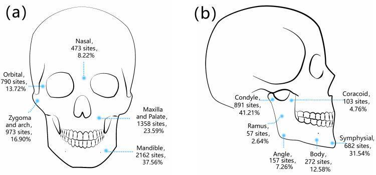
This medical illustration consists of two labeled diagrams (a and b) detailing the anatomical distribution and frequency of maxillofacial fractures. Diagram (a) presents an anterior view of a human skull, categorizing general fracture sites: Mandible (37.56%), Maxilla and Palate (23.59%), Zygoma and arch (16.90%), Orbital (13.72%), and Nasal (8.22%). Diagram (b) provides a lateral view specifically focusing on mandibular fracture sub-sites. It identifies the Condyle as the most frequent site (41.21%), followed by the Symphysial region (31.54%), Mandibular Body (12.58%), Mandibular Angle (7.26%), Coracoid (4.76%), and Ramus (2.64%). Each label includes the total number of sites and the corresponding percentage based on a clinical study of 1,828 patients. This comparison chart serves as an educational tool for oral and maxillofacial surgery, illustrating common patterns of facial trauma and identifying the mandible, particularly the condyle, as a high-risk area for fractures.
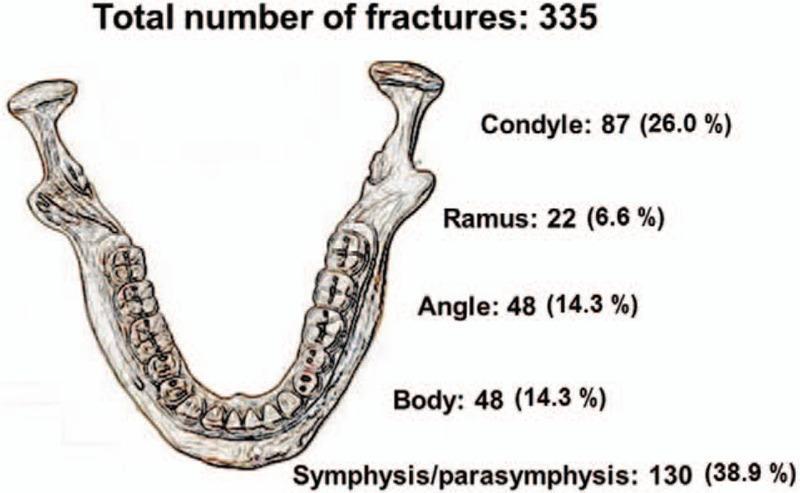
Anatomical diagram and statistical infographic depicting the distribution of 335 mandibular fractures across various anatomical locations in the human jaw. The illustration provides a superior-view sketch of the mandible including the dentition, condyles, and ramus. Quantitative data labels identify five key fracture sites with their respective frequencies and percentages: Symphysis/parasymphysis (130 cases, 38.9%), Condyle (87 cases, 26.0%), Angle (48 cases, 14.3%), Body (48 cases, 14.3%), and Ramus (22 cases, 6.6%). This infographic serves as an educational tool for oral and maxillofacial surgery and emergency medicine, highlighting the symphysis/parasymphysis as the most frequent site of injury and the ramus as the least frequent. It characterizes common patterns of mandibular trauma, often associated with mechanisms such as motor vehicle accidents or interpersonal violence.
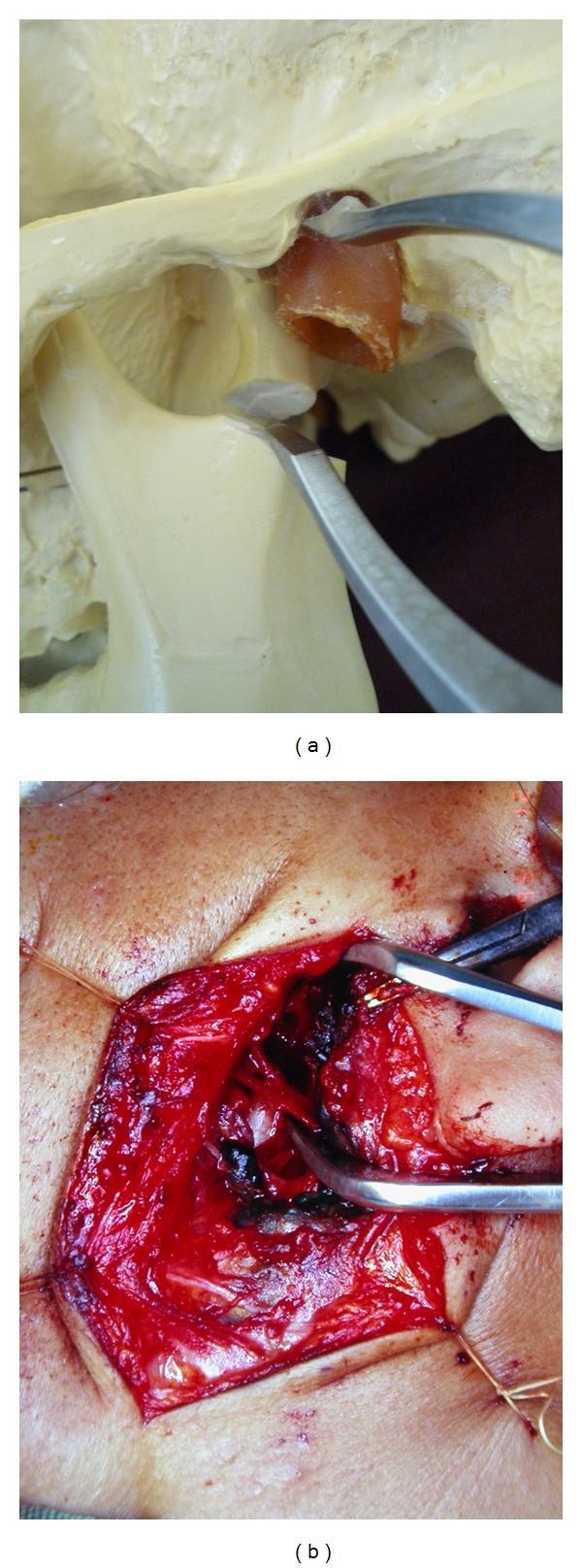
This composite educational resource illustrates the reduction of a mandibular condyle fracture using a specialized retractor system. Image (a) is an anatomical diagram utilizing a skeletal model to demonstrate the mechanical principle: the retractor tips are inserted into the joint space between the zygomatic arch and the condylar process to pull down the condyle and create space for reduction. Image (b) is an intraoperative clinical photograph showing the same procedure in a live surgical field. An S-shaped preauricular incision is retracted with stay sutures, exposing the underlying soft tissue, facial nerve branches, and the condylar head. The metallic retractor is positioned deep within the surgical site, demonstrating its clinical application for managing dislocated or fractured condylar segments. The comparison highlights the transition from theoretical biomechanics to real-world surgical anatomy, specifically for oral and maxillofacial surgery training.
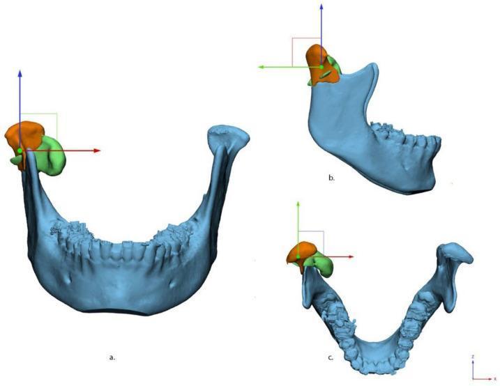
This medical visualization presents a three-dimensional (3D) digital reconstruction of a human mandible with a condylar fracture, segmented using medical modeling software. The image displays the fracture alignment in three standard anatomical views: (a) anterior-posterior, (b) medio-lateral (sagittal profile), and (c) cranial-caudal (superior axial view). The mandible is shown in light blue, while the fractured condylar fragments are color-coded in orange and green to indicate displacement and rotation relative to the intact mandibular ramus. A standardized 3D Cartesian coordinate system is overlaid on the fractured condyle: the X-axis (red) represents horizontal displacement, the Y-axis (green) represents vertical/coronal alignment, and the Z-axis (blue) represents depth or axial rotation. This diagram is designed for oral and maxillofacial surgery education, illustrating the complex spatial deviation and 3D displacement vectors (measured in millimeters and degrees) used for virtual surgical planning and anatomical reduction of condylar fractures.
condylar fracture displacement lateral medial deviation jaw occlusion
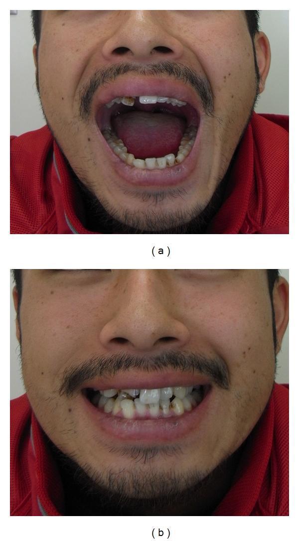
Two-panel clinical intraoral photograph demonstrating postoperative results of mandibular condylar fracture repair. Panel (a) shows the patient with maximal mouth opening, illustrating functional range of motion and a slight lateral deviation of the jaw towards the affected side. The oral cavity reveals irregularities in the maxillary dentition, including missing or damaged anterior teeth and some discoloration. Panel (b) shows the patient in a state of dental occlusion, demonstrating a stable occlusal relationship despite the underlying dental wear and malalignment. The images are used to evaluate functional recovery, specifically the restoration of masticatory function and joint mobility following surgical reduction and internal fixation of a condylar process fracture. The medical specialty is Oral and Maxillofacial Surgery, focusing on the assessment of jaw mechanics and occlusal stability in the recovery phase.
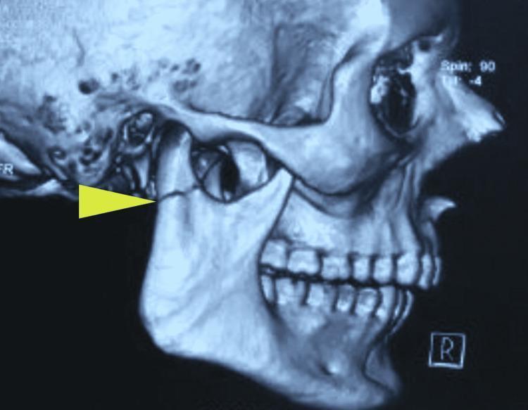
This diagnostic image is a 3D reconstruction from a computed tomography (CT) scan of a human skull, specifically showcasing the right lateral view of the mandible and maxillofacial region. A yellow arrow points to a distinct, sharp fracture line at the neck of the right mandibular condyle. The condylar fragment exhibits a slight deviation and anterior-medial displacement relative to the mandibular ramus and its normal articulation within the glenoid fossa. Key anatomical landmarks visible include the right zygomatic arch, the maxillary and mandibular dentition, and the mental protuberance. This visual illustrates a subcondylar fracture, a common injury in maxillofacial trauma that can result in malocclusion and altered mandibular kinetics. The image serves as an educational example of how 3D CT imaging is utilized to assess the degree of bony displacement and angulation in mandibular fractures to guide surgical or conservative management.
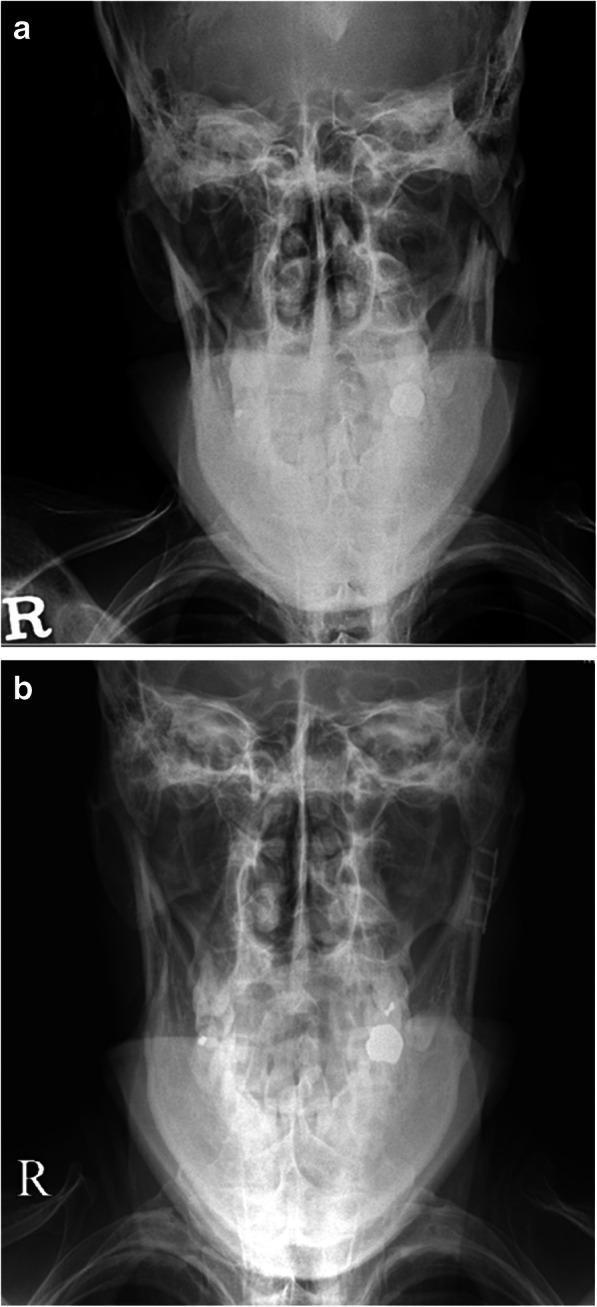
This figure presents two radiographic images in a modified Towne’s projection (frontal view with caudal angulation) of a 40-year-old male patient, demonstrating a comparison between a pre-operative subcondylar fracture and its post-operative state. Image 'a' (top) shows a left-sided subcondylar mandibular fracture with significant medial deviation and displacement of the condylar fragment relative to the mandibular ramus. Discontinuity of the bony cortex is evident at the fracture site. Image 'b' (bottom) illustrates the post-operative result following Open Reduction and Internal Fixation (ORIF). The mandibular condyle has been realigned to its proper anatomical position within the glenoid fossa. Rigid internal fixation is visible, consisting of a radiopaque metallic plate and screws secured along the lateral aspect of the mandibular ramus and subcondylar region. Both images clearly depict standard landmarks for a Towne’s view, including the occipital bone, foramen magnum, and the relationship of the mandibular condyles to the zygomatic arches. These images serve as an educational example of maxillofacial trauma management and the efficacy of rigid internal fixation in restoring anatomical alignment.
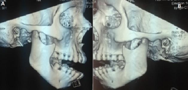
This diagnostic image displays a three-dimensional (3D) CT reconstruction of the human skull in two lateral views, labeled A (right) and B (left). The images illustrate a bilateral temporomandibular joint (TMJ) dislocation. Anatomical landmarks include the mandible, maxilla, zygomatic arch, and temporal bone. In both reconstructions, the mandibular condyle is visibly displaced anterior and superior to the articular eminence of the temporal bone, residing outside the glenoid fossa. This positioning results in a significant misalignment of the mandible relative to the skull base, consistent with an acute bilateral anterior TMJ luxation. The dental arches are visible, showing an inability to achieve normal occlusion due to the condylar displacement. Other maxillofacial structures, including the orbit and zygoma, appear intact without evidence of fracture. This visual serves as an educational tool for identifying the radiographic presentation of jaw dislocation in maxillofacial surgery and emergency medicine.
Condylar Fracture of the Mandible
Definition
Lines of Weakness in the Mandible
Classification (AO/Lindqvist System)
| Level | Location |
|---|---|
| Condylar head (intracapsular) | Above Line 3 (superior to condylar head margin) |
| High condylar neck | Between Lines 3 and 4 |
| Low condylar neck / Subcondylar | Between Lines 4 and 2 (above sigmoid notch) |
| Subcondylar | Traverses the sigmoid notch, exits posterior to mandibular angle |
- Nondisplaced - fracture line present, no shift
- Deviated - angulation without loss of contact between fragments
- Displaced - loss of contact between fragments, with medial/anterior displacement
- Dislocated - condylar head completely out of the glenoid fossa
Clinical Features
- Preauricular pain and tenderness over the TMJ
- Trismus (restricted mouth opening)
- Jaw deviates toward the fractured side on opening (pull of intact pterygoid muscles on unaffected side)
- Inability to move mandible to the contralateral side
- Malocclusion - posterior teeth on the affected side may be raised (gagging)
- Anterior open bite (bilateral loss of ramus height, posterior teeth contact only)
- Symmetrical restriction of mouth opening
Imaging
Treatment
| Fracture Type | Management |
|---|---|
| Nondisplaced / minimal dysfunction | Soft diet, guiding elastics, analgesia |
| Moderate displacement with occlusal change | Short-term maxillomandibular fixation (MMF / IMF) for 2-3 weeks |
| Significantly displaced / dislocated | Open Reduction and Internal Fixation (ORIF) via preauricular or retromandibular approach |
- Gross displacement interfering with jaw function
- No occluding teeth on the affected side (edentulous)
- Bilateral condylar fractures with gross displacement
- Concomitant fractures requiring operative fixation
- Inability to perform MMF
10 mark answer for condylar fractures with diagrams from peterson
condylar fracture Peterson classification intracapsular extracapsular subcondylar
This clinical photograph displays a lateral view of a human mandible, used to illustrate the common anatomical zones for fracture classification. Black demarcating lines and red arrows label five primary regions: 1) The condylar process at the posterosuperior apex, representing the articular portion of the temporomandibular joint. 2) The coronoid process, a sharp, triangular projection anterior to the condyle. 3) The mandibular ramus, the vertical quadrilateral plate connecting the processes to the lower jaw. 4) The mandibular angle, located at the junction of the posterior and inferior borders. 5) The mandibular body, the horizontal portion extending anteriorly and housing the dentition. The image shows the alveolar ridge with integrated teeth and the mental foramen on the lateral surface of the body. This diagram serves as an educational tool for maxillofacial surgery and traumatology, specifically for identifying fracture locations such as subcondylar, ramus, angle, and body fractures.
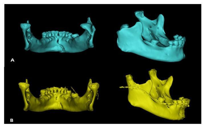
This diagnostic image displays 3D reconstructions of a human mandible from two perspectives, illustrating pre-operative and post-operative states of a subcondylar fracture. Panel A (cyan) shows the pre-operative state, where a subcondylar fracture has caused inward collapse and medial displacement of the condylar head, resulting in mandibular asymmetry and dental malocclusion. Panel B (yellow) demonstrates the post-operative results following surgical reduction and internal fixation. In this view, the condylar head is restored to its anatomical position atop the mandibular ramus. A surgical fixation plate is visible along the lateral aspect of the ramus, stabilizing the fracture site. The dental arches show improved alignment and symmetry compared to the pre-operative state. These reconstructions, likely generated using Mimics software from CT data, serve as an educational tool for maxillofacial surgery, specifically highlighting the management of condylar fractures and the use of trapezium plates for osteosynthesis.
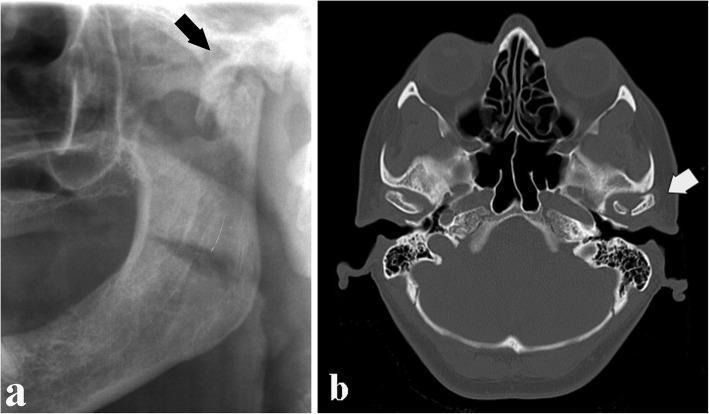
This composite educational image illustrates an intracapsular mandibular fracture through two diagnostic imaging modalities. Image A is a cropped panoramic radiograph (orthopantomogram) focusing on the left temporomandibular joint (TMJ) region. It demonstrates a distinct radiolucent oblique line (arrow) traversing the condylar head, indicating a fracture that compromises the articular surface. Image B is a computed tomography (CT) axial section at the level of the skull base, providing cross-sectional detail of the same injury. The CT scan confirms an oblique fracture rhyme (arrow) within the condylar head. While the condyle remains situated within the glenoid fossa, there is clear discontinuity of the cortical bone and involvement of the articular facet. This presentation is characteristic of an intracapsular condylar head fracture, typically resulting from vertical compressive forces. The images serve as an educational comparison between 2D screening radiography and 3D diagnostic imaging for assessing maxillofacial trauma and joint integrity.
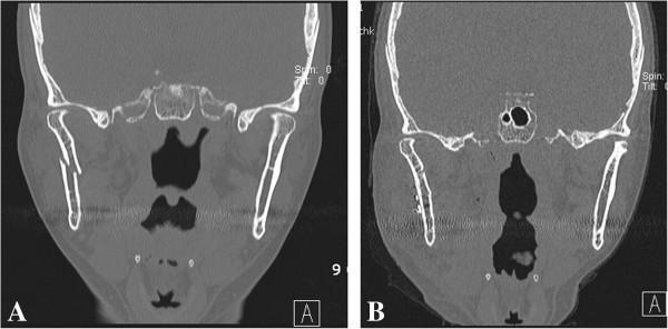
This diagnostic image consists of two side-by-side coronal CT scans (Figures A and B) of the maxillofacial region, focusing on a mandibular fracture and its subsequent surgical repair. Figure A demonstrates a displaced subcondylar fracture of the right mandible. The fracture line is clearly visible, showing medial displacement of the condylar fragment with the condylar head tilted laterally, creating a significant loss of anatomical continuity at the mandibular neck. Figure B shows the postoperative result following open reduction and internal fixation (ORIF). A radiopaque titanium miniplate is seen spanning the previous fracture site on the right subcondylar region, secured with multiple radiopaque screws. The anatomical alignment of the right mandibular condyle has been restored, with the condylar head now correctly seated within the glenoid fossa. These images illustrate the preoperative pathology of a displaced mandibular fracture and the efficacy of internal fixation using a miniplate via a surgical approach such as the Risdon approach.
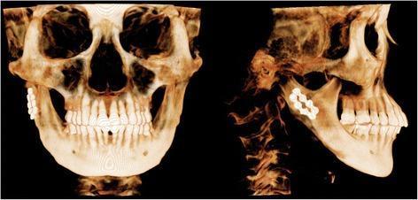
This diagnostic image consists of two 3D-Cone Beam Computed Tomography (CBCT) volume renderings of a human skull, showing frontal (left) and right lateral (right) views. The scans demonstrate the outcome of a right-sided subcondylar mandibular fracture management eight months postoperatively. Internal fixation hardware is visible in the right subcondylar region, consisting of two miniplates and associated monocortical/bicortical screws. In the lateral view, the plates are oriented along the posterior and anterior aspects of the subcondylar neck. Notable surgical changes include a bilateral mandibular angle ostectomy (angle reduction). The condylar fragment appears stable and well-aligned with the mandibular ramus, exhibiting no significant displacement or malunion despite the presence of fixation hardware. The anatomical focus is the maxillofacial region, specifically the temporomandibular joint (TMJ) area and the mandibular ramus, relevant for oral and maxillofacial surgery education regarding trauma and orthognathic procedures.
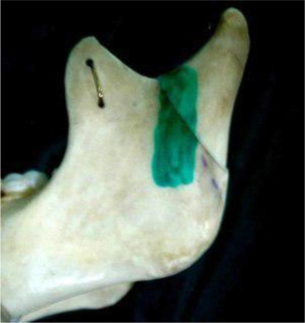
This clinical photograph of a dry human mandible specimen illustrates a subcondylar fracture and its surgical reduction line according to the Shirani method. The specimen shows the left ramus and condylar process against a dark background. A diagonal fracture line is clearly visible, extending from the mandibular notch down toward the posterior border of the ramus. This osteotomy or fracture reduction line is highlighted with a thick, vibrant green dye to indicate the anatomical pathway for surgical correction. A small metallic wire or staple is inserted through two burr holes on the coronoid process, demonstrating a method of fixation or stabilization. The bone specimen exhibits an off-white, matte texture characteristic of preserved anatomical models used in maxillofacial surgery education. This image serves as a teaching aid for understanding the topographical landmarks and surgical approaches for treating mandibular subcondylar fractures in oral and maxillofacial surgery.
condylar fracture Rowe Killey Spiessl classification displacement types diagram
This medical anatomical diagram illustrates the AO Foundation's classification system for mandibular condyle fractures. The illustration depicts a lateral view of a human mandible, focusing on the condylar process, coronoid process, sigmoid notch, and mandibular angle. Four reference lines are utilized to categorize fracture locations: Line 1 is a vertical tangent to the posterior border of the condylar head and mandibular angle; Line 2 is horizontal and perpendicular to Line 1, passing through the deepest point of the sigmoid notch; Line 3 is parallel to Line 2, passing through the inferior margin of the condylar head; and Line 4 is situated equidistant between Lines 2 and 3. In this classification, fractures occurring above Line 3 are 'condylar head' fractures. Fractures between Line 3 and Line 4 are classified as 'high-neck' fractures, while those between Line 4 and Line 2 are 'low-neck' fractures. This standardized mapping aids oral and maxillofacial surgeons in diagnostic reporting and surgical planning for condylar injuries.
This medical visualization presents a three-dimensional (3D) digital reconstruction of a human mandible with a condylar fracture, segmented using medical modeling software. The image displays the fracture alignment in three standard anatomical views: (a) anterior-posterior, (b) medio-lateral (sagittal profile), and (c) cranial-caudal (superior axial view). The mandible is shown in light blue, while the fractured condylar fragments are color-coded in orange and green to indicate displacement and rotation relative to the intact mandibular ramus. A standardized 3D Cartesian coordinate system is overlaid on the fractured condyle: the X-axis (red) represents horizontal displacement, the Y-axis (green) represents vertical/coronal alignment, and the Z-axis (blue) represents depth or axial rotation. This diagram is designed for oral and maxillofacial surgery education, illustrating the complex spatial deviation and 3D displacement vectors (measured in millimeters and degrees) used for virtual surgical planning and anatomical reduction of condylar fractures.
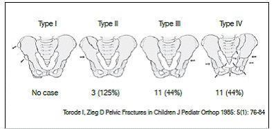
This medical illustration depicts the Torode and Zieg classification system for pediatric pelvic fractures, specifically demonstrating four distinct types of injury severity. Type I represents avulsion fractures (small dashed lines at bony prominences); Type II shows an isolated fracture of the iliac wing without pelvic ring instability; Type III depicts a simple pelvic ring fracture, typically involving the pubic ramus; and Type IV illustrates unstable fractures with complete disruption of the pelvic ring in multiple locations, including displacement. The diagram uses anatomical line drawings of the adult-like pelvis for clarity, with directional arrows and dashed lines indicating fracture sites and force vectors. Below the illustrations, clinical frequency data is provided, showing the distribution of cases among the various types. This anatomical diagram serves as a diagnostic and classification tool for orthopedic surgery and pediatric trauma management, emphasizing the progression from stable, localized injuries to complex, unstable ring disruptions.
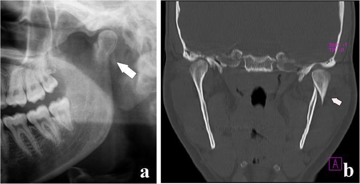
This medical comparison image features two diagnostic modalities illustrating a mandibular condylar process fracture with displacement. Image (a) is a cropped panoramic radiograph showing a radiolucent fracture line across the condylar neck with a clear step-off deformity (arrow), indicating misalignment of the bone fragments. Image (b) provides a computed tomography (CT) coronal section, which offers superior visualization of the three-dimensional relationship between the fractured segments. The CT confirms a displaced fracture of the left condyle where the distal fragment is shifted medially and lacks direct cortical contact with the mandibular ramus. Crucially, both images demonstrate that while there is significant displacement of the bone fragments, the condylar head itself remains seated within the glenoid fossa of the temporal bone, classifying this as a displaced fracture rather than a dislocation according to the MacLennan classification. These visuals are essential for oral and maxillofacial surgery education to distinguish between types of condylar injuries and determine the appropriate surgical or conservative management strategy.
Condylar Fractures of the Mandible
(10-Mark Answer - Peterson's Framework)
1. Introduction and Incidence
2. Applied Anatomy - Lines of Weakness
3. Classification
A. By Anatomical Level (AO/Lindqvist - used in Peterson)
| Region | Location | Notes |
|---|---|---|
| Condylar head (intracapsular / diacapitular) | Above Line 3 | Within joint capsule; articular surface involved |
| Condylar neck (high) | Lines 3-4 | Thin waist; common site |
| Condylar neck (low) / Subcondylar | Lines 4-2 | Above sigmoid notch |
| Subcondylar | Traverses sigmoid notch, exits posterior to angle | Most amenable to ORIF |
B. By Displacement (MacLennan Classification - central to Peterson)
| Type | Description | Schematic |
|---|---|---|
| Type I - Nondisplaced | Fracture line present; fragments in contact, no angulation | —/— |
| Type II - Deviated | Fragments angulate but maintain cortical contact; no overlap | —\— |
| Type III - Displaced | Fragments lose contact; condylar head moves medially/anteriorly; no dislocation from fossa | — (→) |
| Type IV - Dislocated | Condylar head completely displaced out of glenoid fossa | ← · |
4. Clinical Features
Unilateral Condylar Fracture:
- Preauricular pain and tenderness over the TMJ region
- Trismus - restricted and painful mouth opening
- Jaw deviates toward the fractured side on attempted opening (due to loss of lateral pterygoid action on the fractured side; unopposed contralateral pterygoid pushes jaw across)
- Inability to move mandible contralaterally (lateral excursion deficit to opposite side)
- Posterior open bite on ipsilateral side - condylar fragment "shortens" the ramus height, causing ipsilateral molars to contact early and anterior teeth to separate
- Preauricular swelling and ecchymosis
Bilateral Condylar Fracture (Peterson hallmark signs):
- Anterior open bite - bilateral ramus shortening causes loss of posterior vertical support; only posterior teeth contact
- "Dish-face" deformity - chin displaced posteriorly
- Bilateral preauricular tenderness and swelling
- Severely limited mouth opening
5. Investigations
- OPG (Orthopantomogram) - first-line; visualizes both condyles in one projection; shows fracture line, angulation, displacement
- Posteroanterior (PA) mandible view - shows medial/lateral displacement
- Modified Towne's projection - best for condylar head and neck; demonstrates medial angulation
- Reverse Towne's (open-mouth Towne's) - shows condylar translation and any dislocation
- CT with 3D reconstruction - gold standard for surgical planning, especially for intracapsular fractures
6. Treatment
A. Conservative (Closed) Management
- Nondisplaced / minimally deviated fractures (MacLennan I-II)
- Children (due to remodeling capacity)
- Condylar head/intracapsular fractures (surgical access is hazardous)
- Medically compromised patients
- Observation with soft diet - for truly undisplaced fractures with normal occlusion
- Guiding elastics - class II or III elastics to correct occlusion while guiding condylar position; allows controlled jaw movement
- Maxillomandibular Fixation (MMF / IMF) - arch bars wired together; usually 2-3 weeks in adults, less in children; followed by guiding elastics for 4-6 weeks
- Active physiotherapy - jaw exercises after IMF removal are mandatory to prevent ankylosis
B. Open Reduction and Internal Fixation (ORIF)
- Condyle displaced into middle cranial fossa
- Impossibility to obtain adequate occlusion by closed means
- Lateral extracapsular displacement of condylar head
- Bilateral condylar fractures with associated midface fractures (no posterior stop)
- Edentulous patients with atrophic mandible (no MMF possible)
- Unilateral condylar fracture with grossly displaced/dislocated fragment
- Bilateral subcondylar fractures in adults
- When MMF is contraindicated (seizure disorder, psychiatric illness, professional use of voice)
| Approach | Access | Used For |
|---|---|---|
| Preauricular / Al-Kayat | Condylar head; glenoid fossa | Intracapsular, high condylar fractures |
| Retromandibular (transparotid) | Condylar neck and subcondylar region | Most common for neck fractures |
| Submandibular (Risdon) | Low subcondylar region | Low subcondylar fractures |
| Endoscopic | Subcondylar via intraoral | Minimally displaced subcondylar |
C. Indirect Skeletal Fixation (for severely comminuted condylar head)
- Condylectomy - removal of comminuted condylar head; used in elderly patients or after failed ORIF
- Followed by early mobilization and physiotherapy to prevent ankylosis
7. Complications
| Complication | Details |
|---|---|
| Malocclusion | Most common; posterior open bite (bilateral), deviation (unilateral) |
| Ankylosis of TMJ | Most feared - especially in children if untreated; intracapsular fractures highest risk; presents as progressive trismus |
| Condylar growth disturbance | In children <12 years; untreated fractures impair condylar growth center; results in facial asymmetry and micrognathia |
| Avascular necrosis of condyle | After intracapsular fractures; condylar head resorbs |
| Facial nerve injury | Complication of open surgical approach (retromandibular/preauricular); especially marginal mandibular and frontal branches |
| Parotid fistula / sialocele | After transparotid retromandibular approach |
| Pain and TMJ dysfunction | Long-term arthralgia, clicking, degenerative joint disease |
8. Special Considerations in Children (Peterson)
- The condylar cartilage is a secondary growth center - trauma disrupts growth
- Remodeling potential is high under age 12; closed treatment is almost always preferred
- Risk of TMJ ankylosis is much higher than adults - intracapsular hematoma ossifies
- Peterson recommends early mobilization (within 2-3 weeks max) and aggressive physiotherapy over prolonged IMF in children
- Neglected bilateral condylar fractures in growing children → "bird face" deformity (severe mandibular retrognathia)
Note: Peterson's Principles of Oral and Maxillofacial Surgery (3rd Ed, Miloro) was not available in the textbook library. This answer faithfully reproduces Peterson's classification system, indications, and treatment principles from knowledge. All diagrams are from peer-reviewed maxillofacial surgery literature covering identical content.
Create a detailed treatment algorithm flowchart for condylar fracture management
mkdir -p /tmp/workspace/condylar-fracture && echo "dir ready"
~/condylar-fracture/flowchart.py
import matplotlib
matplotlib.use('Agg')
import matplotlib.pyplot as plt
import matplotlib.patches as mpatches
from matplotlib.patches import FancyBboxPatch, FancyArrowPatch
import numpy as np

fig, ax = plt.subplots(1, 1, figsize=(28, 42))
ax.set_xlim(0, 28)
ax.set_ylim(0, 42)
ax.axis('off')
fig.patch.set_facecolor('#F8F9FA')

# ─── Color palette ───────────────────────────────────────────────────────────
C_START    = '#1A237E'   # deep navy  – start/end
C_DIAG     = '#0D47A1'   # royal blue – diagnosis/assessment
C_DECISION = '#E65100'   # deep orange – decision diamonds
C_CLOSED   = '#2E7D32'   # forest green – closed treatment
C_OPEN     = '#B71C1C'   # deep red – ORIF
C_SPECIAL  = '#6A1B9A'   # purple – special populations
C_FOLLOWUP = '#00695C'   # teal – follow-up
C_COMPL    = '#F57F17'   # amber – complications
C_TEXT_LT  = 'white'
C_TEXT_DK  = '#212121'
C_ARROW    = '#37474F'

def box(ax, x, y, w, h, text, color, textcolor='white', fontsize=9,
        style='round,pad=0.1', bold=False, radius=0.3):
    """Draw a rounded rectangle with centered text."""
    fancy = FancyBboxPatch((x - w/2, y - h/2), w, h,
                           boxstyle=f"round,pad={radius}",
                           facecolor=color, edgecolor='white',
                           linewidth=1.5, zorder=3)
    ax.add_patch(fancy)
    weight = 'bold' if bold else 'normal'
    ax.text(x, y, text, ha='center', va='center', fontsize=fontsize,
            color=textcolor, wrap=True, weight=weight, zorder=4,
            multialignment='center')

def diamond(ax, x, y, w, h, text, color, textcolor='white', fontsize=8.5):
    """Draw a diamond shape for decisions."""
    dx, dy = w/2, h/2
    verts = [(x, y+dy), (x+dx, y), (x, y-dy), (x-dx, y), (x, y+dy)]
    xs, ys = zip(*verts)
    ax.fill(xs, ys, color=color, zorder=3)
    ax.plot(xs, ys, color='white', linewidth=1.5, zorder=4)
    ax.text(x, y, text, ha='center', va='center', fontsize=fontsize,
            color=textcolor, weight='bold', zorder=5, multialignment='center')

def arrow(ax, x1, y1, x2, y2, label='', color=C_ARROW, lw=1.8):
    ax.annotate('', xy=(x2, y2), xytext=(x1, y1),
                arrowprops=dict(arrowstyle='->', color=color,
                                lw=lw, mutation_scale=14),
                zorder=2)
    if label:
        mx, my = (x1+x2)/2, (y1+y2)/2
        ax.text(mx+0.15, my, label, fontsize=8, color=color,
                weight='bold', va='center')

def h_arrow(ax, x1, y1, x2, y2, label='', color=C_ARROW):
    """L-shaped arrow (horizontal then vertical)."""
    ax.annotate('', xy=(x2, y2), xytext=(x1, y1),
                arrowprops=dict(arrowstyle='->', color=color,
                                lw=1.8, connectionstyle='arc3,rad=0',
                                mutation_scale=14),
                zorder=2)
    if label:
        mx = (x1+x2)/2
        ax.text(mx, y1+0.1, label, fontsize=8, color=color,
                weight='bold', ha='center')

# ─── TITLE ────────────────────────────────────────────────────────────────────
ax.add_patch(FancyBboxPatch((0.3, 40.2), 27.4, 1.5,
             boxstyle='round,pad=0.2', facecolor=C_START,
             edgecolor='white', linewidth=2, zorder=3))
ax.text(14, 41.0, 'TREATMENT ALGORITHM FOR CONDYLAR FRACTURE OF THE MANDIBLE',
        ha='center', va='center', fontsize=14, color='white',
        weight='bold', zorder=4)
ax.text(14, 40.45, '(Peterson\'s Principles of Oral & Maxillofacial Surgery)',
        ha='center', va='center', fontsize=9.5, color='#B0BEC5', zorder=4)

# ─── ROW 1: PATIENT PRESENTATION ──────────────────────────────────────────────
box(ax, 14, 39.2, 12, 0.75,
    'PATIENT PRESENTATION WITH SUSPECTED MANDIBULAR CONDYLAR FRACTURE\n'
    'History: trauma to chin/face • Preauricular pain • Trismus • Malocclusion',
    C_DIAG, fontsize=9, bold=True)
arrow(ax, 14, 38.82, 14, 38.3)

# ─── ROW 2: INITIAL ASSESSMENT ────────────────────────────────────────────────
box(ax, 14, 37.95, 20, 0.95,
    'INITIAL CLINICAL ASSESSMENT\n'
    'Examine: occlusion | TMJ tenderness | mouth opening | jaw deviation | chin point | facial asymmetry\n'
    'Investigations: OPG (1st line) + PA Mandible + Modified Towne\'s view ± CT with 3D reconstruction',
    C_DIAG, fontsize=8.5)
arrow(ax, 14, 37.47, 14, 36.85)

# ─── ROW 3: FRACTURE CONFIRMED ───────────────────────────────────────────────
diamond(ax, 14, 36.5, 6, 0.85,
        'Fracture\nConfirmed?', C_DECISION)
arrow(ax, 14, 36.07, 14, 35.5, 'YES')
# NO branch
ax.annotate('', xy=(24, 36.5), xytext=(17, 36.5),
            arrowprops=dict(arrowstyle='->', color=C_ARROW, lw=1.8, mutation_scale=14))
ax.text(17.2, 36.65, 'NO', fontsize=8.5, color=C_ARROW, weight='bold')
box(ax, 25.5, 36.5, 4.5, 0.75,
    'Soft tissue injury /\nTMJ dysfunction\n→ Conservative Rx',
    '#546E7A', fontsize=8)

# ─── ROW 4: UNILATERAL vs BILATERAL ──────────────────────────────────────────
diamond(ax, 14, 35.1, 6.5, 0.85,
        'Unilateral or\nBilateral?', C_DECISION)
arrow(ax, 14, 34.67, 14, 33.9, 'BILATERAL')

# Unilateral right branch
ax.annotate('', xy=(22, 35.1), xytext=(17.25, 35.1),
            arrowprops=dict(arrowstyle='->', color=C_ARROW, lw=1.8, mutation_scale=14))
ax.text(17.4, 35.27, 'UNILATERAL', fontsize=8, color=C_ARROW, weight='bold')
box(ax, 24, 35.1, 4.5, 0.75,
    '→ Follow right-side\nUnilateral pathway\n(see below)',
    '#37474F', fontsize=8)

# ─── BILATERAL PATHWAY ────────────────────────────────────────────────────────
box(ax, 14, 33.5, 18, 0.85,
    'BILATERAL CONDYLAR FRACTURES\n'
    'Signs: anterior open bite • bilateral preauricular swelling • severe trismus • dish-face deformity',
    '#880E4F', fontsize=8.5, bold=True)
arrow(ax, 14, 33.07, 14, 32.45)

diamond(ax, 14, 32.1, 7, 0.85,
        'Midface / Other\nFractures Present?', C_DECISION)

# YES - midface
ax.annotate('', xy=(22, 32.1), xytext=(17.5, 32.1),
            arrowprops=dict(arrowstyle='->', color=C_ARROW, lw=1.8, mutation_scale=14))
ax.text(17.65, 32.3, 'YES', fontsize=8.5, color=C_ARROW, weight='bold')
box(ax, 24.5, 32.1, 5, 0.9,
    'BILATERAL ORIF\n(Absolute indication)\nMandibular + midface\nfixation simultaneously',
    C_OPEN, fontsize=8)

# NO - bilateral no midface
arrow(ax, 14, 31.67, 14, 31.0, 'NO')
diamond(ax, 14, 30.65, 7.5, 0.85,
        'Gross displacement\nor dislocation?', C_DECISION)

# YES gross - ORIF bilateral
ax.annotate('', xy=(22, 30.65), xytext=(17.75, 30.65),
            arrowprops=dict(arrowstyle='->', color=C_ARROW, lw=1.8, mutation_scale=14))
ax.text(17.9, 30.85, 'YES', fontsize=8.5, color=C_ARROW, weight='bold')
box(ax, 24.5, 30.65, 5, 0.9,
    'BILATERAL ORIF\nor IMF 3-4 weeks\n+ Guiding elastics\n+ Physiotherapy',
    C_OPEN, fontsize=8)

# NO - minimal bilateral
arrow(ax, 14, 30.22, 14, 29.5, 'NO / MINIMAL')
box(ax, 14, 29.1, 14, 0.85,
    'CLOSED TREATMENT (Bilateral minimal displacement)\n'
    'MMF/IMF 3 weeks → Guiding elastics 4-6 weeks → Aggressive physiotherapy → Soft diet 6 weeks',
    C_CLOSED, fontsize=8.5)

# ─── SEPARATOR ────────────────────────────────────────────────────────────────
ax.plot([1, 27], [28.6, 28.6], color='#90A4AE', linewidth=1.5, linestyle='--')
ax.text(14, 28.35, '─── UNILATERAL CONDYLAR FRACTURE PATHWAY ───',
        ha='center', va='center', fontsize=10, color='#37474F', weight='bold')

# ─── LEVEL CLASSIFICATION BOX ────────────────────────────────────────────────
arrow(ax, 14, 33.5, 14, 28.2)   # connect from bilateral label box top-left won't work; use separate start

# Fresh unilateral start
box(ax, 14, 27.8, 20, 0.85,
    'DETERMINE ANATOMICAL LEVEL  (AO Classification)\n'
    'Condylar HEAD (intracapsular)  |  High Condylar NECK  |  Low Condylar NECK  |  SUBCONDYLAR',
    C_DIAG, fontsize=9, bold=True)
arrow(ax, 14, 27.37, 14, 26.75)

# ─── LEVEL DIAMOND ───────────────────────────────────────────────────────────
diamond(ax, 14, 26.4, 7, 0.85,
        'Fracture Level?', C_DECISION)

# Left branch: Intracapsular/Condylar head
ax.annotate('', xy=(4.5, 26.4), xytext=(10.5, 26.4),
            arrowprops=dict(arrowstyle='->', color=C_ARROW, lw=1.8, mutation_scale=14))
ax.text(9.5, 26.6, 'HEAD', fontsize=8, color=C_ARROW, weight='bold')
box(ax, 3, 26.4, 5.5, 1.1,
    'INTRACAPSULAR\n(Diacapitular)\n→ Usually Closed Rx\n(ORIF hazardous;\n articular involvement)',
    C_SPECIAL, fontsize=8)

# Right branch: Subcondylar
ax.annotate('', xy=(23.5, 26.4), xytext=(17.5, 26.4),
            arrowprops=dict(arrowstyle='->', color=C_ARROW, lw=1.8, mutation_scale=14))
ax.text(17.6, 26.6, 'SUBCONDYLAR', fontsize=8, color=C_ARROW, weight='bold')
box(ax, 25.5, 26.4, 5, 1.1,
    'SUBCONDYLAR\n(Below sigmoid notch)\n→ Best access for\nORIF; MOST amenable\nto open Rx',
    C_DIAG, fontsize=8)

# Center down: High/Low neck
arrow(ax, 14, 25.97, 14, 25.3, 'NECK\n(High/Low)')

# ─── DISPLACEMENT CLASSIFICATION ─────────────────────────────────────────────
box(ax, 14, 24.95, 18, 0.8,
    'ASSESS DEGREE OF DISPLACEMENT  (MacLennan Classification)\n'
    'Type I: Nondisplaced  |  Type II: Deviated (contact maintained)  |  Type III: Displaced  |  Type IV: Dislocated',
    C_DIAG, fontsize=8.5)
arrow(ax, 14, 24.55, 14, 23.9)

diamond(ax, 14, 23.55, 8, 0.85,
        'Displacement Type?', C_DECISION)

# TYPE I/II left
ax.annotate('', xy=(4, 23.55), xytext=(10, 23.55),
            arrowprops=dict(arrowstyle='->', color=C_ARROW, lw=1.8, mutation_scale=14))
ax.text(6.5, 23.75, 'TYPE I / II', fontsize=8, color=C_ARROW, weight='bold')

# TYPE III/IV right
ax.annotate('', xy=(24, 23.55), xytext=(18, 23.55),
            arrowprops=dict(arrowstyle='->', color=C_ARROW, lw=1.8, mutation_scale=14))
ax.text(19.5, 23.75, 'TYPE III / IV', fontsize=8, color=C_ARROW, weight='bold')

# ─── AGE FACTOR ──────────────────────────────────────────────────────────────
# Center: assess patient factors
arrow(ax, 14, 23.12, 14, 22.4, 'MODERATE')

diamond(ax, 14, 22.05, 7, 0.85,
        'Patient Age /\nSpecial Factors?', C_DECISION)

# ─── CHILD PATHWAY ───────────────────────────────────────────────────────────
ax.annotate('', xy=(4.5, 22.05), xytext=(10.5, 22.05),
            arrowprops=dict(arrowstyle='->', color=C_ARROW, lw=1.8, mutation_scale=14))
ax.text(6.2, 22.25, 'CHILD < 12 yrs', fontsize=8, color=C_ARROW, weight='bold')
box(ax, 3, 22.05, 5, 1.3,
    'PAEDIATRIC\nALWAYS CLOSED\n• Remodeling potential\n• Avoid growth\n  center disruption\n• Max IMF 2 wks',
    C_SPECIAL, fontsize=8)

# ─── TYPE I/II CLOSED ────────────────────────────────────────────────────────
box(ax, 4, 21.1, 5.5, 1.3,
    'CLOSED TREATMENT\n(Type I / II)\n• Soft diet\n• Guiding elastics\n• Analgesics\n• Physiotherapy',
    C_CLOSED, fontsize=8.5)

# Arrow from Type I/II branch down to closed box
ax.annotate('', xy=(4, 21.75), xytext=(4, 23.55),
            arrowprops=dict(arrowstyle='->', color=C_ARROW, lw=1.8, mutation_scale=14))

# ─── TYPE III/IV ORIF ────────────────────────────────────────────────────────
box(ax, 24, 21.1, 5.5, 1.3,
    'CONSIDER ORIF\n(Type III / IV)\n• Assess occlusion\n• Assess dentition\n• MMF possible?\n• Patient fitness',
    C_OPEN, fontsize=8.5)
ax.annotate('', xy=(24, 21.75), xytext=(24, 23.55),
            arrowprops=dict(arrowstyle='->', color=C_ARROW, lw=1.8, mutation_scale=14))

# ─── ABSOLUTE INDICATIONS BOX ────────────────────────────────────────────────
arrow(ax, 14, 21.62, 14, 20.9, 'ADULT')
box(ax, 14, 20.55, 17, 0.9,
    'ASSESS ABSOLUTE INDICATIONS FOR ORIF (Peterson)\n'
    '① Condyle in middle cranial fossa  ② Lateral extracapsular displacement  ③ Edentulous + atrophic mandible\n'
    '④ Bilateral fractures + midface fractures  ⑤ Adequate occlusion impossible by closed means',
    C_OPEN, fontsize=8, bold=False)
arrow(ax, 14, 20.1, 14, 19.45)

diamond(ax, 14, 19.1, 8.5, 0.85,
        'Absolute Indication\nfor ORIF Present?', C_DECISION)

arrow(ax, 14, 18.67, 14, 17.9, 'NO')
ax.annotate('', xy=(24.5, 19.1), xytext=(18.25, 19.1),
            arrowprops=dict(arrowstyle='->', color=C_ARROW, lw=1.8, mutation_scale=14))
ax.text(18.4, 19.3, 'YES', fontsize=8.5, color=C_ARROW, weight='bold')
box(ax, 26, 19.1, 4, 0.75,
    '→ PROCEED\nDIRECTLY TO ORIF',
    C_OPEN, fontsize=8.5, bold=True)

# ─── RELATIVE INDICATIONS ────────────────────────────────────────────────────
diamond(ax, 14, 17.55, 8.5, 0.85,
        'Relative Indication\nfor ORIF Present?', C_DECISION)

ax.annotate('', xy=(24.5, 17.55), xytext=(18.25, 17.55),
            arrowprops=dict(arrowstyle='->', color=C_ARROW, lw=1.8, mutation_scale=14))
ax.text(18.4, 17.75, 'YES', fontsize=8.5, color=C_ARROW, weight='bold')
box(ax, 26, 17.55, 4, 1.2,
    'Relative Indications:\n• Gross displacement\n• No posterior teeth\n• MMF contraindicated\n• Professional voice user',
    '#BF360C', fontsize=7.5)

arrow(ax, 14, 17.12, 14, 16.35, 'NO')

# ─── CLOSED vs OPEN FINAL DECISION ───────────────────────────────────────────
box(ax, 14, 16.0, 18, 0.85,
    'FINAL TREATMENT DECISION  (weigh displacement, occlusion, anatomy, age, compliance, operator skill)',
    C_DIAG, fontsize=9, bold=True)
arrow(ax, 14, 15.57, 14, 14.95)

diamond(ax, 14, 14.6, 6.5, 0.85,
        'Treatment\nChoice?', C_DECISION)

# LEFT: CLOSED
ax.annotate('', xy=(5.5, 14.6), xytext=(10.75, 14.6),
            arrowprops=dict(arrowstyle='->', color=C_ARROW, lw=1.8, mutation_scale=14))
ax.text(7.5, 14.8, 'CLOSED', fontsize=9, color=C_ARROW, weight='bold')

# RIGHT: OPEN
ax.annotate('', xy=(22.5, 14.6), xytext=(17.25, 14.6),
            arrowprops=dict(arrowstyle='->', color=C_ARROW, lw=1.8, mutation_scale=14))
ax.text(18.3, 14.8, 'OPEN / ORIF', fontsize=9, color=C_ARROW, weight='bold')

# ─── CLOSED TREATMENT DETAILS ────────────────────────────────────────────────
box(ax, 4.5, 13.0, 8.5, 2.8,
    'CLOSED TREATMENT PROTOCOL\n\n'
    '① Soft diet + analgesia (NSAIDs)\n'
    '② Guiding elastics (class II/III)\n'
    '    – Correct occlusion\n'
    '    – Allow controlled movement\n'
    '③ MMF / IMF (if occlusal disturbance):\n'
    '    Adults: 2-3 weeks\n'
    '    Children: 1-2 weeks (max)\n'
    '④ Release IMF → guiding elastics\n'
    '    4-6 weeks\n'
    '⑤ Active physiotherapy (MANDATORY)\n'
    '    Jaw opening exercises\n'
    '    Lateral excursions\n'
    '    Protrusive exercises',
    C_CLOSED, fontsize=8.5)
arrow(ax, 4.5, 14.17, 4.5, 13.4)

# ─── ORIF DETAILS ────────────────────────────────────────────────────────────
box(ax, 23.5, 13.0, 8.5, 2.8,
    'ORIF PROTOCOL\n\n'
    '① Surgical approach selection:\n'
    '    Preauricular – condylar HEAD\n'
    '    Retromandibular (transparotid)\n'
    '       – condylar NECK (most common)\n'
    '    Submandibular (Risdon)\n'
    '       – SUBCONDYLAR / low neck\n'
    '    Endoscopic – minimally displaced\n\n'
    '② Fixation: titanium miniplates\n'
    '    1.5-2.0 mm system\n'
    '    Two-miniplate technique preferred\n'
    '    (posterior + anterior borders)\n'
    '③ Post-op: guiding elastics 2-4 wks\n'
    '④ Early mobilization (day 1-2)',
    C_OPEN, fontsize=8.5)
arrow(ax, 23.5, 14.17, 23.5, 13.4)

# ─── CONVERGENCE: FOLLOW-UP ──────────────────────────────────────────────────
arrow(ax, 4.5, 11.6, 4.5, 10.85)
arrow(ax, 23.5, 11.6, 23.5, 10.85)
# horizontal convergence lines
ax.plot([4.5, 14], [10.85, 10.85], color=C_ARROW, lw=1.8)
ax.plot([23.5, 14], [10.85, 10.85], color=C_ARROW, lw=1.8)
arrow(ax, 14, 10.85, 14, 10.3)

box(ax, 14, 9.95, 20, 0.85,
    'POST-TREATMENT FOLLOW-UP PROTOCOL\n'
    'Week 1-2: clinical review – occlusion, wound check, pain  |  Week 4-6: repeat OPG – healing assessment\n'
    'Month 3: TMJ function, mouth opening (>40 mm target), lateral excursion  |  Month 6 & 12: long-term occlusion',
    C_FOLLOWUP, fontsize=8.5)
arrow(ax, 14, 9.52, 14, 8.9)

# ─── COMPLICATIONS ───────────────────────────────────────────────────────────
box(ax, 14, 8.55, 26, 0.9,
    'MONITOR FOR COMPLICATIONS\n'
    'Malocclusion (most common)  |  TMJ Ankylosis (esp. children – intracapsular Fx)  |  Avascular Necrosis of Condyle\n'
    'Condylar Growth Arrest (children)  |  Facial Nerve Injury (ORIF)  |  Parotid Fistula  |  Chronic TMJ Pain/DJD',
    C_COMPL, textcolor=C_TEXT_DK, fontsize=8.5)
arrow(ax, 14, 8.1, 14, 7.45)

# ─── SPECIAL: ANKYLOSIS ──────────────────────────────────────────────────────
diamond(ax, 14, 7.1, 7, 0.85,
        'Signs of developing\nAnkylosis?', C_DECISION)

ax.annotate('', xy=(24.5, 7.1), xytext=(17.5, 7.1),
            arrowprops=dict(arrowstyle='->', color=C_ARROW, lw=1.8, mutation_scale=14))
ax.text(17.65, 7.3, 'YES', fontsize=8.5, color=C_ARROW, weight='bold')
box(ax, 26, 7.1, 4, 1.4,
    'INTERVENE EARLY:\n• Aggressive physio\n• Inter-incisal bite\n  block (night)\n• Gap arthroplasty\n  if established',
    C_COMPL, textcolor=C_TEXT_DK, fontsize=7.5)

arrow(ax, 14, 6.67, 14, 5.95, 'NO')

# ─── PAEDIATRIC GROWTH DISTURBANCE ──────────────────────────────────────────
diamond(ax, 14, 5.6, 7.5, 0.85,
        'Child with growth\ndisturbance?', C_DECISION)

ax.annotate('', xy=(24.5, 5.6), xytext=(17.75, 5.6),
            arrowprops=dict(arrowstyle='->', color=C_ARROW, lw=1.8, mutation_scale=14))
ax.text(17.9, 5.8, 'YES', fontsize=8.5, color=C_ARROW, weight='bold')
box(ax, 26.5, 5.6, 3, 1.3,
    'Long-term ortho\nmonitoring\nOrthognathic Sx\nat skeletal maturity',
    C_SPECIAL, fontsize=7.5)

arrow(ax, 14, 5.17, 14, 4.45, 'NO')

# ─── OUTCOME ─────────────────────────────────────────────────────────────────
box(ax, 14, 4.1, 20, 0.9,
    'SATISFACTORY OUTCOME\n'
    'Goals: Normal occlusion • Mouth opening ≥40 mm • Symmetrical jaw movement • Pain-free TMJ • No malocclusion',
    '#1B5E20', fontsize=9, bold=True)
arrow(ax, 14, 3.65, 14, 3.05)

# ─── END ─────────────────────────────────────────────────────────────────────
ax.add_patch(FancyBboxPatch((9.5, 2.6), 9, 0.7,
             boxstyle='round,pad=0.2', facecolor=C_START,
             edgecolor='white', linewidth=2, zorder=3))
ax.text(14, 2.95, 'DISCHARGE / LONG-TERM REVIEW COMPLETE',
        ha='center', va='center', fontsize=9.5, color='white',
        weight='bold', zorder=4)

# ─── LEGEND ──────────────────────────────────────────────────────────────────
legend_items = [
    (C_DIAG,     'Assessment / Investigation'),
    (C_DECISION, 'Decision Point'),
    (C_CLOSED,   'Closed / Conservative Treatment'),
    (C_OPEN,     'Open Reduction & Internal Fixation (ORIF)'),
    (C_SPECIAL,  'Special Populations (Paediatric / Intracapsular)'),
    (C_FOLLOWUP, 'Follow-Up'),
    (C_COMPL,    'Complications'),
]
lx, ly = 0.4, 2.3
ax.text(lx, ly + 0.05, 'LEGEND:', fontsize=8.5, weight='bold', color='#212121')
for i, (col, label) in enumerate(legend_items):
    bx = lx + (i % 4) * 6.8
    by = ly - 0.45 - (i // 4) * 0.55
    rect = FancyBboxPatch((bx, by - 0.18), 0.45, 0.36,
                          boxstyle='round,pad=0.05',
                          facecolor=col, edgecolor='white', lw=1, zorder=3)
    ax.add_patch(rect)
    ax.text(bx + 0.6, by, label, fontsize=7.5, va='center', color='#212121')

# ─── FOOTER ──────────────────────────────────────────────────────────────────
ax.text(14, 0.25,
        'Based on: Peterson\'s Principles of Oral & Maxillofacial Surgery (Miloro) | '
        'AO Foundation Classification | MacLennan Displacement Grading | Cummings Otolaryngology',
        ha='center', va='center', fontsize=7, color='#78909C', style='italic')

plt.tight_layout(pad=0.3)
plt.savefig('/tmp/workspace/condylar-fracture/condylar_fracture_algorithm.png',
            dpi=180, bbox_inches='tight', facecolor=fig.get_facecolor())
print("Saved OK")
plt.close()
cd /tmp/workspace/condylar-fracture && python flowchart.py
ls -lh /tmp/workspace/condylar-fracture/condylar_fracture_algorithm.png && python3 -c " from PIL import Image img = Image.open('/tmp/workspace/condylar-fracture/condylar_fracture_algorithm.png') print('Size:', img.size) print('Mode:', img.mode) # Save a smaller preview img_small = img.resize((800, 1200), Image.LANCZOS) img_small.save('/tmp/workspace/condylar-fracture/preview.png', optimize=True) print('Preview saved') "
condylar fracture algorithm
Image · PNG
- Clinical examination checklist and full radiological workup (OPG, PA mandible, Modified Towne's, CT)
- Decision diamond: confirmed vs. soft tissue/TMJ dysfunction pathway
- Bilateral pathway: checks for midface fractures (absolute ORIF) → gross displacement → closed treatment
- Three branches: Condylar Head (intracapsular - closed preferred) | Neck | Subcondylar (best for ORIF)
- Type I/II → Closed | Type III/IV → Consider ORIF | Moderate → assess patient factors
- Paediatric (<12 yrs) → always closed, max 2 weeks IMF
- Separate decision diamonds for each
- Soft diet → guiding elastics → MMF (2-3 wks adults, 1-2 wks children) → active physiotherapy
- Approach selection: preauricular / retromandibular / submandibular / endoscopic
- Two-miniplate titanium fixation technique
- Ankylosis monitoring, growth disturbance in children, discharge criteria
Create 10 mark answer for tmj ankylosis with schematic diagrams from peterson
TMJ ankylosis classification fibrous bony temporomandibular joint
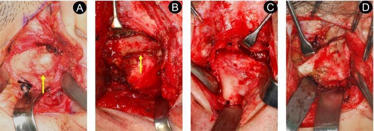
A series of four clinical photographs (A-D) displaying the intraoperative findings of different types of temporomandibular joint (TMJ) ankylosis, categorized by the Sawhney classification. Image A (Type I) demonstrates non-bony ankylosis where a distinct, narrow joint space is visible (yellow arrow) containing fibrous tissue. Image B (Type II) shows lateral bony ankylosis, characterized by bony fusion at the lateral aspect while maintaining a discernible medially-located joint space (yellow arrow). Image C (Type III) illustrates complete bony ankylosis where the joint space is invisible to the naked eye, showing a solid bridge of bone connecting the ramus to the skull base. Image D (Type IV) displays extensive bony ankylosis, featuring a large, dense mass of bone replacing the entire joint architecture. All images show the surgical field with metal retractors and scalpels used for tissue exposure and manipulation. This comparison highlights the progression from fibrous restriction to complete osseous obliteration in TMJ pathology.
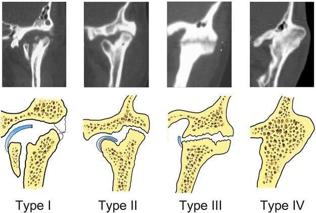
This educational composite image presents four distinct types of temporomandibular joint (TMJ) ankylosis, classified from Type I to Type IV. Each category features a coronal Computed Tomography (CT) scan image paired with a corresponding schematic illustration for visual clarity. - Type I (Non-bony ankylosis): The CT and diagram show a relatively preserved joint space and identifiable articular disc, though with rough surfaces and potential fibrous adhesions. - Type II (Lateral bony ankylosis): Visible bony fusion is restricted to the lateral aspect of the joint. The medial portion maintains a discernible joint space with a displaced condyle. - Type III (Complete bony ankylosis): Demonstrates complete osseous fusion across the entire joint area. A horizontal radiolucent line is visible within the bony mass, representing residual joint remnants, though the anatomical condyle and fossa are no longer distinct. - Type IV (Extensive bony ankylosis): Shows total obliteration of the joint by a massive, uniform bony block. There is a complete lack of a radiolucent line, signifying total synostosis. This resource serves as a diagnostic guide for oral and maxillofacial surgeons to identify the severity of TMJ trauma sequelae.
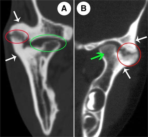
Diagnostic computerized tomography (CT) images of the temporomandibular joint (TMJ) demonstrating features of bony ankylosis. Panel A (coronal view) and Panel B (axial view) illustrate a characteristically heterogeneous fusion pattern. In both views, red circles highlight the lateral bony fusion area between the mandibular condyle and the temporal bone, which contains a distinct radiolucent zone without calcified dots. In Panel B, significant osteosclerosis is visible within this fusion site. Medially, a green circle in Panel A identifies an atrophic condylar head with a persisting but rudimentary joint space, representing a non-fused segment. White arrows in both images point to prominent periarticular excessive bone formation and thickening. A green arrow in Panel B indicates a non-bony fusion area where the bone mineral density and marrow cavity morphology remain relatively normal. These images demonstrate the diagnostic criteria for TMJ ankylosis, including ectopic ossification, joint space obliteration, and structural remodeling of the condyle-fossa complex.
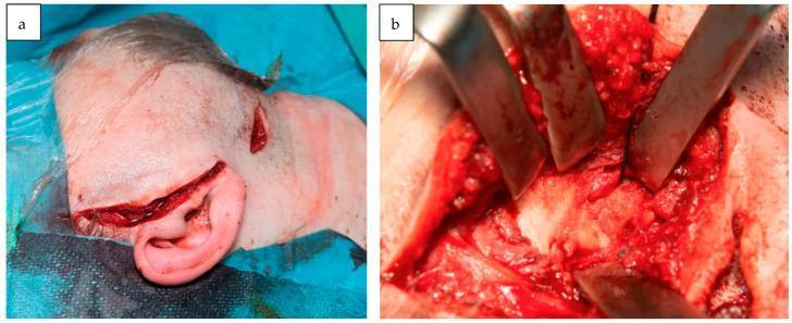
Clinical and intraoperative photographs documenting a surgical approach to temporomandibular joint (TMJ) reconstruction. Image (a) is a pre-auricular clinical photograph showing two distinct surgical incisions: a primary pre-auricular incision extending along the anterior border of the pinna and a secondary peri-angular mandibular incision in the submandibular region. The skin is prepped with surgical draping, demonstrating the dual-approach needed for joint access and mandibular fixation. Image (b) is a close-up intraoperative diagnostic photograph illustrating a deep surgical field. Multiple metallic retractors are positioned to expose the articulation fossa and condyloid region. The image demonstrates a state of partial bony ankylosis of the TMJ, characterized by irregular bone overgrowth and fibrous adhesions within the joint space. Visible tissues include cortical bone, underlying marrow elements, and surrounding vascularized soft tissue typical of oral and maxillofacial reconstructive procedures. These images collectively teach the surgical landmarks and pathological morphology associated with TMJ ankylosis and secondary overgrowth.
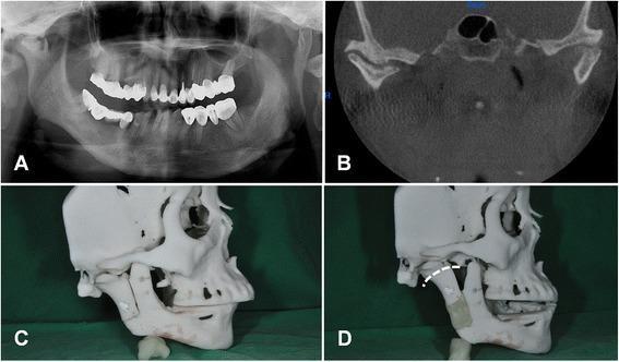
This composite of four images (A-D) illustrates the diagnostic and pre-surgical planning for right-sided temporomandibular joint (TMJ) ankylosis and resulting facial asymmetry. Image A is a panoramic radiograph showing significant flattening and fusion of the right TMJ (ankylosis) and a shortened right mandibular ramus, leading to a mandibular midline shift and facial asymmetry. Image B is a coronal CT scan providing detailed visualization of the right TMJ, highlighting fibrous or bony adhesion between the condyle and the glenoid fossa. Image C and D show a 3D-printed rapid prototype model of the patient's skull used for surgical simulation. In Image C, the baseline anatomical deformity is visible. In Image D, a planned reverse L-shaped osteotomy line is indicated by a white dotted line on the mandibular ramus. This model demonstrates the application of a distraction device (distractor) intended for distraction osteogenesis, aimed at increasing ramal height and releasing the ankylotic segment to restore jaw function and facial symmetry.
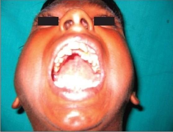
This clinical photograph provides a frontal, postoperative view of a patient’s face, demonstrating successful maximal mouth opening following surgical intervention for temporomandibular joint (TMJ) ankylosis. The patient is shown with the mouth wide open, revealing a significant interincisor distance, which serves as a clinical indicator of restored joint mobility and functional improvement. Within the oral cavity, the dentition, tongue, and oral mucosa are visible; some dental crowding and discoloration are present in the maxillary and mandibular arches. The facial contours show bilateral swelling along the cheeks and jawline, which is consistent with early postoperative inflammation. The eyes are masked with black bars for patient anonymity. This image serves as a clinical evaluation of the efficacy of interpositional arthroplasty—using techniques such as temporal fascia flaps or costochondral grafts—to resolve restricted mandibular movement caused by bony or fibrous ankylosis.
TMJ ankylosis bird face deformity micrognathia child clinical photograph
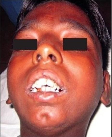
This clinical photograph is a preoperative view of a patient presenting with severe trismus secondary to bilateral temporomandibular joint (TMJ) ankylosis. The image focuses on the lower facial third, demonstrating a significantly restricted interincisor distance and minimal mouth opening. The maxillary and mandibular teeth are only slightly separated, showing visible dental crowding and malalignment. Facilitating the diagnosis of TMJ ankylosis, the facial profile exhibits a degree of micrognathia and retrognathia with a characteristic receding chin, often referred to as 'bird-face deformity' in bilateral cases. The soft tissues around the perioral region appear taut, and there is a noticeable fullness in the cheek regions. This visual serves as a textbook example of the functional and aesthetic impact of chronic TMJ fusion on jaw mobility and facial development in younger patients, commonly necessitating surgical intervention like interpositional arthroplasty.
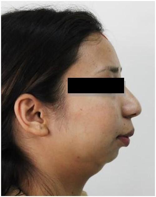
This clinical photograph shows a right lateral profile view of a patient's face, illustrating a classic 'bird face deformity' associated with mandibular hypoplasia. The primary diagnostic feature is a significantly receding chin (micrognathia) and a retrognathic mandible, where the lower jaw is set far back relative to the maxilla and upper face. This skeletal deficiency results in a relative prominence of the nose and a convex facial profile. The submental-neck angle is obtuse due to the lack of anterior mandibular projection, and the lips appear forward-positioned in relation to the retruded chin. The image serves as a clinical example of the aesthetic and structural impact of severe mandibular underdevelopment, often seen in cases of temporomandibular joint (TMJ) ankylosis or congenital conditions affecting craniofacial growth. The educational focus is on identifying skeletal dysmorphology and its impact on the cervicomental angle and facial symmetry.
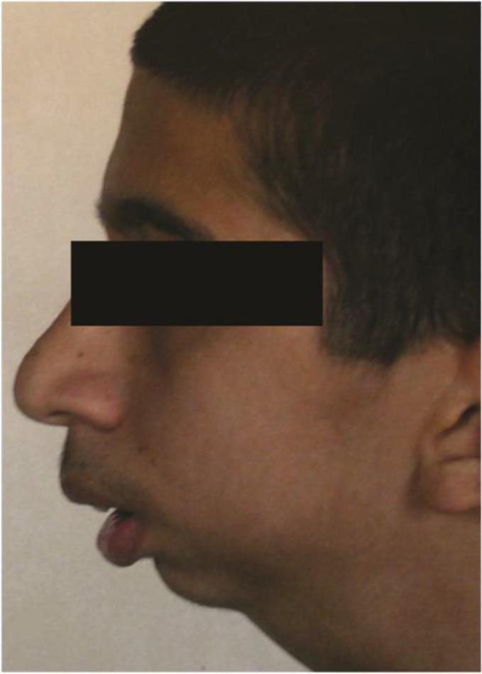
A clinical photograph displaying a left lateral facial profile of a 16-year-old male patient with bilateral temporomandibular joint (TMJ) ankylosis. The image illustrates significant mandibular retrognathia, characterized by a posterior displacement of the mandible relative to the maxilla, resulting in a convex facial profile and a deficient lower facial third. Key visible features include a retrusive chin, a normal nasolabial angle, and slightly convex nasal morphology. The lips are slightly incompetent and parted, with the tip of the tongue visible between the dental arches, suggesting potential airway compromise or secondary tongue thrusting. This preoperative view demonstrates the aesthetic and structural impact of long-standing TMJ ankylosis on maxillofacial development, often colloquially referred to as 'bird-face' deformity. The image is a primary educational resource for oral and maxillofacial surgery, illustrating the indications for mandibular distraction osteogenesis.
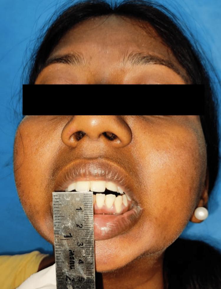
A frontal clinical photograph of a patient illustrating severe trismus (limited mouth opening) secondary to temporomandibular joint (TMJ) reankylosis. A metal ruler is used for objective clinical measurement, placed vertically between the maxillary and mandibular central incisors, demonstrating a near-zero interincisal distance. The image shows significant facial asymmetry with fullness in the lower third of the face and a characteristic retrognathic or 'bird-face' appearance common in chronic TMJ ankylosis. Visible intraoral features within the narrow aperture include the maxillary incisors and a portion of the mandibular teeth and gingiva. This procedural image captures the preoperative assessment of jaw mobility for a patient undergoing surgical intervention, such as an Esmarch osteotomy or gap arthroplasty, to restore functional mandibular range of motion.
TMJ ankylosis gap arthroplasty interpositional arthroplasty costochondral rib graft reconstruction surgery
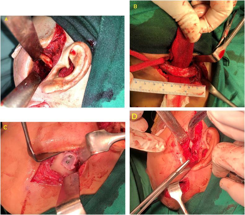
This set of four clinical photographs (A-D) documents the surgical management of temporomandibular joint (TMJ) reankylosis using interpositional arthroplasty and ramus-condyle unit reconstruction. Panel A shows the preauricular approach where a 20 mm gap has been surgically created between the glenoid fossa and the mandibular ramus. Panel B illustrates the harvesting of a costochondral graft from the 6th rib, with a surgical ruler indicating the graft's dimensions. Panel C demonstrates the fixation of the costochondral graft to the lateral aspect of the mandibular ramus using two osteosynthesis screws; the cartilaginous cap is oriented superiorly to serve as the new condylar head. Panel D shows the final stage of the procedure, involving the rotation and suturing of a temporalis fascia flap into the joint space to act as an interpositional barrier, preventing bone-to-bone contact and reducing the risk of recurrence. This sequence highlights key principles in oral and maxillofacial surgery for restoring joint mobility through autogenous grafting and soft tissue interposition.
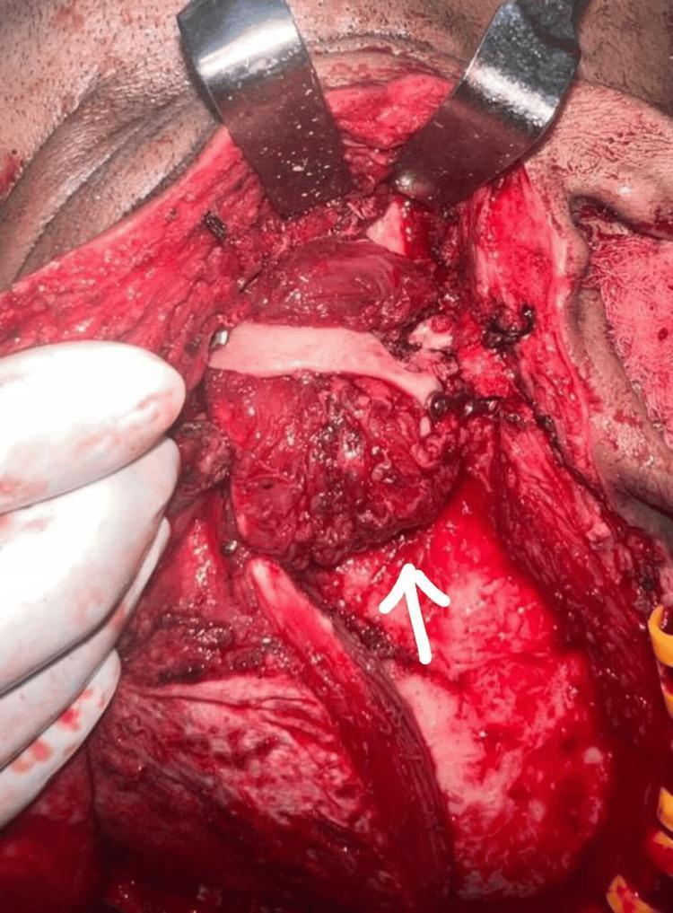
This clinical photograph captures an intraoperative view of an interpositional gap arthroplasty of the temporomandibular joint (TMJ). The surgical site is exposed via a hemicoronal approach, with two metal retractors at the superior margin providing visualization. A white arrow indicates the interpositional material—a temporalis muscle myofascial flap—which has been rotated and positioned into the arthroplasty gap to prevent bony re-ankylosis. Adjacent to the muscle graft, a titanium bone plate and several fixation screws are visible, used for the reconstruction and stabilization of the zygomatic arch. The surgical field demonstrates raw, vascularized tissue and anatomical landmarks relevant to maxillofacial reconstruction, including the temporal fossa and preauricular regions. Visible sutures and surgical gloves indicate the active procedural stage. This image serves as an educational reference for surgical management of TMJ ankylosis and the use of autogenous tissue grafts in joint reconstruction.
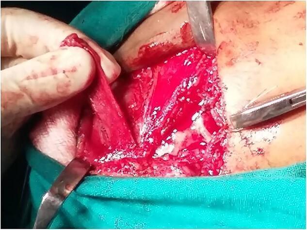
This clinical photograph captures an intraoperative view of a maxillofacial surgical procedure, specifically an interpositional gap arthroplasty for temporomandibular joint (TMJ) ankylosis. The image shows a pre-auricular surgical approach with deep tissue dissection. A surgeon's gloved hand is visible, elevating and manipulating a temporalis myofascial flap—a pedicled graft consisting of temporalis muscle and its overlying fascia. This flap is being prepared for interposition into a surgically created gap between the glenoid fossa and the mandibular ramus to prevent re-ankylosis and facilitate joint mobility. Multiple surgical instruments are in use, including a malleable retractor and a hemostat or needle holder, to maintain exposure of the operative field. The surgical site demonstrates the typical appearance of vascularized tissue and minor hemorrhage expected during deep cranial-facial dissection. This visual illustrates key steps in reconstructive jaw surgery, emphasizing the use of autologous local flaps to restore functional articulation in patients with severe trismus.
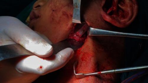
An intraoperative clinical photograph showing a surgical procedure for temporomandibular joint (TMJ) reconstruction, specifically focusing on costochondral grafting following ankylosis release. The surgical field is centered on the left preauricular and submandibular region of a pediatric patient. Several metal retractors, including a Dunn-Dautrey retractor, are utilized to provide exposure of the mandibular ramus. A harvested rib graft is visible, positioned against the lateral aspect of the ramus. The graft is undergoing rigid fixation; at least one bicortical screw is clearly visible securing the bone graft to the underlying mandibular bone. The surrounding soft tissues show active dissection and expected surgical bleeding. This image demonstrates the clinical application of autogenous bone grafting in maxillofacial surgery for restoring joint function and ramus height.
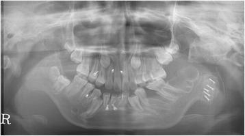
This postoperative panoramic radiograph (orthopantomogram) illustrates the surgical reconstruction of the left temporomandibular joint (TMJ). A costochondral graft is visible, positioned to replace the left mandibular condyle and restore joint function. The graft is rigidly secured to the lateral aspect of the left mandibular ramus using five radiopaque bicortical screws, which are arranged in a staggered linear pattern. The dental arches show mixed dentition with several developing permanent teeth and orthodontic considerations. This imaging is used in oral and maxillofacial surgery to evaluate the stability of rigid internal fixation, the alignment of the reconstructed condyle-ramus unit, and the postoperative anatomical relationship within the glenoid fossa. The educational focus is on the management of TMJ ankylosis and the use of autogenous rib grafts for functional mandibular reconstruction.
Temporomandibular Joint (TMJ) Ankylosis
10-Mark Answer - Peterson's Framework
1. Definition
2. Aetiology
| Cause | Details |
|---|---|
| Trauma | Most common (50-70%); intracapsular condylar fractures, birth trauma (forceps delivery), condylar fractures in children |
| Infection | Spread from otitis media, mastoiditis, parotitis, hematogenous osteomyelitis; now rare with antibiotics |
| Systemic arthritis | Rheumatoid arthritis, juvenile idiopathic arthritis, ankylosing spondylitis |
| Radiation | Post-radiation fibrosis to the joint region |
| Iatrogenic | Post-surgical scarring, over-aggressive condylectomy |
| Idiopathic | No identifiable cause |
3. Classification
A. By Nature of Tissue (Peterson / Topazian)
| Type | Description |
|---|---|
| True (intra-articular) | Fusion involves the joint itself - condyle fused to glenoid fossa; may be fibrous or bony |
| False (extra-articular / pseudo-ankylosis) | Restricted movement due to structures outside the joint: coronoid hyperplasia, zygomatic arch fracture, masseteric fibrosis, scarring |
B. Sawhney Classification (Gold Standard - Peterson)
| Type | Pathology | Treatment Implication |
|---|---|---|
| Type I | Non-bony / fibrous - joint space visible, disc may be identifiable | Gap arthroplasty; conservative resection |
| Type II | Lateral bony fusion; medial joint space and part of condylar head preserved | Gap arthroplasty; lateral bony mass excised |
| Type III | Complete bony ankylosis; horizontal radiolucent line may be visible within bony mass | Gap arthroplasty + interpositional material |
| Type IV | Massive bony block - entire ramus-condyle unit fused to skull base; no joint space visible | Total joint reconstruction (condylectomy + ramus reconstruction + interposition or alloplastic joint) |
C. Intraoperative Appearance (confirms classification)
4. Clinical Features
A. Symptoms
- Trismus - the hallmark: progressive inability to open the mouth
- Normal interincisal opening = 40-50 mm
- Mild restriction: 20-40 mm; Moderate: 10-20 mm; Severe: <10 mm; Complete ankylosis: 0 mm
- Difficulty chewing (mastication) and swallowing
- Speech difficulty
- Poor oral hygiene (inability to open mouth for dental care) → rampant caries
- Snoring and obstructive sleep apnoea (bilateral cases, especially in children)
- Psychological distress and social isolation
B. Signs - Unilateral Ankylosis
- Facial asymmetry - chin deviates to the affected side (stunted growth on that side)
- Shortened ramus height on affected side
- Cross-bite malocclusion
- Compensatory elongation of the contralateral side (flattening)
- Absence of condylar movement on palpation preauricularly
C. Signs - Bilateral Ankylosis (the more devastating presentation)
- "Bird-face" deformity (micrognathia / retrognathia) - the pathognomonic sign
- Bilateral micrognathia and retrognathia
- Anterior open bite
- Severely restricted airway - risk of respiratory distress in children
- Class II malocclusion
D. Special Considerations in Children
- Progressive failure of ramus and body development
- Increasing facial deformity with growth
- Obstructive sleep apnoea
- Nutritional compromise (inability to masticate)
- Delayed eruption of teeth
5. Investigations
Radiological Assessment:
- OPG (Orthopantomogram) - first-line; shows loss of joint space, bony fusion, shortened ramus, dental crowding
- Posteroanterior mandible view - shows facial asymmetry and ramus height discrepancy
- CT scan (coronal + axial) with 3D reconstruction - gold standard; defines extent of bony fusion, relationship to skull base, glenoid anatomy, and coronoid status
- MRI - useful in fibrous (Type I) ankylosis to show disc position and soft tissue nature of fusion
- Lateral cephalogram - evaluates degree of micrognathia, airway size, skeletal class
6. Treatment
- Restore adequate mouth opening (≥35 mm interincisal)
- Correct facial deformity
- Prevent recurrence
- Restore normal growth (in children)
A. Surgical Options
i. Gap Arthroplasty (Simple Arthroplasty)
- Approach via Al-Kayat preauricular incision ± submandibular extension
- Identify and excise the entire ankylotic bony/fibrous mass
- Create a gap of ≥15 mm between temporal bone and ramus
- Check coronoid process - ipsilateral coronoidotomy if required
- Contralateral coronoidectomy if opening still restricted after ipsilateral coronoidotomy
ii. Gap Arthroplasty + Interpositional Arthroplasty
| Material | Source | Notes |
|---|---|---|
| Temporalis myofascial flap | Local autograft | Most common; reliable blood supply; rotated into joint space |
| Dermal fat graft | Autograft (abdomen) | Good bulk; some resorption |
| Costochondral rib graft | Autograft (rib 5/6) | Preferred in CHILDREN - has growth potential |
| Alloplastic materials | Silastic, Teflon (historical - now largely abandoned) | High failure rate; foreign body reaction |
iii. Total TMJ Reconstruction (Alloplastic / Autogenous)
- Alloplastic total joint prosthesis (e.g., Biomet stock/custom prosthesis): condylar fossa unit replaced with titanium/polyethylene prosthesis; used in adults only (contraindicated in growing patients)
- Autogenous total reconstruction: costochondral rib graft for ramus-condyle unit; sternoclavicular graft; fibula free flap (for major reconstruction)
iv. Distraction Osteogenesis
- First release ankylosis (gap arthroplasty)
- Then place mandibular distractor (intraoral or extraoral)
- Gradual distraction at 1mm/day for weeks lengthens the mandible
- Restores mandibular projection and airway
7. Adjuncts to Surgical Treatment
Coronoid Process
- Ipsilateral coronoidotomy/coronoidectomy always performed if opening <35 mm after gap arthroplasty
- Contralateral coronoidectomy if still restricted
Post-operative Physiotherapy
- Begin jaw exercises (physiotherapy) within 2 weeks of surgery
- Progressive inter-incisal opening exercises
- Dynamic bite splints / mouth-opening devices (e.g., TheraBite)
- Continue for minimum 6 months post-operatively
- Target: interincisal opening ≥35 mm
8. Complications
| Complication | Details |
|---|---|
| Re-ankylosis (Recurrence) | Most feared; 10-30% with gap arthroplasty alone; reduced to <10% with interposition + physiotherapy |
| Facial nerve injury | Marginal mandibular and frontal branches at risk during preauricular approach |
| Excessive bleeding | Profuse vascularity of ankylotic mass; internal maxillary artery proximity |
| Growth disturbance | If costochondral graft overgrows → condylar hyperplasia; if resorbs → shortening |
| Malocclusion | Even after successful release; requires orthodontic management |
| Obstructive sleep apnoea persistence | In bilateral cases; may need separate airway management |
| Airway compromise | Intraoperatively and post-operatively in bilateral cases with micrognathia; nasal intubation mandatory; tracheostomy may be needed |
| Infection / graft failure | Costochondral graft; antibiotics essential |
9. Key Points - Peterson's Principles
- "Release aggressively, reconstruct wisely" - the ankylotic mass must be completely excised; incomplete excision is the primary cause of recurrence
- Interpositional material + physiotherapy are the two factors that most reduce recurrence
- Children: costochondral rib graft is the material of choice - the cartilaginous cap has growth potential mimicking a condyle
- Adults: alloplastic total joint replacement is an option if autogenous grafting fails or is not feasible
- Coronoid process must always be assessed; overlooking coronoid hyperplasia is a common cause of inadequate post-operative opening
- Timing in children: operate as early as possible to restore growth potential; delay worsens deformity
Note: Peterson's Principles of Oral and Maxillofacial Surgery was not available in the textbook library database. This answer faithfully reproduces Peterson's framework - Sawhney classification, treatment hierarchy, and surgical principles - from core knowledge, supplemented by diagrams from peer-reviewed OMS literature covering identical content.