
Give detailed explaination of types Xray film and its components according to White and Pharoh book of oral radiology for university viva exam for BDS students
White Pharoah oral radiology types of xray film components BDS
https://iaomfm.com/wp-content/uploads/Books/Oral-Radiology.p…
X-Ray Film: Types and Components
As per White and Pharoah's Oral Radiology: Principles and Interpretation
INTRODUCTION
TYPES OF X-RAY FILM
Type 1: Direct Exposure Film (Non-Screen Film)
- This film is sensitive primarily to X-ray photons themselves.
- It is exposed directly by the X-ray beam without the use of intensifying screens.
- All intraoral dental films are direct exposure films.
- Provides higher resolution images compared to screen-film combinations.
- Used when fine detail is required - e.g., detection of incipient (early) caries or early periapical disease.
- The trade-off is that it requires more radiation to produce an adequate image compared to screen film.
Viva key point: "Direct exposure film is used for intraoral examinations because it provides higher resolution, which is needed for detecting subtle changes like incipient caries."
Type 2: Indirect Exposure Film (Screen Film)
- This film is sensitive primarily to visible light photons, not to X-rays directly.
- It is used in combination with intensifying screens housed inside a cassette.
- The intensifying screens absorb X-ray photons and re-emit them as visible light, which then exposes the film - hence "indirect."
- Used for extraoral projections such as:
- Panoramic radiographs (OPG)
- Cephalometric radiographs
- Skull films
- TMJ views
- The advantage is that intensifying screens greatly amplify the effect of X-rays, requiring much less radiation dose for the patient.
- The disadvantage is lower resolution compared to direct exposure intraoral film.
Viva key point: "Screen film is sensitive to light, not x-rays. The intensifying screens convert X-ray energy to light, which exposes the film. This reduces patient dose but decreases image resolution."
COMPONENTS OF X-RAY FILM
- Emulsion
- Base
Layer 1: Base
- The foundation/support of the film.
- Made of polyester (polyethylene terephthalate - PET) - a plastic material.
- Functions:
- Provides mechanical support for the emulsion.
- Must be flexible enough for easy handling (especially intraoral film).
- Must withstand processing solutions (developer, fixer) without distortion.
- Is uniformly translucent and casts no pattern on the radiograph.
- Thickness: approximately 0.2 mm.
- Modern bases replaced the older cellulose acetate/cellulose nitrate bases (which were flammable - "safety film" emerged as a result).
Layer 2: Substratum (Adhesive Layer / Subcoat)
- A thin adhesive layer between the base and the emulsion.
- Also called the "tie coat" or subcoating.
- Its sole function is to bond the emulsion firmly to the base so it does not peel off during processing.
Layer 3: Emulsion (THE MOST IMPORTANT LAYER)
A. Silver Halide Grains (the sensitive component)
- Composed primarily of silver bromide (AgBr) crystals - with small amounts of silver iodide.
- The grains are flat, tabular crystals with a mean diameter of approximately 1.8 µm (in modern films like INSIGHT and Ultra-speed by Carestream Dental).
- Tabular grains are oriented parallel to the film surface - this maximizes their surface area for X-ray/light interaction and increases sensitivity (speed).
- These grains are sensitive to both X-radiation and visible light.
- When struck by X-ray photons or light, silver bromide undergoes photochemical change to form a latent image (invisible image).
- During processing, the latent image is converted to a visible image (metallic silver deposits).
B. Gelatin Matrix (the vehicle/suspending medium)
- A gelatinous matrix (derived mostly from cattle bone collagen) in which the silver halide crystals are suspended.
- Why gelatin?
- Keeps silver halide grains well dispersed and prevents clumping.
- Processing solutions (developer and fixer) can penetrate it rapidly without destroying its strength.
- Remains stable and does not degrade the emulsion.
- Maintains permanence of the processed film.
Emulsion Facts:
- Emulsion thickness: usually no more than 0.0005 inches (~12.7 µm) - a thicker emulsion would block light from reaching deeper layers.
- Intraoral film is double-emulsion: emulsion is coated on both sides of the base (see Layer 4 below).
- Double emulsion means less radiation is required because two layers of silver halide crystals are available to capture X-ray energy.
Layer 4: Supercoat (Overcoat / Protective Layer)
- A thin, transparent gelatin coating applied over the emulsion on the outermost surface.
- Functions:
- Protects the emulsion from scratches, pressure marks, and physical damage.
- Protects against fingerprints and chemical contamination during handling.
- Does NOT affect image formation.
COMPLETE FILM CROSS-SECTION (from outside to center)
Supercoat (protective overcoat)
    ↓
Emulsion (silver halide + gelatin)  [Side 1]
    ↓
Substratum (adhesive layer)
    ↓
BASE (polyester)  ← center
    ↓
Substratum (adhesive layer)
    ↓
Emulsion (silver halide + gelatin)  [Side 2]
    ↓
Supercoat (protective overcoat)
INTRAORAL FILM - ADDITIONAL DETAILS
- The film itself
- A black paper wrapper (light-proof)
- A lead foil (to absorb back-scatter radiation and protect the film from secondary radiation from behind)
- An outer plastic or paper cover (waterproof, light-proof)
Film Speeds (ISO/ADA classification):
- D-speed (Ultra-speed) - older standard
- E-speed - faster, less dose
- F-speed (INSIGHT) - fastest currently available intraoral film; tabular grain technology; requires the least radiation dose
FILM SENSITIVITY - LATENT IMAGE FORMATION
- Photons ionize the bromide ions (Br⁻ → Br + e⁻)
- Free electrons migrate to sensitivity specks (crystal imperfections/impurities) on the crystal surface.
- Silver ions (Ag⁺) migrate to sensitivity specks and are reduced to metallic silver (Ag⁰) by the trapped electrons.
- This cluster of metallic silver atoms forms the latent image at the sensitivity speck.
- Development amplifies this latent image to a visible black silver deposit.
SUMMARY TABLE FOR VIVA
| Feature | Direct Exposure Film | Indirect Exposure (Screen) Film |
|---|---|---|
| Sensitive to | X-ray photons | Visible light (from screens) |
| Used for | Intraoral (PA, BW, Occlusal) | Extraoral (OPG, Ceph, skull) |
| Resolution | High | Lower |
| Patient dose | Higher | Lower |
| Used with screens? | No | Yes (intensifying screens) |
| Emulsion type | Double | Single or double |
| Film Layer | Composition | Function |
|---|---|---|
| Supercoat | Gelatin | Protect from physical damage |
| Emulsion | AgBr grains + gelatin | Record the image (latent image) |
| Substratum | Adhesive | Bind emulsion to base |
| Base | Polyester (PET) | Support; flexibility; stability |
HIGH-YIELD VIVA QUESTIONS & ANSWERS
Explain the latent image formation and darkroom processing steps
https://iaomfm.com/wp-content/uploads/Books/Oral-Radiology.p…
https://dypds.com/study-materials/Oral%20Medicine%20and%20Ra…
Latent Image Formation and Darkroom Processing
As per White and Pharoah's Oral Radiology: Principles and Interpretation
PART 1: LATENT IMAGE FORMATION
Definition
The Grotthuss-Draper Law (Photochemical Basis)
Mechanism of Latent Image Formation (Step-by-Step)
Step 1: X-ray photon strikes the silver halide crystal
- X-ray photons from the remnant beam (that passed through the patient) strike silver bromide (AgBr) crystals in the emulsion.
- The energy of the photon is transferred to the crystal.
Step 2: Ionization of bromide ions
- The energy ejects electrons from bromide ions (Br⁻):
Br⁻ → Br⁰ + e⁻
- Free electrons are liberated within the crystal lattice.
Step 3: Electrons migrate to sensitivity specks
- The freed electrons migrate through the crystal lattice toward sensitivity specks - these are crystal imperfections/impurities (commonly silver sulfide, Ag₂S) located on the surface of the silver halide crystal.
- Sensitivity specks act as electron traps.
Step 4: Silver ions are reduced at sensitivity specks
- Positively charged silver ions (Ag⁺) within the crystal are attracted to the negatively charged sensitivity speck.
- At the sensitivity speck, Ag⁺ combines with the trapped electron:
Ag⁺ + e⁻ → Ag⁰ (metallic silver)
- A cluster of neutral metallic silver atoms (Ag⁰) accumulates at the sensitivity speck.
Step 5: Latent image center formed
- This growing cluster of metallic silver atoms at the sensitivity speck constitutes the latent image center (also called a developable silver speck).
- Crystals that have received sufficient exposure have latent image centers; unexposed crystals do not.
- At this stage, the image is completely invisible - hence the term "latent" (hidden).
Viva key point: "The latent image is an invisible collection of metallic silver atoms at sensitivity specks on exposed silver halide crystals. It requires development to become visible."
Summary Equation:
X-ray/light photon + AgBr → Ag⁰ (at sensitivity speck) + Br⁻ released
(latent image center formed on exposed crystals)
Unexposed crystals = no latent image centers = remain as AgBr
Why is the Latent Image Invisible?
PART 2: DARKROOM AND FILM PROCESSING
Purpose of Processing
- Immerse exposed film in developer
- Rinse in water bath
- Immerse film in fixer
- Wash film in water bath to remove fixer
- Dry film and mount for viewing
THE DARKROOM
- A light-tight room where film is unwrapped and processed safely.
- Illuminated only by a safelight - a light source filtered to wavelengths that do NOT expose film.
- Standard intraoral film (blue-sensitive): use a red/orange safelight (Kodak GBX-2 or Wratten 6B filter)
- Rare-earth screen film (green-sensitive): use a dark red safelight
- The safelight must be at least 4 feet (1.2 m) from the work surface.
- Room must be checked for light leaks (penny test / coin test).
MANUAL PROCESSING - 9 STEPS (White & Pharoah)
Step 1: Replenish Solutions
- Check and replenish developer and fixer levels.
- Ensure solutions cover films on the top clips of film hangers.
- Regular replenishment maintains chemical activity.
Step 2: Stir Solutions
- Stir both developer and fixer with separate paddles to:
- Mix the chemicals
- Equalize temperature throughout the tanks
- Use a separate paddle for each solution to prevent cross-contamination.
- Label paddles clearly (one for developer, one for fixer).
Step 3: Check Temperature
- The developer temperature is critical - it determines development time.
- Standard manual processing: 68°F (20°C)
- Use time-temperature chart:
- At 68°F: 4.5-5 minutes development
- Higher temperature = shorter development time (and vice versa)
Step 4: Set Timer
- Set an accurate darkroom timer according to the time-temperature chart.
- Do NOT use guesswork - under- or over-development ruins the film.
Step 5: Unwrap Films and Load onto Hangers
- Turn off white lights; use only safelight.
- Unwrap films and attach to film hangers (stainless steel clips).
- Handle films only by their edges to prevent fingerprint artifacts.
Step 6: DEVELOP (MOST IMPORTANT STEP)
- Immerse film hangers into the developer solution.
- Gently agitate (lift and lower hangers) at the beginning and every 30 seconds to eliminate air bubbles and ensure fresh developer reaches all film surfaces.
- Developer converts silver bromide crystals with latent image centers into black, metallic silver grains (visible image).
- Crystals without latent image centers are unaffected at this stage.
- Development time: typically 4.5-5 minutes at 68°F (20°C).
- Developer is an alkaline reducing agent (pH ~10-11).
- The developing agents (reducers) donate electrons to silver ions:
Ag⁺ + e⁻ → Ag⁰ (black metallic silver deposit)
- The neutral silver atoms at the latent image center act as a catalyst - they initiate the conversion of ALL silver ions in the entire crystal into one large grain of metallic silver.
- The bromine dissolves into the developer solution.
- Result: areas of greater X-ray exposure → more developed crystals → darker (more black) areas on the film.
| Component | Chemical Example | Function |
|---|---|---|
| Reducing agent (developing agents) | Hydroquinone + Elon (Metol) or Phenidone | Reduce Ag⁺ → Ag⁰; develop the latent image |
| Accelerator/Activator | Sodium carbonate or sodium hydroxide | Provides alkaline pH; softens gelatin to allow penetration |
| Restrainer/Anti-fog agent | Potassium bromide | Prevents development of unexposed crystals (fog) |
| Preservative | Sodium sulfite | Prevents oxidation of developer by air |
| Solvent | Water | Dissolves and carries all chemicals |
Hydroquinone - produces the blacks and contrast (slow-acting); sensitive to temperature. Elon/Metol/Phenidone - produces the grays and detail (fast-acting); active at lower temperatures. Together they show superadditivity (synergism) - they work better together than the sum of their individual effects.
Step 7: RINSE
- After development, remove films and rinse in a water bath for 30 seconds with continuous gentle agitation.
- At this point, the emulsion has swollen and is saturated with developer.
- Rinsing:
- Dilutes and removes developer from the film surface.
- Slows the development process (stops development).
- Removes the alkali activator, preventing it from neutralizing the acid fixer.
- Note: Rinsing is used in manual processing but is NOT typically used in most automatic processors (which use a squeeze roller system instead).
Step 8: FIX
- Immerse films into the fixer solution.
- Fixing time: at least twice the clearing time (typically 10 minutes in manual processing, or until film appears clear + same amount of time more).
- Fixer removes all unexposed, undeveloped silver bromide crystals from the emulsion - crystals that did NOT have latent image centers.
- This leaves the film clear (transparent) in areas that received more X-rays (less dense tissues) and black (opaque) in areas that received fewer X-rays (dense tissues like bone/enamel blocked X-rays).
- After fixing, the film can be briefly viewed under white light during the process (after minimum fixing time) and then returned to complete fixation.
| Component | Chemical Example | Function |
|---|---|---|
| Fixing agent (clearing agent) | Ammonium thiosulfate or sodium thiosulfate | Removes unexposed AgBr crystals; clears the film |
| Acidifier | Acetic acid or sulfuric acid | Provides acid pH; neutralizes developer carryover; stops development |
| Hardener | Potassium alum or chromium alum | Hardens and shrinks the gelatin; prevents scratches |
| Preservative | Sodium sulfite | Prevents decomposition of fixer |
| Solvent | Water | Dissolves and carries chemicals |
Viva key point: "The fixer clears away all unexposed silver halide crystals, making those areas transparent. The black silver deposits from development remain, giving the final radiographic image."
Step 9: FINAL WASH
- After fixing is complete, wash films in running water for at least 20 minutes (some sources say 20-30 minutes).
- Removes residual fixer chemicals (especially thiosulfates) from the emulsion.
- If fixer is not completely removed:
- Thiosulfate reacts with residual silver to form silver sulfide - a brownish-yellow stain that appears over time (archival failure).
- Radiograph discolors and becomes diagnostically useless.
Step 10: DRY
- Remove films from water and allow to dry completely before mounting.
- Can be done by:
- Air drying at room temperature (hang on rack or in drying cabinet).
- Warm air drying cabinet (faster).
- Do NOT wipe films with cloth - scratches the emulsion.
- Once dry, films are mounted on a film mount for viewing on the viewbox.
WHAT HAPPENS IN EACH STEP - VISUAL SUMMARY
EXPOSED FILM
   Exposed crystals → have latent image (Ag⁰ specks)
   Unexposed crystals → no latent image (pure AgBr)
        ↓
   DEVELOPER
   Exposed crystals → Ag⁰ specks catalyze full reduction → BLACK metallic silver
   Unexposed crystals → no change (protected by restrainer)
        ↓
   RINSE
   Removes developer chemicals from emulsion
        ↓
   FIXER
   Black Ag⁰ deposits → REMAIN (the image)
   Unexposed AgBr → DISSOLVED and removed → area becomes CLEAR
        ↓
   WASH
   Removes all residual fixer from emulsion
        ↓
   DRY → PERMANENT VISIBLE RADIOGRAPH
AUTOMATIC PROCESSING
- Use higher temperature (~82°F/28°C) and stronger chemicals for rapid development.
- Process is completed in 4-6 minutes total.
- Film is transported through developer, fixer, wash, and dryer compartments by roller systems.
- The top rollers at the crossover point between developer and fixer tanks squeeze out developing solution, minimizing carryover of developer into the fixer tank and maintaining chemical uniformity.
- No rinse step is needed - squeegee rollers remove excess developer.
- The fixer contains an additional hardener to help the emulsion withstand transport rollers.
PROCESSING ERRORS AND THEIR CAUSES
| Error | Cause |
|---|---|
| Film too dark (overdeveloped) | Developer too hot; too long in developer; developer too concentrated |
| Film too light (underdeveloped) | Developer too cold; too short in developer; exhausted developer; underexposure |
| Film has brownish/yellow stain | Inadequate washing; exhausted fixer; fixer contamination |
| Film has dark streaks/spots | Fingerprints before processing; air bubbles during development |
| Film fog (overall grey veil) | Safelight too bright/too close; light leaks; outdated film; developer contamination |
| Film scratched | Rough handling; dirty rollers in automatic processor |
| Film has clear white spots | Fixer splashed on film before development (removed emulsion prematurely) |
| Reticulation (cracked emulsion) | Extreme temperature difference between developer and wash water |
TIME-TEMPERATURE CHART FOR MANUAL DEVELOPMENT (Kodak Standard)
| Temperature | Development Time |
|---|---|
| 60°F (16°C) | 7.5 minutes |
| 65°F (18°C) | 6 minutes |
| 68°F (20°C) | 4.5 minutes (standard) |
| 70°F (21°C) | 4 minutes |
| 75°F (24°C) | 3 minutes |
HIGH-YIELD VIVA Q&A
Types of radiation coming out of cray tube acc to white and pharaoh oral radiology
https://iaomfm.com/wp-content/uploads/Books/Oral-Radiology.p…
Types of Radiation Produced in the X-Ray Tube
As per White and Pharoah's Oral Radiology: Principles and Interpretation
INTRODUCTION
- Bremsstrahlung Radiation (General/Braking Radiation) - the primary source
- Characteristic Radiation - a minor contribution
TYPE 1: BREMSSTRAHLUNG RADIATION
Name & Meaning
- "Bremsstrahlung" is a German word meaning "braking radiation" or "slowing-down radiation".
- Also called general radiation or white radiation.
How it is Produced
Mechanism A - Near Miss (Most Common)
- Most high-speed electrons pass near (but do not hit) tungsten nuclei (Fig. 1.12A in White & Pharoah).
- The electron is attracted toward the positively charged nucleus.
- Its path is deflected/bent toward the nucleus and it loses velocity (decelerates).
- This deceleration causes the electron to lose kinetic energy.
- This lost kinetic energy is emitted as an X-ray photon.
- The closer the electron passes to the nucleus, the greater the electrostatic attraction, the greater the deceleration, and the higher the energy of the photon emitted.
- Since electrons pass at varying distances from nuclei, photons of many different energies are produced.
Mechanism B - Direct Hit (Less Common)
- Occasionally, an electron directly hits the nucleus of a tungsten atom (Fig. 1.12B).
- All of the kinetic energy of that electron is transformed into a single X-ray photon in one interaction.
- The energy of this photon (in keV) equals the voltage applied across the X-ray tube at that instant.
- This produces the highest-energy photon possible at that kVp setting.
Key Characteristics of Bremsstrahlung
| Feature | Detail |
|---|---|
| Origin | Deceleration of electrons near/at tungsten nuclei |
| Spectrum | Continuous spectrum - photons of all energies from near-zero up to the maximum kVp |
| Maximum photon energy | Numerically equal to the peak kVp (e.g., 70 kVp → max 70 keV) |
| Contribution to beam | VAST PREPONDERANCE of all X-ray photons produced |
| Clinical importance | This is the diagnostically useful radiation in dental radiography |
Why a Continuous Spectrum?
Viva key point: "A dental X-ray machine operating at 70 kVp produces a continuous spectrum of Bremsstrahlung photons ranging from near-zero up to a maximum of 70 keV. The vast preponderance of radiation from an X-ray tube is Bremsstrahlung."
TYPE 2: CHARACTERISTIC RADIATION
Name & Meaning
- Called "characteristic" because the photon energies produced are specific (characteristic) to the target material (tungsten in this case).
- Also called characteristic X-rays or fluorescence radiation.
How it is Produced
- A high-speed electron from the filament strikes a tungsten atom with enough energy to eject an inner-shell electron (from the K or L shell) out of the atom entirely.
- This creates a vacancy (void) in the inner orbital.
- An electron from an outer orbital is quickly attracted inward to fill the vacancy.
- As it drops to the lower energy level, it releases the difference in binding energy between the two orbitals as a photon of X-radiation.
- The photon energy = difference in binding energies of the two electron shells involved.
Key Characteristics of Characteristic Radiation
| Feature | Detail |
|---|---|
| Origin | Electron ejection from inner tungsten orbital + replacement by outer orbital electron |
| Spectrum | Discrete (specific) energies - not continuous; only specific energy values |
| Energy values | Fixed, representing differences between specific electron orbital binding energies |
| Contribution to beam | Minor/small fraction of total X-ray photons |
| Threshold requirement | Incident electron must have energy greater than the binding energy of the inner shell electron it ejects |
| Clinical importance | No practical implications for dentomaxillofacial radiography (White & Pharoah's exact words) |
Viva key point: "Characteristic radiation is produced when an incident electron ejects an inner-shell electron from tungsten. An outer orbital electron fills the void, releasing a photon equal to the energy difference between the two orbitals. The energies are discrete (not continuous) because they represent fixed differences between specific electron orbital energy levels."
COMPARISON TABLE
| Feature | Bremsstrahlung | Characteristic |
|---|---|---|
| Meaning | "Braking radiation" (German) | Specific to target element |
| Mechanism | Deceleration of electron near/at nucleus | Ejection of inner shell electron + replacement |
| Spectrum type | Continuous (all energies up to max kVp) | Discrete (specific energy values only) |
| Quantity produced | Vast majority of all X-rays | Small fraction |
| Requires threshold kVp? | No - produced at any kVp | Yes - kVp must exceed inner shell binding energy |
| Diagnostic use | YES - primary diagnostic radiation | No practical use in dental radiography |
| Also called | General radiation, white radiation | Fluorescence radiation |
THE X-RAY SPECTRUM (Fig. 1.13, White & Pharoah)
- A large continuous Bremsstrahlung curve (blue in the figure) - ranging from near-zero up to 70 keV maximum
- Small sharp peaks superimposed on the curve = Characteristic radiation peaks at discrete energy values
Intensity
    |         Bremsstrahlung
    |        /‾‾‾‾‾‾\
    |       /   char. \  (small peaks)
    |      / ↑↑       \
    |     /            \
    |____/_______________\_______
    0    20   40   60   70     keV (Photon Energy)
                         ↑
                    Max = kVp value
HIGH-YIELD VIVA QUESTIONS & ANSWERS
Voltage at which control panel is set to shoot the stay
https://iaomfm.com/wp-content/uploads/Books/Oral-Radiology.p…
White Pharoah oral radiology kVp milliamperage exposure time control panel dental xray machine settings
Voltage (kVp) and Other Exposure Controls at the X-Ray Machine Control Panel
As per White and Pharoah's Oral Radiology: Principles and Interpretation
THE THREE EXPOSURE CONTROLS AT THE CONTROL PANEL
- kVp - Kilovoltage Peak (tube voltage)
- mA - Milliamperage (tube current)
- Exposure Time (in seconds or pulses)
1. kVp - KILOVOLTAGE PEAK (TUBE VOLTAGE)
Definition
- kVp is the peak voltage applied across the X-ray tube between the cathode (filament) and the anode (target).
- It is measured in kilovolts peak (kVp).
What it Controls
- kVp determines the quality (penetrating power / energy) of the X-ray beam.
- Higher kVp = more energetic photons = beam penetrates tissue more easily.
- Higher kVp also increases the quantity (number) of X-ray photons produced.
- kVp is the factor that sets the maximum energy of Bremsstrahlung photons:
- At 70 kVp → max photon energy = 70 keV
Standard Settings (White & Pharoah)
- In most intraoral dental X-ray units, the kVp is fixed by the manufacturer - the operator cannot change it.
- The standard/typical fixed kVp for dental intraoral radiography = 70 kVp
- Acceptable range for dental radiography: 60 - 90 kVp
| kVp Setting | Use |
|---|---|
| 60-70 kVp | Standard intraoral (periapical, bitewing, occlusal) |
| 70-90 kVp | Larger patients; extraoral projections (OPG, ceph) |
Effect of Changing kVp on the Radiograph
| kVp Increased | kVp Decreased |
|---|---|
| More penetrating beam | Less penetrating beam |
| Lower contrast (more grey tones - long scale) | Higher contrast (more black/white - short scale) |
| Less patient dose (more photons reach film per mAs) | More patient dose needed |
| Useful for thicker/denser structures | Useful for fine detail in less dense structures |
Viva key point (White & Pharoah): "The kVp is fixed, usually at 70 kVp, and the exposure time is varied to account for patient size and location of the area of interest in the mouth."
2. mA - MILLIAMPERAGE (TUBE CURRENT)
Definition
- mA is the current flowing through the X-ray tube - i.e., the number of electrons flowing from cathode to anode per second.
- Measured in milliamperes (mA).
What it Controls
- mA controls the quantity (number) of X-ray photons produced per unit time.
- Higher mA = more electrons from the filament = more X-ray photons = greater beam intensity.
- mA does NOT affect photon energy or beam quality - only quantity.
Standard Dental Settings
- Dental intraoral units typically operate at 7-15 mA.
- In most units, the mA setting is fixed (not adjustable by the operator).
- White & Pharoah: "If the mA setting is variable, the operator should select the highest mA value available and operate at this setting" - because a higher mA allows the shortest possible exposure time, reducing patient movement blur and improving image sharpness.
3. EXPOSURE TIME
Definition
- The duration for which X-rays are produced and the film is exposed.
- Measured in seconds or pulses (impulses).
What it Controls
- Exposure time determines the total quantity of radiation reaching the film.
- It is the most variable and most important factor the operator adjusts in dental radiography.
Time - Pulse Conversion
- Some dental X-ray units display time as number of pulses instead of seconds.
- Conversion: Number of pulses ÷ 60 = time in seconds
- Example: 30 pulses ÷ 60 = 0.5 seconds
- Other units have preset times for different anatomic regions (anterior, posterior, upper, lower jaw).
Typical Exposure Times for Intraoral Radiography (at 70 kVp, 7-10 mA)
| Region | Adult | Child |
|---|---|---|
| Maxillary incisors/canines | 0.18 sec | 0.11 sec |
| Maxillary premolars | 0.24 sec | 0.15 sec |
| Maxillary molars | up to 0.40 sec | 0.24 sec |
| Mandibular incisors/canines | 0.12 sec | 0.075 sec |
| Mandibular premolars | 0.18 sec | 0.11 sec |
| Mandibular molars | 0.24 sec | 0.15 sec |
MILLIAMPERE-SECONDS (mAs) - COMBINED FACTOR
- mAs = mA × Time (seconds)
- mAs represents the total quantity of X-radiation produced.
- Doubling the mA and halving the time gives the same mAs and same film density - this is the reciprocity law.
- White & Pharoah: "Exposure time is the most crucial factor in influencing diagnostic quality."
THE RADIOGRAPHIC EXPOSURE CHART
- All operators use appropriate exposure factors consistently.
- Patient doses are optimized (ALARA principle).
- Radiographs are neither overexposed (too dark) nor underexposed (too light).
SUMMARY - PRACTICAL SETUP AT THE CONTROL PANEL
| Parameter | Typical Setting | Operator Control? |
|---|---|---|
| kVp (Tube voltage) | Fixed at 70 kVp | Usually fixed (not adjustable) |
| mA (Tube current) | Fixed at highest available (7-15 mA) | Usually fixed |
| Exposure time | Varied per patient size and region | YES - primary variable |
The operator typically adjusts ONLY the exposure time. kVp and mA are fixed in most intraoral units.
EFFECT OF EACH FACTOR ON THE RADIOGRAPH
| Factor | Effect on Image Density | Effect on Contrast | Effect on Patient Dose |
|---|---|---|---|
| ↑ kVp | ↑ Darker | ↓ Lower contrast (long scale) | ↓ Less dose |
| ↑ mA | ↑ Darker | No change | ↑ More dose |
| ↑ Time | ↑ Darker | No change | ↑ More dose |
HIGH-YIELD VIVA QUESTIONS & ANSWERS
Angles of tube head, in which different parts of periapical X-ray are shot
https://iaomfm.com/wp-content/uploads/Books/Oral-Radiology.p…
White Pharoah oral radiology periapical xray tube angulation degrees region bisecting paralleling technique vertical horizontal
Tube Head Angulation for Periapical Radiographs
As per White and Pharoah's Oral Radiology: Principles and Interpretation
INTRODUCTION
- Vertical Angulation - up-and-down tilt of the tube head
- Horizontal Angulation - side-to-side angulation of the tube head
- The technique used (Paralleling vs. Bisecting angle)
- The region being radiographed (incisors, canines, premolars, molars)
- Whether the tooth is in the maxilla or mandible
PART A: TYPES OF ANGULATION
1. Vertical Angulation
- Refers to the up-and-down tilt of the PID/tube head in the vertical plane.
- Measured in degrees, registered on the outside of the tube head.
- Expressed as:
- Positive (+) vertical angulation = tube head tilted downward toward the floor (beam directed downward) - used for maxillary teeth
- Negative (−) vertical angulation = tube head tilted upward toward the ceiling (beam directed upward) - used for mandibular teeth
- Zero (0°) = tube head perfectly horizontal (beam parallel to the floor)
Effect of incorrect vertical angulation:
| Error | Result on Image |
|---|---|
| Too much positive angulation (over-angulation) | Foreshortening - teeth appear shorter than actual |
| Too little positive angulation (under-angulation) | Elongation - teeth appear longer than actual |
2. Horizontal Angulation
- Refers to the side-to-side angulation of the tube head in the horizontal plane.
- The central ray must be directed through the contact points between adjacent teeth.
- If not aligned correctly: overlapping of proximal surfaces occurs (contacts are not open/separated on the image).
Rules for horizontal angulation:
- The edge of the beam collimator (cone) should be parallel to the buccal surfaces of the teeth being examined.
- The central ray passes perpendicular to the receptor in the horizontal plane (paralleling technique).
- For the bisecting technique without a beam-aiming device: angle horizontally to direct the beam through interproximal contacts of the region.
PART B: ANGULATION BY TECHNIQUE
TECHNIQUE 1: PARALLELING TECHNIQUE (Long-Cone Technique)
- The film/receptor is placed parallel to the long axis of the tooth.
- The central ray is directed perpendicular to BOTH the receptor AND the long axis of the tooth.
- A receptor-holding device with an external aiming ring (e.g., Rinn XCP, DENTSPLY) is used to align the tube head.
- Vertical angulation: determined by the aiming ring - tube is positioned so the beam is at right angles (90°) to the receptor.
- Because the tooth-film distance is greater (film away from the tooth), a long cone (open-ended, 16 inches / 40 cm) is used to reduce beam divergence and minimize geometric distortion.
- White & Pharoah: "The aiming cylinder of the X-ray machine is aligned with the aiming ring in both vertical and horizontal planes."
Advantages of paralleling technique:
- More accurate image (no elongation or foreshortening)
- Better reproducibility
- Less geometric distortion
- Preferred technique in clinical practice
TECHNIQUE 2: BISECTING ANGLE TECHNIQUE (Short-Cone Technique)
Principle:
- An imaginary line is drawn that bisects the angle formed between the long axis of the tooth and the plane of the receptor/film.
- The central ray is directed perpendicular to this imaginary bisector.
- This theoretically produces an image the same length as the actual tooth.
How to find the bisector:
- The receptor is placed as close to the tooth as possible (often touching the palate/floor of mouth).
- The angle between tooth long axis and receptor is bisected.
- The tube is then angled perpendicular to that bisector.
PART C: ANGULATION TABLE FOR BISECTING ANGLE TECHNIQUE
(TABLE 7.1 - White and Pharoah, Chapter 7)
Standard North American Settings (most commonly tested):
| Region | Tooth | Maxilla (Vertical) | Mandible (Vertical) |
|---|---|---|---|
| Incisors | Central/Lateral | +40° | −15° |
| Canines | Canine | +45° | −20° |
| Premolars | 1st & 2nd PM | +30° | −10° |
| Molars | 1st, 2nd, 3rd | +20° | −5° |
(+) = tube tilted downward (maxilla); (−) = tube tilted upward (mandible)
Indian Settings (as per Dr. Freny Karjodkar - cited in White & Pharoah):
| Region | Maxilla | Mandible |
|---|---|---|
| Incisors | +45° | −25° |
| Canines | +45° | −20° |
| Premolars | +30° | −15° |
| Molars | +30° | −10° to 0° |
Why do the angles differ by region?
- Maxillary anterior teeth (incisors/canines) are more vertically inclined and the palatal vault is deep → needs steeper positive angulation (+40 to +45°).
- Maxillary posterior teeth (molars) are more horizontally inclined and lie lower → needs less angulation (+20°).
- Mandibular teeth are radiographed with negative (upward) angulation because the beam must come from below to be perpendicular to the bisector; mandibular teeth are angled slightly lingually.
- Molars (both jaws) need the least angulation because their roots are more horizontally positioned.
PART D: REGION-BY-REGION GUIDE (PARALLELING TECHNIQUE)
Maxillary Periapical Projections:
| Region | Vertical Angulation | Horizontal Angulation |
|---|---|---|
| Maxillary central incisors | +15° to +20° (perpendicular to receptor) | 0° (no horizontal; beam through midline contacts) |
| Maxillary lateral incisor/canine | Perpendicular to receptor | Directed through contact between lateral and canine |
| Maxillary premolars | Perpendicular to receptor | Directed through premolar contacts (from slightly mesial) |
| Maxillary molars | Perpendicular to receptor | Directed through molar contacts |
Mandibular Periapical Projections:
| Region | Vertical Angulation | Horizontal Angulation |
|---|---|---|
| Mandibular incisors | Negative/perpendicular (beam slightly upward) | 0° (through midline contacts) |
| Mandibular canine | Negative/perpendicular | Through canine contacts |
| Mandibular premolars | Slightly negative/perpendicular | Through premolar contacts |
| Mandibular molars | Slightly negative/perpendicular | Through molar contacts |
PART E: SPECIAL ANGULATION SITUATIONS
Multi-rooted Teeth - Separating Roots
| Tooth | Direction of Tube Shift |
|---|---|
| Maxillary premolars | 20° mesially |
| Maxillary molars | 20° mesially OR distally |
| Mandibular molars | 20° distally (oblique projection) |
Endodontic Periapical
- Normal vertical and horizontal angulation is used.
- Special file-holding devices (endodontic film holders) allow files to remain in canals during exposure.
- Sometimes a second horizontal shift is done to separate canals (SLOB/Clark's rule).
PART F: ERRORS DUE TO WRONG ANGULATION
| Angulation Error | Image Distortion |
|---|---|
| Excessive positive vertical angulation | Foreshortening (teeth look short) |
| Insufficient positive vertical angulation | Elongation (teeth look long) |
| Incorrect horizontal angulation | Overlapping of proximal contacts |
| Cone cut (beam not centered) | Part of image is unexposed (white area on film) |
SUMMARY TABLE (Most Important for Viva)
| Region | Maxilla (Bisecting) | Mandible (Bisecting) |
|---|---|---|
| Incisors | +40° | −15° |
| Canines | +45° | −20° |
| Premolars | +30° | −10° |
| Molars | +20° | −5° |
Memory trick: Maxilla - "40-45-30-20" (I, C, PM, M) | Mandible - "15-20-10-5" all negative
HIGH-YIELD VIVA Q&A
X ray films and faults acc to white and pharaoh
https://iaomfm.com/wp-content/uploads/Books/Oral-Radiology.p…
https://iaomfm.com/wp-content/uploads/Books/Oral-Radiology.p…
X-Ray Film Faults (Radiographic Errors)
As per White and Pharoah's Oral Radiology: Principles and Interpretation
INTRODUCTION
- Loss of diagnostic information
- Loss of professional and patient time
- Need for retake - which means additional radiation dose to the patient
CLASSIFICATION OF RADIOGRAPHIC FAULTS
RADIOGRAPHIC FAULTS
├── 1. Density Errors (Too Light / Too Dark / Fog)
├── 2. Contrast Errors
├── 3. Geometric / Positioning Errors (Distortion)
└── 4. Handling & Artifact Errors (Film damage, spots, stains)
CATEGORY 1: DENSITY ERRORS
A. LIGHT RADIOGRAPH (Fig. 5.31)
- Insufficient mA
- Insufficient kVp
- Insufficient exposure time
- Film-source (focal spot-film) distance too long
- Film packet reversed in mouth (lead foil faces tube - herringbone/tire track pattern)
- Underdevelopment - temperature too low; time too short; thermometer inaccurate
- Depleted (exhausted) developer solution
- Diluted or contaminated developer
- Excessive fixation (film left in fixer for hours - fixer bleaches the image)
B. DARK RADIOGRAPH (Fig. 5.32)
- Excessive mA
- Excessive kVp
- Excessive exposure time
- Film-source distance too short
- Overdevelopment - temperature too high; development time too long
- Developer concentration too high
- Accidental exposure to light (white light leak)
- Improper safelighting (safelight too bright, too close, or wrong filter)
C. FILM FOG (Fig. 5.34)
- Improper safelighting - wrong filter, too bright, or placed too close to work area
- Light leaks in the darkroom
- Accidental exposure to light during unwrapping or processing
- Storage problems: films stored at too high a temperature, without radiation shielding, or past their expiration date
- Scatter/secondary radiation fogging the film
- Developer contamination (fixer in developer)
- Excessive kVp (can contribute to fog appearance)
CATEGORY 2: CONTRAST ERRORS
INSUFFICIENT CONTRAST (Fig. 5.33)
- Underdevelopment
- Underexposure
- Excessive kVp - high kVp reduces contrast (produces long-scale, low-contrast image)
- Excessive film fog
- Developer exhausted or diluted
CATEGORY 3: GEOMETRIC / POSITIONING ERRORS (Distortion)
A. FORESHORTENING
- In the bisecting angle technique: too much positive vertical angulation (over-angulation)
- The beam "compresses" the image of the tooth
White & Pharoah (Fig. 6.5): "Foreshortening results when the central ray is perpendicular to the image receptor but the object is not parallel with the image receptor."
B. ELONGATION
- In the bisecting angle technique: insufficient vertical angulation (under-angulation)
- The beam "stretches" the image
White & Pharoah (Fig. 6.6): "Elongation results when the central ray is perpendicular to the object but not to the image receptor."
C. OVERLAPPING (Horizontal Angulation Error)
- Beam is not perpendicular to the receptor in the horizontal plane
- Contacts cannot be assessed for interproximal caries
D. CONE CUT (Partial Image / Clear Unexposed Area)
- Part of the film was outside the beam field entirely
- That portion receives no radiation → appears clear (white) on the developed film
E. BLURRED / UNSHARP IMAGE
- Patient movement during exposure
- Film/receptor movement during exposure
- Long exposure time (increases chance of movement)
- Excessive object-film distance without corresponding long cone (geometric unsharpness)
- Movement of the tube head during exposure
F. MAGNIFICATION (Size Distortion)
- Increased object-to-film distance (without increasing focus-film distance)
- Short focus-film distance (short cone)
- All radiographic images are slightly magnified; the goal is to minimize this
G. DOUBLE EXPOSURE
CATEGORY 4: FILM HANDLING AND ARTIFACT ERRORS
A. FILM REVERSED IN MOUTH (Herringbone / Tire Track Pattern)
- Lead foil partially absorbs the beam (hence light image)
- The embossed diamond/herringbone pattern of the lead foil is imprinted on the image
This is one of the most recognizable film faults - easily identified in a viva by the characteristic pattern.
B. FINGERPRINT MARKS
C. DEVELOPER SPLASH MARKS (Dark Spots/Streaks)
- Pre-exposed emulsion develops faster at those spots → dark marks
D. FIXER SPLASH MARKS (Clear/White Spots)
- Fixer removes emulsion at those spots before it can develop → clear (white) areas
E. RETICULATION (Cracked Emulsion)
- Sudden temperature change causes the gelatin to contract/expand rapidly → cracking
F. PRESSURE MARKS / CRIMP MARKS
- Bending the film sharply during placement in the mouth (crescent-shaped black marks)
- Pressing too hard on the film packet
G. STATIC ELECTRICITY MARKS
H. SCRATCHES
- Rough handling of wet emulsion during processing
- Dirty or damaged rollers in automatic processor
- Nails/instruments touching the film surface
I. YELLOW/BROWN STAINS
- Inadequate final washing - residual thiosulfate (fixer) remains in emulsion
- Exhausted fixer used for processing
- Over time, thiosulfate reacts with silver deposits → silver sulfide (brown-yellow stain)
- Renders the radiograph diagnostically useless eventually
J. RADIOGRAPHIC NOISE
- Radiographic mottle - uneven density from the physical structure of the film or intensifying screens (structural granularity)
- Radiographic artifacts - defects from film handling errors (fingerprints, bends) or processing errors (splashes, scratches)
SUMMARY TABLE - ALL FAULTS AT A GLANCE
| Fault | Appearance | Main Cause(s) |
|---|---|---|
| Light film | Pale, washed out | Underexposure; underdevelopment; exhausted developer; film reversed |
| Dark film | Too black | Overexposure; overdevelopment; light leak |
| Fogged film | Grey veil, no detail | Safelight error; light leak; outdated film; scatter |
| Insufficient contrast | All grey, no differentiation | High kVp; underdevelopment; fog |
| Foreshortening | Teeth too short | Excessive vertical angulation (bisecting) |
| Elongation | Teeth too long | Insufficient vertical angulation (bisecting) |
| Overlapping | Contacts not open | Wrong horizontal angulation |
| Cone cut | White clear area | Beam misaligned; film not covered by cone |
| Blurred image | Fuzzy, unsharp | Patient/film movement during exposure |
| Double exposure | Two superimposed images | Same film exposed twice |
| Herringbone pattern | Light film + embossed pattern | Film reversed in mouth (lead foil facing tube) |
| Fingerprint marks | Dark smudges | Handling film by surface, not edges |
| Developer splash | Dark spots before processing | Developer contacted film before development |
| Fixer splash | White/clear spots | Fixer contacted film before development |
| Reticulation | Cracked emulsion | Extreme temperature change between solutions |
| Crimp marks | Dark crescent marks | Bending the film packet sharply |
| Static marks | Lightning-like black lines | Static electricity discharge |
| Yellow stains | Brown-yellow discoloration | Inadequate washing; exhausted fixer |
| Radiographic noise | Uneven density/graininess | Film structure (mottle) or handling artifacts |
QUALITY ASSURANCE TO PREVENT FAULTS (White & Pharoah)
- Maintain a retake log - record all errors that require re-exposure; review weekly to identify recurring problems.
- Post a radiographic exposure chart at the control panel with correct kVp, mA, and time for each region.
- Check solution levels and temperature daily before processing.
- Stir developer and fixer with separate paddles before use.
- Check darkroom for light leaks regularly (coin/penny test).
- Replace processing solutions on schedule to prevent depletion.
HIGH-YIELD VIVA Q&A
Dosimetry
https://iaomfm.com/wp-content/uploads/Books/Oral-Radiology.p…
https://iaomfm.com/wp-content/uploads/Books/Oral-Radiology.p…
Dosimetry
As per White and Pharoah's Oral Radiology: Principles and Interpretation
DEFINITION
RADIATION QUANTITIES AND UNITS
(TABLE 1.4 - White and Pharoah)
1. EXPOSURE
| Feature | Detail |
|---|---|
| Definition | Measure of the capacity of X-rays or γ-rays to ionize air |
| What it measures | Amount of charge (ionization) produced per unit mass of air |
| SI Unit | Coulomb per kilogram (C/kg) |
| Traditional Unit | Roentgen (R) |
| Conversion | 1 C/kg = 3876 R |
- Exposure applies only to X-rays and gamma rays (not other radiation types).
- It applies only to air as the medium (not tissue).
- It tells us how much ionization the beam can produce, but does NOT directly measure energy absorbed by the patient.
2. AIR KERMA (Kinetic Energy Released in Matter)
| Feature | Detail |
|---|---|
| Definition | Kinetic energy transferred to charged particles by X-rays per unit mass of air |
| SI Unit | Gray (Gy) |
| Traditional Unit | None (modern concept) |
- KERMA = Kinetic Energy Released per unit MAss
- More precise than "Exposure" for characterizing the X-ray beam in air.
- Used in modern radiation measurements instead of the Roentgen.
3. ABSORBED DOSE
| Feature | Detail |
|---|---|
| Definition | Total energy absorbed by any type of ionizing radiation per unit mass of any type of matter |
| What it measures | The actual energy deposited in tissue |
| SI Unit | Gray (Gy) where 1 Gy = 1 Joule/kg |
| Traditional Unit | rad (radiation absorbed dose) |
| Conversion | 1 Gy = 100 rad; 1 rad = 100 ergs/g of absorber |
- Absorbed dose varies with:
- Type and energy of radiation
- Type of matter absorbing the energy
- It is a physical quantity - it does not account for the biological harm of different radiation types.
4. EQUIVALENT DOSE (Radiation-Weighted Dose)
| Feature | Detail |
|---|---|
| Definition | Absorbed dose weighted by the biological effectiveness of the type of radiation used |
| Symbol | H_T |
| SI Unit | Sievert (Sv) |
| Traditional Unit | rem (roentgen equivalent mammal) |
| Conversion | 1 Sv = 100 rem |
Why is it needed?
- Different types of radiation cause different amounts of biological damage for the same absorbed dose.
- Alpha particles (high LET) are far more damaging than X-rays (low LET) for the same amount of energy deposited.
- Equivalent dose corrects for this using a Radiation Weighting Factor (W_R).
Formula:
H_T = W_R × Absorbed Dose (Gy)
Radiation Weighting Factors (W_R) per White & Pharoah:
| Radiation Type | W_R |
|---|---|
| X-rays, gamma rays, beta particles (photons) | 1 (reference) |
| 5-keV neutrons and high-energy protons | 5 |
| Alpha particles | 20 |
- For dental X-rays (photons): W_R = 1, so 1 Gy of X-rays = 1 Sv
- For alpha particles: 1 Gy = 20 Sv (20× more biologically damaging)
White & Pharoah: "Deposition of 1 Gy of alpha particles causes much more biologic damage than 1 Gy of X-ray photons."
5. EFFECTIVE DOSE
| Feature | Detail |
|---|---|
| Definition | Sum of equivalent doses in all exposed organs, each weighted by the radiosensitivity of that organ/tissue |
| Symbol | E |
| SI Unit | Sievert (Sv) |
| Traditional Unit | None (modern concept) |
| Purpose | Estimate overall risk to the whole body from partial-body exposure |
Why is it needed?
- Different tissues have different radiosensitivities - the gonads and bone marrow are much more sensitive than muscle or skin.
- When only some tissues are exposed (as in dental radiography), effective dose allows fair comparison of risk with other exposures (e.g., chest X-ray) where different tissues are irradiated.
Formula:
E = Σ (W_T × H_T)
- W_T = Tissue weighting factor (radiosensitivity of that tissue)
- H_T = Equivalent dose to that tissue
Tissue Weighting Factors (W_T) - selected examples:
| Tissue | W_T (ICRP 2007) |
|---|---|
| Bone marrow, colon, lung, stomach, breast | 0.12 each |
| Gonads | 0.08 |
| Bladder, liver, oesophagus, thyroid | 0.04 each |
| Bone surface, brain, salivary glands, skin | 0.01 each |
Salivary glands, bone surface, and skin are the most relevant tissues in dental radiography and have low W_T values (0.01) - meaning dental X-rays carry relatively low risk.
- Effective dose is used to:
- Compare risk across different radiographic procedures
- Set radiation dose limits
- Make decisions about radiation protection
6. RADIOACTIVITY
| Feature | Detail |
|---|---|
| Definition | Rate of radioactive decay of a substance |
| SI Unit | Becquerel (Bq) - 1 disintegration per second |
| Traditional Unit | Curie (Ci) |
| Conversion | 1 Bq = 2.7 × 10⁻¹¹ Ci |
- Not directly relevant to diagnostic dental radiography but included in dosimetry tables.
COMPLETE SUMMARY TABLE (Table 1.4 - White & Pharoah)
| Quantity | Description | SI Unit | Traditional Unit | Conversion |
|---|---|---|---|---|
| Exposure | Ionization of air by X/γ rays | C/kg | Roentgen (R) | 1 C/kg = 3876 R |
| Kerma | Kinetic energy to charged particles | Gray (Gy) | - | - |
| Absorbed Dose | Total energy absorbed per unit mass | Gray (Gy) | rad | 1 Gy = 100 rad |
| Equivalent Dose | Absorbed dose × radiation weighting factor | Sievert (Sv) | rem | 1 Sv = 100 rem |
| Effective Dose | Sum of weighted equivalent doses in all tissues | Sievert (Sv) | - | - |
| Radioactivity | Rate of radioactive decay | Becquerel (Bq) | Curie (Ci) | 1 Bq = 2.7×10⁻¹¹ Ci |
RADIATION DOSE LIMITS (TABLE 3.4 - White & Pharoah)
Occupational Exposure (Dental Professionals/Radiographers):
| Parameter | NCRP | ICRP |
|---|---|---|
| Annual effective dose | 50 mSv/year | 20 mSv (averaged over 5 years) |
| Cumulative effective dose | 10 mSv × age | 100 mSv in 5 years |
| Lens of eye (annual) | 50 mGy | 20 mSv/year (avg over 5 yrs) |
| Skin, hands, feet | 500 mSv | 500 mSv |
| Pregnant worker | 0.5 mSv/month to embryo-fetus | 1 mSv to embryo after declaration |
Public Exposure (Patients):
| Parameter | NCRP | ICRP |
|---|---|---|
| Annual effective dose | 1 mSv (continuous/frequent) or 5 mSv (infrequent) | 1 mSv |
| Lens of eye | 15 mSv | 15 mSv |
| Skin | 50 mSv | 50 mSv |
BIOLOGIC EFFECTS OF RADIATION (Related to Dosimetry)
A. STOCHASTIC EFFECTS
| Feature | Detail |
|---|---|
| Caused by | Sublethal DNA damage |
| Threshold dose | NO threshold - can occur at any dose |
| Probability | Increases with increasing dose |
| Severity | Does NOT increase with dose (all-or-nothing) |
| Examples | Cancer induction, heritable/genetic effects |
| Relevance | Dental radiation places patients at risk for stochastic effects only |
White & Pharoah: "Diagnostic radiation doses place the patient at risk for stochastic effects but not deterministic effects."
B. DETERMINISTIC EFFECTS
| Feature | Detail |
|---|---|
| Caused by | Cell killing (death of large numbers of cells) |
| Threshold dose | YES - threshold exists |
| Below threshold | Effect does NOT occur |
| Above threshold | Severity increases with dose |
| Examples | Radiation burns, cataract, radiation sickness, sterility |
| Relevance | NOT a concern with diagnostic dental radiation doses |
COMPARISON OF DENTAL RADIOGRAPH DOSES
| Procedure | Approximate Effective Dose |
|---|---|
| Intraoral periapical (1 film, D-speed) | ~1-8 µSv |
| Intraoral periapical (1 film, F-speed/digital) | ~0.5-3 µSv |
| Full mouth series (18 films, F-speed) | ~35 µSv |
| Bitewing radiographs (4 films) | ~5 µSv |
| Panoramic (OPG) | ~9-26 µSv |
| Dental CBCT (small FOV) | ~19-652 µSv |
| Chest X-ray | ~100 µSv |
| Daily background radiation (natural) | ~8 µSv/day |
Dental radiographic doses are very small - a full mouth series equals roughly 4 days of natural background radiation.
ALARA PRINCIPLE
"As Low As Reasonably Achievable"
- Every exposure should be justified - benefit must outweigh risk.
- Dose should be kept as low as possible without sacrificing diagnostic quality.
- Achieved through: fast films (F-speed), rectangular collimation, lead aprons, correct technique, and selecting radiographs based on clinical need.
HIGH-YIELD VIVA Q&A
Clinical indications of intraoral dental radiographa
https://iaomfm.com/wp-content/uploads/Books/Oral-Radiology.p…
https://iaomfm.com/wp-content/uploads/Books/Oral-Radiology.p…
Clinical Indications of Intraoral Dental Radiographs
As per White and Pharoah's Oral Radiology: Principles and Interpretation
INTRODUCTION
- Periapical (PA) radiographs - show the entire length of the tooth and surrounding bone
- Bitewing (BW) radiographs - show only the crowns of teeth and adjacent alveolar crests
- Occlusal radiographs - show a larger area of teeth and bone than periapical images
PART 1: PERIAPICAL RADIOGRAPHS
What They Show
- The entire length of the tooth - from crown tip to root apex
- The surrounding alveolar bone and periodontal ligament space
- The periapical region (tissue around the root apex)
Clinical Indications (Box 7.2 - White & Pharoah)
1. Assess Extent of Dental Caries
- Detect caries that cannot be seen clinically - especially proximal (interproximal) caries that are hidden between teeth.
- Evaluate the depth of caries relative to the pulp - important for treatment planning (restoration vs. pulp therapy).
- Detect recurrent (secondary) caries under existing restorations.
- Identify cervical caries at the gingival margin.
2. Detect Presence and Assess Extent of Periapical Inflammation
- Diagnose periapical abscesses, periapical granulomas, and radicular cysts - all appear as radiolucencies at the root apex.
- Monitor healing of periapical lesions after root canal treatment.
- Differentiate between vital and non-vital teeth when periapical changes are present.
3. Evaluate Consequences of Traumatic Injuries
- Assess tooth fractures (crown, root, or alveolar bone fractures).
- Detect tooth displacement - intrusion, extrusion, lateral luxation, avulsion.
- Evaluate alveolar bone fractures following trauma.
- Monitor root resorption that may develop after traumatic injury.
- Assess pulp canal obliteration following trauma.
4. Assess Periodontal Bone Loss
- Evaluate the level and pattern of alveolar bone loss - horizontal vs. vertical/angular bone loss.
- Identify furcation involvement in multi-rooted teeth.
- Detect calculus (supragingival and subgingival deposits) as calcified deposits on roots.
- Monitor bone levels over time to assess progression or response to periodontal treatment.
5. Evaluate Root Morphology
- Assess number, length, curvature, and form of roots - critical before extractions, endodontic treatment, and implant placement.
- Detect dilaceration (abnormal bend in root), taurodontism, dens invaginatus, etc.
- Evaluate root proximity to adjacent structures (inferior alveolar canal, maxillary sinus).
6. Assess Implant Osseointegration and Peri-implant Bone Loss
- Evaluate bone levels around implants after placement.
- Detect peri-implant bone loss in peri-implantitis.
- Assess osseointegration during healing phase.
- Pre-operative assessment of bone height and density at proposed implant sites (in conjunction with CBCT).
7. Evaluate Unerupted and Impacted Teeth
- Determine position, orientation, and depth of impacted teeth (especially third molars and maxillary canines).
- Assess relationship of impacted teeth to adjacent roots and structures.
- Detect associated pathology (dentigerous cyst, resorption of adjacent roots).
- Monitor eruption path of developing permanent teeth.
8. Evaluate External and Internal Root Resorption
- External root resorption - loss of root substance from the outside (appears as irregular shortening or notching of root outline).
- Internal root resorption - loss of dentine from within the pulp canal (appears as a round/oval radiolucency within the root canal, "pink spot" clinically).
- Monitor progression and guide treatment decisions.
9. Assess Pulp Morphology
- Evaluate pulp chamber size and shape.
- Detect pulp stones (pulp calcifications/denticles) - appear as radiopaque bodies within the pulp chamber.
- Assess pulp canal obliteration (calcific metamorphosis) following trauma or ageing.
- Evaluate pulp size before pulp therapy or restorations involving the pulp.
10. Determine Length of Endodontic Instrumentation During Treatment
- Working length radiographs during root canal treatment - with files in place to determine the distance from the reference point to the root apex.
- Master cone radiographs - assess fit of gutta percha cone before obturation.
- Post-obturation radiographs - verify quality of root canal filling (length, density, lateral canals).
- Monitor healing after endodontic treatment.
PART 2: BITEWING RADIOGRAPHS
What They Show
- Crowns of both upper and lower teeth on the same film simultaneously
- Alveolar crest bone levels interproximally
- Interproximal surfaces of posterior teeth (and anterior in some cases)
Clinical Indications
1. Detection of Interproximal (Proximal) Caries
- The PRIMARY and most important indication for bitewing radiographs.
- Detects caries on the mesial and distal surfaces of posterior teeth that cannot be seen clinically.
- Detects early (incipient) enamel caries before cavitation occurs.
- White & Pharoah: "If disease is limited, only bitewing images may be made to investigate the patient for interproximal caries."
2. Detect Recurrent (Secondary) Caries Under Restorations
- Identifies caries that has developed at the margins of existing restorations.
- Evaluates adequacy of restoration margins (overhangs, open margins).
3. Assess Alveolar Bone Crest Levels
- Evaluate early-to-moderate periodontal bone loss at the crestal bone level.
- The normal bone crest is approximately 1.5-2 mm below the cemento-enamel junction (CEJ).
- Detect horizontal bone loss in periodontal disease.
- Identify interproximal calculus (subgingival).
4. Evaluate Height of Pulp Horns and Pulp Chamber
- Helps plan restorations - ensures adequate tooth structure remains to avoid pulp exposure.
- Detect pulp stones.
5. Assess Existing Restorations
- Evaluate overhanging restorations (appear as radiopaque excess extending below contact).
- Assess open contacts and marginal fit of restorations.
- Detect fractures within or adjacent to restorations.
6. Recall/Monitoring Radiographs
- Most commonly used recall radiograph for detecting new interproximal caries between dental visits.
- White & Pharoah: Frequency based on caries risk:
- High risk (poor diet, poor hygiene, active caries): every 6-12 months (children) or 6-18 months (adults)
- Low risk: every 24-36 months
PART 3: OCCLUSAL RADIOGRAPHS
What They Show
- A relatively large segment of a dental arch at one time
- May include the palate or floor of the mouth and adjacent lateral structures
- Show larger areas than periapical images - useful for survey of an entire arch
Clinical Indications
1. When Patients Cannot Accept Periapical Receptors
- Patients with a strong gag reflex
- Patients who cannot open wide enough for periapical film placement
- Children with small or shallow mouths - occlusal film placed on the occlusal surfaces is more tolerable
- Patients with trismus or limited mouth opening
2. Survey of Large Pathological Lesions
- Evaluate extent of large cysts, tumours, or other jaw lesions that exceed the field of a periapical film.
- Assess large unerupted or supernumerary teeth.
- Detect odontomes, osteomas, or fibro-osseous lesions.
3. Localization of Objects in Three Dimensions
- Used in combination with periapical radiographs (right-angle technique or Clark's SLOB rule) to determine the bucco-lingual position of unerupted teeth, roots, foreign bodies, salivary stones, etc.
- Because occlusal radiographs are taken at a steep angulation, combining them with standard periapical views gives a 3D perspective.
4. Detection of Salivary Calculi (Sialoliths)
- Mandibular occlusal radiograph is used to detect submandibular duct (Wharton's duct) calculi.
- Very effective as the calculus lies directly under the film.
5. Assess Fractures of the Jaw
- Detect fractures of the anterior maxilla or mandible.
- Assess palatal fractures and symphyseal fractures.
6. Assess Midpalatal Suture
- Evaluate palatal expansion during orthodontic treatment.
- Monitor mid-palatal suture opening during rapid maxillary expansion (RME).
7. Assess Development and Eruption of Teeth
- Particularly useful in children to assess developing teeth in mixed dentition.
- Detect supernumerary teeth (mesiodens), odontomas, or other developmental abnormalities.
8. Cleft Palate Assessment
- Evaluate bone availability for bone grafting in cleft alveolus cases.
RADIOGRAPHIC SELECTION CRITERIA (White & Pharoah)
- Patient's medical and dental history
- Clinical examination findings
- Age and dentition stage (primary, mixed, permanent)
- Caries risk status
- Evidence of past or current disease
Guidelines by Patient Category:
| Patient | Recommended Radiographs |
|---|---|
| Child, primary dentition, closed contacts | Bitewing only |
| Child, primary dentition, open contacts | May not require any |
| Child, mixed dentition (after 1st molar eruption) | Bitewing + panoramic or selected PA/occlusal |
| Adolescent/adult, no evidence of disease | Bitewing only (for interproximal caries check) |
| Adolescent/adult, widespread disease | Full mouth series (FMX) - PA + BW |
| Adolescent/adult, localized disease | Limited subset of PA/BW |
| Recall patients | Bitewing at intervals based on caries risk |
FULL-MOUTH SERIES (FMX) - INDICATIONS
- New patients with evidence of widespread disease
- Generalized caries or periodontal disease
- Pre-treatment assessment for comprehensive dental treatment
- Baseline records when significant disease is present
SUMMARY TABLE
| Film Type | Primary Indication | Additional Indications |
|---|---|---|
| Periapical | Full tooth + bone assessment | Caries depth, periapical pathology, endo, trauma, implants, impactions, resorption |
| Bitewing | Interproximal caries detection | Bone crest levels, restoration assessment, pulp morphology, recall monitoring |
| Occlusal | Large area survey; patient cannot accept PA | Sialolith, localization, fractures, development, large lesions, gag reflex patients |
HIGH-YIELD VIVA Q&A
ALARA PRINCIPAL
https://iaomfm.com/wp-content/uploads/Books/Oral-Radiology.p…
https://iaomfm.com/wp-content/uploads/Books/Oral-Radiology.p…
The ALARA Principle
As per White and Pharoah's Oral Radiology: Principles and Interpretation - Chapter 3 "Radiation Protection"
DEFINITION
ALARA = "As Low As Reasonably Achievable"
BASIS OF ALARA
1. Justification
- Every exposure must be justified - the benefit to the patient must outweigh the risk.
- Radiographs should be made only when they are likely to contribute to diagnosis and treatment planning.
- No radiograph should be taken as a routine without a clinical reason.
2. Optimization (= ALARA itself)
- Once an exposure is justified, the dose must be kept as low as reasonably achievable while still producing a diagnostically useful image.
- This is the core of the ALARA principle.
3. Dose Limitation
- Exposure must not exceed established dose limits for occupational workers and the public (NCRP/ICRP limits).
MEANS OF REDUCING X-RAY EXPOSURE (BOX 3.1 - White & Pharoah)
STRATEGY A: Use Good Clinical Judgment and Apply Evidence-Based Imaging Guidelines
1. Radiographic Selection Criteria
- Take radiographs only when they are likely to contribute to diagnosis and treatment planning.
- Use ADA/FDA selection criteria to determine the type and frequency of radiographic examinations.
- Base decisions on:
- Patient's medical and dental history
- Clinical examination findings
- Caries risk assessment
- Age and dentition stage
- Do NOT take routine radiographs for every patient at every visit without clinical indication.
- White & Pharoah: "The principal tenet of ALARA must be applied: There should be justification of the exposure so that the total potential diagnostic benefits are greater than the detriment radiation exposure might cause."
STRATEGY B: Use Best Practices in Radiographic Imaging
1. USE FAST RECEPTORS (Film Speed / Digital Sensors)
- Use E-speed or F-speed film (fastest available film = least radiation required).
- F-speed (INSIGHT) requires approximately 60% less dose than D-speed (Ultra-speed).
- Use digital sensors - these require even less dose than F-speed film (up to 80% less than D-speed).
- White & Pharoah: "Use E/F-speed film or digital sensors" for intraoral radiography.
| Film Speed | Relative Dose |
|---|---|
| D-speed (Ultra-speed) | Highest dose |
| E-speed | ~50% less than D |
| F-speed (INSIGHT) | ~60% less than D |
| Digital sensor | ~80% less than D |
2. USE RECTANGULAR COLLIMATION
- A collimator restricts the size of the X-ray beam to only what is needed to expose the film.
- Round collimation (standard): produces a circular beam ~7 cm diameter.
- Rectangular collimation: restricts beam to just the size of the film/sensor.
- Rectangular collimated area is approximately 66% smaller than round collimation (Fig. 3.6 - White & Pharoah).
- This means 66% less tissue is irradiated with rectangular vs. round collimation.
- White & Pharoah: "Use rectangular collimation" - it is one of the most effective dose reduction methods.
- Rectangular collimators are attached to the end of the aiming cylinder and must be used with receptor-holding devices for accurate alignment.
3. USE FILM/SENSOR HOLDING DEVICES
- Use receptor-holding instruments (e.g., Rinn XCP, DENTSPLY Rinn) to:
- Ensure correct film placement first time - reduces retakes.
- Facilitate rectangular collimation alignment.
- Prevent the patient or operator from holding the film (which would expose their hands).
- White & Pharoah: "Use holders to support film or digital sensors."
- Under no circumstances should office staff hold the film during exposure.
4. USE OPTIMAL kVp SETTINGS
- White & Pharoah recommend: "Make exposures with 60-70 kVp" for intraoral radiography.
- Higher kVp (within the recommended range) produces a more penetrating beam with fewer low-energy (skin-dose) photons - reducing patient skin dose.
- However, excessively high kVp reduces image contrast, so 60-70 kVp is the optimal balance for intraoral work.
5. USE THYROID COLLAR
- The thyroid gland is a radiosensitive organ (tissue weighting factor W_T = 0.04) and lies in the primary beam path for many dental projections.
- A lead-lined thyroid collar wrapped around the patient's neck significantly reduces thyroid dose.
- White & Pharoah: "Use thyroid collars" for intraoral radiography.
- Especially important for children (more radiosensitive than adults) and pregnant patients.
- For cephalometric radiography: use a thyroid collar only if it does not obstruct anatomic landmarks needed for the tracing.
- For CBCT: highly recommended to use a lead thyroid collar provided it does not interfere with the scan.
6. USE OF LEAD APRON
- A lead apron covers the patient's torso (chest, abdomen, gonads) during exposure.
- White & Pharoah note the NCRP and ADA position:
- Lead aprons to cover gonads are technically unnecessary because gonadal exposure from dental X-rays is already negligible.
- Far more important to emphasize reduction of primary beam exposure to facial structures through selection criteria, fast receptors, and rectangular collimation.
- However: "Use of a leaded apron is particularly advisable for pregnant patients and for children."
- Despite the NCRP/ADA statement, most dental offices still use lead aprons as a reassurance measure and for patient confidence.
7. EXTRAORAL RADIOGRAPHY (Panoramic, Cephalometric)
- Panoramic: Use rare-earth intensifying screens (for film imaging) or digital systems - these require significantly less radiation than calcium tungstate screens.
- Cephalometric: Use rare-earth screens or digital systems; use thyroid collar if landmarks not obscured.
8. CBCT-SPECIFIC ALARA MEASURES
- Restrict the field of view (FOV) to only the area of clinical interest - smaller FOV = less dose.
- Adjust tube current (mA) and tube voltage (kVp) based on:
- Patient size
- Specific diagnostic task
- Use pulsed X-ray beam (built into most CBCT units) rather than continuous beam.
- White & Pharoah: "CBCT exposure factors should be adjusted on the basis of patient size and specific diagnostic task."
- CBCT delivers higher dose than conventional dental radiography - strict ALARA application is essential.
9. OPERATOR PROTECTION (Protecting Dental Staff)
- Stand at least 6 feet (1.8 m) from the X-ray tube head during exposure, behind a protective barrier if available.
- If no barrier exists, the operator must stand outside the primary beam and at an angle of 90-135° to the primary beam direction (where scatter is minimal).
- Never hold the tube head during exposure (except for specifically designed handheld units).
- Never hold the film/sensor in the patient's mouth - always use a holder.
- For handheld radiographic devices: hold the device horizontally, perpendicular to the operator, with the backscatter shield close to the patient; do NOT angle the device (changes the protective zone).
10. EQUIPMENT MAINTENANCE AND QUALITY ASSURANCE
- Regularly inspect and maintain X-ray equipment.
- Check for filtration adequacy - aluminum filtration removes low-energy photons that add to patient skin dose without contributing to the image.
- Minimum total filtration: 1.5 mm aluminum for units up to 70 kVp; 2.5 mm aluminum for units above 70 kVp.
- Maintain a retake log - minimize diagnostic retakes as each retake doubles dose for that patient.
- Review retake log weekly to identify and correct recurring errors.
ALARA AND THE THREE PRINCIPLES - INTEGRATED VIEW
┌─────────────────────────────────────────────────────┐
│                  RADIATION PROTECTION                │
├─────────────┬──────────────────┬────────────────────┤
│ JUSTIFICATION│  OPTIMIZATION   │  DOSE LIMITATION   │
│             │    (= ALARA)     │                    │
│ Is this     │ Minimize dose    │ Stay within NCRP/  │
│ X-ray       │ while keeping    │ ICRP dose limits   │
│ necessary?  │ diagnostic       │ for workers and    │
│             │ quality          │ public             │
└─────────────┴──────────────────┴────────────────────┘
ALARA SUMMARY - ALL METHODS AT A GLANCE
| Method | How it Reduces Dose |
|---|---|
| Selection criteria | Avoids unnecessary exposures entirely |
| F-speed / digital sensors | Requires less radiation for adequate image |
| Rectangular collimation | Reduces beam area by ~66% |
| Receptor-holding devices | Reduces retakes; enables rectangular collimation |
| 60-70 kVp | Reduces low-energy skin dose; fewer soft tissue photons |
| Thyroid collar | Shields radiosensitive thyroid gland |
| Lead apron | Shields gonads/body (especially pregnant patients, children) |
| Rare-earth screens / digital (extraoral) | Less dose for panoramic and cephalometric |
| Restrict CBCT FOV | Less tissue irradiated per scan |
| Operator stands 6 feet away | Protects staff from scatter radiation |
| No staff to hold film | Protects staff from primary beam |
| Adequate filtration | Removes low-energy photons that only add skin dose |
| Retake log / QA | Minimizes repeat exposures due to technique errors |
HIGH-YIELD VIVA Q&A
Cone cut default why did it occur
https://iaomfm.com/wp-content/uploads/Books/Oral-Radiology.p…
cone cut dental periapical radiograph clear unexposed area

A composite of four intraoral dental radiographs (a–d) demonstrating common 'cone cut' technical errors, categorized by the location of the unexposed area. Panel (a) is a bitewing radiograph showing a distal (D) cone cut on the left margin, where a radiopaque bite block is visible between the maxillary and mandibular molars. Panel (b) illustrates a caudal or 'below' (B) cone cut affecting the apical regions of the teeth. Panel (c) shows a cranial or 'above' (A) cone cut that obscures the crowns and superior structures, featuring a prominent radiopaque dental restoration. Panel (d) displays a mesial (M) cone cut on the right side of the image. These diagnostic images serve as educational examples for radiological quality assessment, specifically identifying how misalignment of the X-ray beam relative to the sensor results in partial loss of clinical data, such as missing root apices, alveolar bone levels, or interproximal contacts.
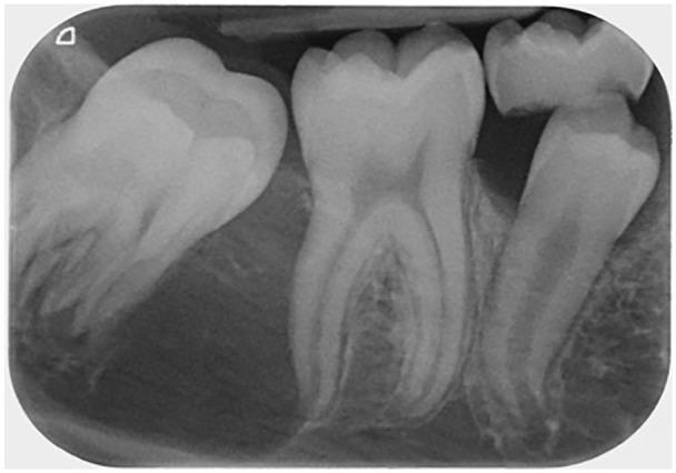
A long-cone periapical radiograph of the mandibular right molar region (LR6/LR7) showing a prominent intraosseous lesion. The image reveals a well-defined, unilocular, and uniformly radiolucent lesion measuring approximately 5 × 10 mm. It is situated between the distal root of the fully erupted permanent first molar and the crown of the unerupted permanent second molar. The lesion extends from the distal cervical area of the first molar toward the apical region of the second molar. The second molar appears mesially tilted and displaced inferiorly by the radiolucency. The adjacent first molar roots show clear morphology without signs of resorption. The cortical borders of the lesion are distinct, suggesting a slow-growing cystic or neoplastic process such as an odontogenic keratocyst (OKC) or dentigerous cyst. This diagnostic image is intended for dental students and clinicians to illustrate the radiographic presentation of unilocular odontogenic lesions and their spatial relationship to developing dentition.
Cone Cut - Definition, Causes, Types, and Correction
As per White and Pharoah's Oral Radiology: Principles and Interpretation
DEFINITION
White & Pharoah: "The x-ray beam may miss part of the receptor, resulting in a partial image (cone cut)."
APPEARANCE ON THE RADIOGRAPH
- A sharply defined, clear (radiolucent/white) area on one edge or corner of the film.
- The clear area has a curved or straight border (corresponding to the edge of the circular or rectangular beam).
- The rest of the image is normally exposed and developed.
- The unexposed area may cut off root apices, alveolar crest, crowns, or interproximal contacts - depending on which direction the beam missed.
WHY DOES IT OCCUR? - CAUSES
PRIMARY CAUSE
Specific Reasons (White & Pharoah):
1. Not Using a Receptor-Holding Device with a Beam-Localizing Ring
- This is the most common and most important cause per White & Pharoah.
- When the patient holds the film with their finger (finger-holding technique), there is no external guide to show where the receptor is positioned inside the mouth.
- The operator has no reference to align the tube head over the film accurately.
- White & Pharoah: "Without an external guide to the position of the receptor, the x-ray beam may miss part of the receptor, resulting in a partial image (cone cut)."
- A receptor-holding device with an external aiming ring (e.g., Rinn XCP) provides a visible ring outside the mouth that the operator aligns the cone with - preventing cone cuts.
2. Poor Alignment of the Tube Head with the Film
- Even when a holder is used, if the operator does not align the aiming cylinder precisely with the external ring, part of the beam misses the film.
- Tube head was not centered over the film - shifted too far mesially, distally, superiorly, or inferiorly.
3. Film/Sensor Displacement or Slipping
- The receptor may slip out of proper position inside the mouth (especially when the patient holds it without a holder).
- The patient may use excessive force, bending or displacing the film from its intended location.
- The film moves but the tube head stays in its set position - they no longer align.
- White & Pharoah: "The receptor might slip, resulting in an improper image field."
4. Use of Rectangular Collimation Without Precise Alignment
- Rectangular collimation produces a smaller beam field that must be precisely aligned with the receptor.
- The smaller the beam, the more critical accurate alignment becomes.
- If the rectangular collimator is even slightly off-center, a cone cut results.
- This is why rectangular collimation must be used with receptor-holding devices - never freehand.
5. Incorrect Horizontal or Vertical Angulation
- Extreme misdirection of the tube head in either horizontal or vertical plane can shift the beam away from the film entirely.
- For example, excessive mesial or distal horizontal angulation with a standard round cone can shift the beam edge off the film margin.
TYPES OF CONE CUT (by Location of Unexposed Area)
| Type | Unexposed Area | Cause |
|---|---|---|
| Mesial cone cut | Mesial (front) portion of film clear | Tube head angled too far distally |
| Distal cone cut | Distal (back) portion of film clear | Tube head angled too far mesially |
| Superior/Cranial cone cut | Top portion of film clear | Tube head aimed too low |
| Inferior/Caudal cone cut | Bottom (apical) portion of film clear | Tube head aimed too high |
CLINICAL SIGNIFICANCE
- Root apices - cannot diagnose periapical pathology
- Alveolar crest - cannot assess bone levels
- Proximal contacts - cannot diagnose interproximal caries
- Crown - cannot assess coronal caries or restorations
CORRECTION / PREVENTION
| Method | How it Prevents Cone Cut |
|---|---|
| Use receptor-holding device with aiming ring (Rinn XCP, DENTSPLY) | Provides external visual guide to align tube head precisely over receptor |
| Align tube head with the aiming ring carefully | Ensures central ray passes through center of film |
| Check film position before exposure | Confirm receptor has not slipped |
| Avoid patient finger-holding | Removes most common cause of misalignment |
| Use round collimation if rectangular alignment is unreliable | Larger beam area is more forgiving (but higher dose) |
White & Pharoah: The use of receptor-holding instruments "facilitates alignment with the x-ray beam, so that the central ray is directed through the contacts in the region being examined" - and prevents cone cuts.
DISTINCTION FROM SIMILAR FAULTS
| Fault | Appearance | Cause |
|---|---|---|
| Cone cut | Sharp-edged clear (white) area on part of film | Beam misalignment - part of film not in beam |
| Underexposure | Entire film pale/light | Insufficient mA, kVp, or time |
| Film not immersed in developer | Clear area at one edge (usually top) | Top of film above developer solution level in tank |
| Overlapping | Proximal surfaces superimposed | Wrong horizontal angulation - beam not through contacts |
Key distinguishing feature of cone cut: The clear area has a sharp, well-defined curved/straight border (the beam edge), and the rest of the film is normally exposed. Underexposure affects the whole film uniformly.