
Give mme detalied information variable-angle body plate in orthopedics
variable angle locking plate orthopedics mechanism biomechanics indications
variable angle locking plate fracture fixation
variable angle locking plate orthopedic fracture fixation
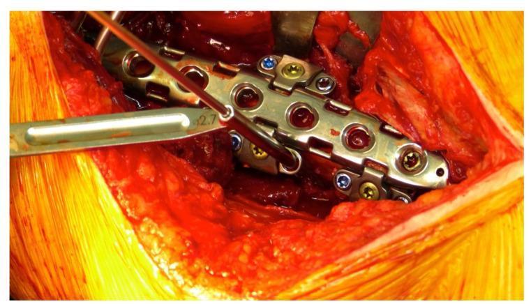
A close-up clinical photograph showing an intraoperative surgical field during orthopedic internal fixation for a periprosthetic fracture. The focal point is a metallic LOQTEQ® Variable Angle (VA) Periprosthetic Plate system secured to a bone. The central locking compression plate (LCP) features multiple circular screw holes. Adherent to the lateral margins of the main plate are specialized attachable hinges designed for variable-angle screw placement. These hinges contain inserted locking screws with color-coded blue and gold heads. A freehand drill guide with a 2.7 mm diameter marking is actively positioned within one of the hinge openings, demonstrating the technique for drilling a pilot hole at a specific angle to bypass existing intramedullary prosthetic hardware. The surgical site displays exposed muscle and soft tissue with moderate hemarthrosis/bleeding typical of open reduction and internal fixation (ORIF) procedures. This image illustrates the application of modular plating systems in complex fracture management where standard monocortical or biaxial screw trajectories are obstructed by an existing implant.
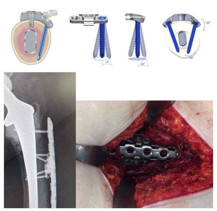
This composite educational graphic illustrates the LOQTEQ VA Periprosthetic Plate system used in orthopedic surgery for periprosthetic fracture fixation. The top row contains technical diagrams demonstrating the hinge-technique for variable angle (VA) screw placement. A cross-sectional anatomical diagram shows the plate fixed to a bone containing a prosthetic stem, highlighting how VA screws bypass the implant. Three schematics detail the 15-degree conical screw angulation and 45-degree rotational hinge capability. The bottom-left image is a clinical radiograph (X-ray) in the lateral view, showing a femoral prosthetic stem with the metallic periprosthetic locking plate and screws positioned to avoid the intramedullary component. The bottom-right image is an intraoperative clinical photograph showing the metallic plate secured to the femur with multiple hinge attachments and screws visible within the surgical field. The system demonstrates a specialized approach for stable internal fixation when a bulky prosthetic implant restricts standard bicortical screw paths.
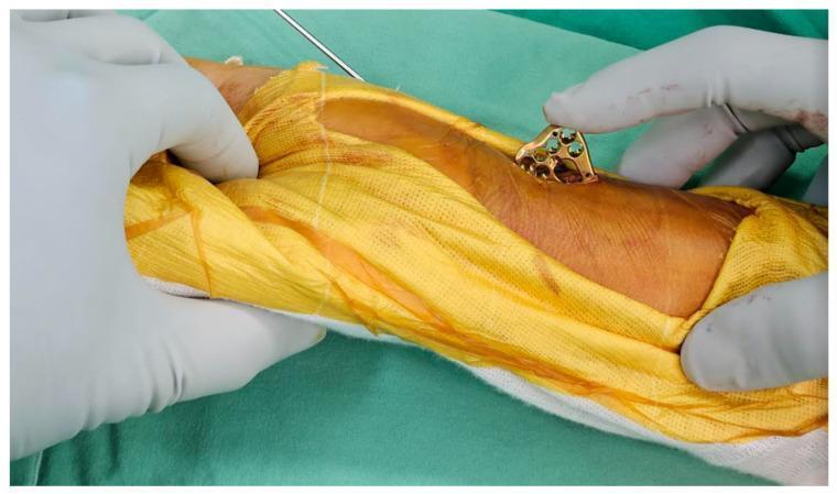
This clinical photograph captures a key step in an orthopedic surgical procedure for distal radius fracture fixation using a mini-incision technique. A surgeon's gloved hand is shown inserting a gold-colored, metallic 2.4 mm variable-angle locking compression plate (LCP) through a small volar incision in the wrist area. The plate features a contoured multi-holed head designed for anatomical fit and is oriented perpendicularly to the skin surface to allow one distal corner to enter the wound first, minimizing soft tissue trauma. The surgical field is prepared with yellow antimicrobial drapes and green surgical cloths, with a thin K-wire partially visible, indicating prior temporary fracture stabilization. This image demonstrates the 'ultimate mini-incision' approach, emphasizing the precise handling and positioning of internal fixation hardware in a restricted surgical window to optimize clinical outcomes and minimize scarring in wrist fracture management.
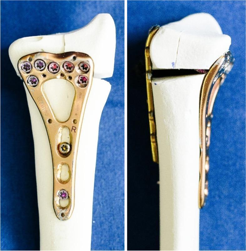
This comparative clinical imaging demonstrates internal fixation techniques for distal radius fractures using synthetic bone specimens. The image is divided into two panels: the left shows a volar locking plate (VLP) construct, and the right shows a double-plating construct. The VLP (left) is a 2.4 mm Variable Angle Locking Compression Plate (LCP) with a two-column design, anatomically contoured to the volar surface of the distal radius. It features multiple locking screws in the head to stabilize articular fragments and shaft screws for cortical fixation. The plate includes 'R' (right) and manufacturer markings. The right panel illustrates a 'sandwich' or double-plating technique, utilizing the same volar plate in conjunction with a supplemental dorsal LCP. This configuration is used to address complex intra-articular fractures with dorsal comminution, particularly involving the lunate facet. The visible osteotomy gap in the specimens simulates a clinical fracture. These constructs highlight orthopedic strategies for achieving rigid stability in distal radius osteosynthesis, emphasizing the difference between standard single-plate volar fixation and dual-plate stabilization for multi-fragmentary fractures.
variable angle locking plate biomechanics clinical outcomes
Variable-Angle Locking Plate (VA-LP) in Orthopedics
1. Definition and Concept
2. Design and Mechanisms of Locking
Fixed-Angle vs. Variable-Angle
| Feature | Fixed-Angle Locking Plate | Variable-Angle Locking Plate |
|---|---|---|
| Screw trajectory | One preset angle only | Up to ±15° off-axis cone |
| Cross-threading risk | High if malangulated | Low - angulation is by design |
| Bending strength | Higher | Slightly reduced |
| Flexibility | Rigid | High |
| Cost | Lower | Higher |
Variable-Angle Locking Mechanisms (by manufacturer design)
- Locking caps - a secondary cap is threaded over the screw head after placement to lock it at the selected angle
- Over-compression screw heads - the screw head deforms slightly to grip the plate at the angle of insertion
- Screws that cut threads into the plate - the locking screw itself machines threads into the plate hole at whatever angle it is inserted
- Tabbed screw holes - flexible tabs in the plate hole deform around the screw head
"The specific design varies by manufacturer, and includes locking caps, over compression screw heads, screws that cut threads into the plate, and tabbed screw holes." - Rockwood & Green's Fractures in Adults, 10th ed., p. 492
3. Biomechanics
How Locking Plates Function
- Axial loads are converted to compressive stress at screw-bone interface (bone is stronger in compression than shear)
- Angular stability leads to uniform stress distribution across all screw-bone interfaces
- All screws must fail simultaneously for the construct to fail (vs. sequential failure in non-locking)
- Particularly beneficial in osteoporotic bone
Variable-Angle Specific Biomechanics
- Bending stability of a 4.5 mm locking plate is reduced to 63% at 5° deviation and 31% at 10° deviation of locking screw insertion vector
- Variable-angle systems provide greatest resistance when the screw is inserted perpendicular to the plate; resistance decreases almost linearly as off-axis angle increases
- Standard (fixed) locking systems provide greater resistance to rotational failure at the screw-plate interface than variable-angle systems
"Care should be taken when using variable angle locking plates because construct stability may be compromised as screw inclination is increased." - Rockwood & Green's, p. 493
"Tidwell et al. found that standard locking systems provided greater resistance to rotational failure at the screw-plate interface than variable-angle locking systems." - Rockwood & Green's, p. 2891
4. Clinical Indications
A. Periarticular Fractures
- Distal femur fractures: VA plates allow screws to be directed into specific articular fragments that would not be accessible at a fixed angle; especially useful in complex comminuted patterns
- Tibial plateau fractures: Screws can be directed toward depressed fragments at custom angles
- Distal radius fractures (volar plating): VA-LCP has a distinct mechanical advantage when fixing a smaller radial styloid fragment - fragment-specific fixation via customized screw placement is possible
- Clavicle fractures: Precontoured plates with VA holes are useful when the plate is not perfectly centered on the clavicle
- Distal humerus fractures: Available in precontoured locking plates for complex articular reconstruction
B. Periprosthetic Fractures
- Standard bicortical screws may be impossible to place (stem obstruction)
- Unicortical locked screws alone have insufficient torsional resistance
- VA locking technology allows surgeons to angle screws around the prosthetic stem to achieve bicortical purchase
- Modular plate systems (e.g., LOQTEQ VA Periprosthetic Plate) use hinged attachments that rotate up to 45° around the plate axis, with ±15° conical angulation
C. Osteoporotic Bone
- When bone quality is poor, the ability to direct screws into the strongest available bone stock (e.g., toward subchondral bone) is valuable
- Bicortical screw purchase is biomechanically superior to unicortical, and VA technology makes it achievable in more circumstances
D. Malreduction or Suboptimal Plate Position
- If the plate cannot be placed in the ideal position (e.g., anatomically precontoured plate slightly off-center), VA holes allow screw trajectories to compensate
5. Common VA-LCP Systems by Anatomical Region
| Region | System Examples |
|---|---|
| Distal femur | Synthes Variable Angle LCP Distal Femur Plate |
| Distal radius | 2.4 mm VA-LCP Volar Distal Radius Plate (Synthes/DePuy) |
| Proximal humerus | VA-LCP Proximal Humerus Plate |
| Periprosthetic femur | LOQTEQ VA Periprosthetic Plate (B. Braun) |
| Clavicle | VA precontoured clavicle plates |
| Tibia | VA-LCP Proximal/Distal Tibia Plates |
6. Surgical Technique Considerations
- Nonlocked screws first: All conventional (nonlocked) screws in the same segment must be placed BEFORE locking screws - mixing sequence improperly can lock a malreduction
- Compression before locking: If compression is desired (stable simple fracture patterns), it must be achieved before locking screws are placed
- Screw angle discipline: Even though VA plates allow angulation, deviating further than the design parameters will reduce construct stability
- Working length: Leave empty holes over the fracture zone (bridges comminution) - the working length determines construct stiffness and micromotion for callus formation
- Plate length: In comminuted/osteoporotic fractures, longer plates with spaced screws provide better stability than short plates with clustered screws
7. Advantages
- Accommodates individual patient anatomy and fracture geometry
- Critical for periprosthetic fractures where a stem obstructs standard trajectories
- Allows fragment-specific screw fixation in complex articular fractures
- Reduces risk of cross-threading (a major problem with fixed-angle locking plates if the surgeon's drill guide drifts)
- Useful when plate positioning is imperfect due to anatomical variation
- Dual functionality: can serve as compression plate or internal fixator/bridging plate depending on technique
- Materials available: stainless steel, titanium alloy, or CFR-PEEK (carbon fiber-reinforced polyether ether ketone)
8. Disadvantages and Limitations
- Lower bending and rotational strength at the screw-plate interface compared to fixed-angle locking plates, especially at high off-axis angles
- Technical complexity: more demanding to use correctly; requires understanding of biomechanical trade-offs
- Higher cost than conventional locking or nonlocking plates
- Clinical evidence remains limited: as stated in Rockwood & Green's, "the clinical effectiveness of variable angle locking technology remains unproven"
- Early mechanical failures have been reported - notably early reports of the Synthes VA locking distal femur plate (J Orthop Trauma, 2016)
- Risk of over-reliance on VA technology to compensate for suboptimal reduction
9. Comparison with Far-Cortical Locking (FCL) Screws
Summary
- Rockwood and Green's Fractures in Adults, 10th ed. (2025), pp. 476, 492-499
- Lenz M et al. "Concept of variable angle locking - evolution and mechanical principles." PMID: 25676391 (2015)
- Zdero R et al. "Biomechanical design optimization of distal femur locked plates." PMID: 37366552 (2023)
give me detailed information on vascularised bone grafts
vascularised bone graft orthopedics types indications technique outcomes
vascularized bone graft free fibula flap reconstruction
give me detailed information on vascularised bone grafts
vascularized bone graft reconstruction outcomes
vascularised bone graft orthopedics types indications technique donor sites complications
vascularised free fibula bone graft reconstruction surgery
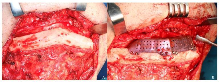
Clinical photograph of an intraoperative maxillofacial reconstruction procedure using a fibula free flap. Figure A shows the surgical exposure of a two-segment fibula flap via a cervical approach. The bone appears pale white with visible surface punctate bleeding, indicating healthy vascularization, and is surrounded by dissected cervical soft tissue and muscle. Figure B demonstrates the placement of a secondary cortico-cancellous iliac crest graft on top of the fibula segments to increase mandibular vertical height. The graft is secured using a custom CAD/CAM titanium mesh, which features a perforated design with 1.5 mm pores to facilitate tissue ingrowth and vascularization. The mesh is fixed to the underlying bone segments with several small diameter (1.5 mm) osteosynthesis screws. This image illustrates complex reconstructive surgery for mandibular defects, specifically addressing vertical discrepancy after primary fibula flap reconstruction.
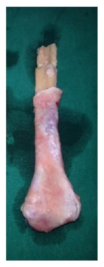
A clinical photograph of an autologous surgical specimen: a prepared free fibular graft intended for proximal ulnar reconstruction. The graft consists of a harvested segment of the upper fibula. The proximal end of the fibular bone shaft is visible as a yellowish-white, rectangular cortical bone segment. The distal portion, representing the fibular head, has been surgically shaped to mimic the anatomical contour of the olecranon process. This head is entirely enveloped in a soft tissue layer, likely consisting of harvested tensor fascia lata, which has been secured to the bone to serve as a biological articular surface. The soft tissue appears pinkish-red and translucent with minimal blood spotting. This composite graft is used in orthopedic oncology or trauma surgery to restore joint function and structural integrity following the excision of bone tumors, such as a giant cell tumor of the proximal ulna.
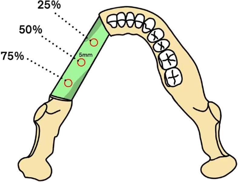
This medical anatomical diagram illustrates a fibula free flap graft integrated into a maxillary or mandibular arch for jaw reconstruction. The diagram shows a green-shaded segment representing the transplanted fibula bone flap positioned between existing segments of the jawbone, which include representations of the teeth and ramus. Three circular Regions of Interest (ROIs), each with a diameter of approximately 5 mm, are indicated along the longitudinal axis of the fibula graft. These ROIs are positioned at three distinct points: 25%, 50%, and 75% of the graft's total length. The illustration demonstrates the standardized methodology for measuring clinical parameters such as Hounsfield Unit (HU) values and Bone Mineral Density (BMD) to assess bone quality, graft integration, and potential resorption during post-operative follow-up. This visualization is intended for maxillofacial surgery and radiology education, highlighting the objective monitoring of reconstructive surgery outcomes.
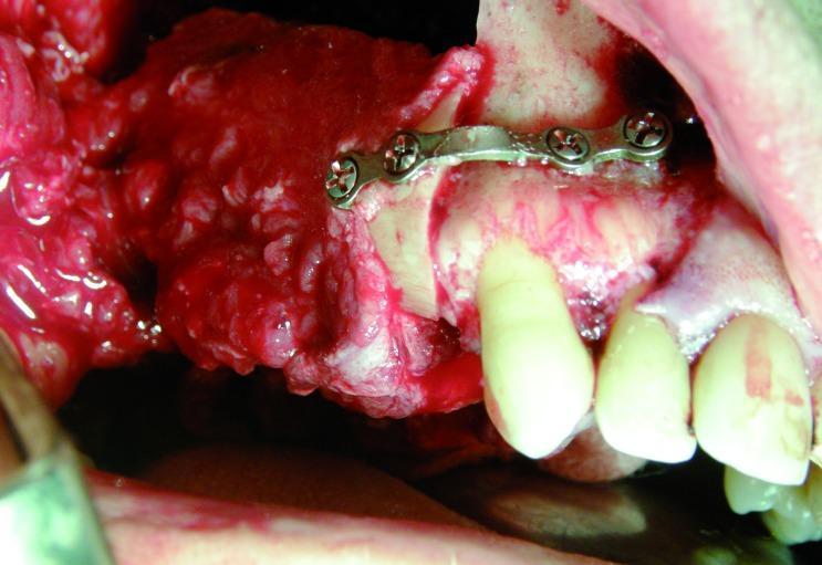
An intraoperative clinical photograph documenting a maxillofacial reconstruction procedure using a vascularized free fibula flap. The image shows the donor fibula segment being integrated into the recipient site (mandible or maxilla). A curved titanium reconstruction mini-plate is prominently visible, spanning the osteotomy site to provide rigid internal fixation between the native bone and the fibula graft. The plate is secured with at least four metallic cortical screws. Adjacent to the surgical site, native teeth are visible, showing proximity to the reconstruction area. The surrounding soft tissues and gingiva appear erythematous and edematous, consistent with acute surgical trauma and perioperative inflammation. This visual illustrates the mechanical fixation and spatial orientation required in microvascular reconstructive surgery for oral cavity defects, often following oncological resection. The focus is on the interface between the hardware, graft, and native anatomical structures.
PMID: 37422827
scaphoid nonunion vascularized bone graft distal radius 1,2 ICSRA avascular necrosis
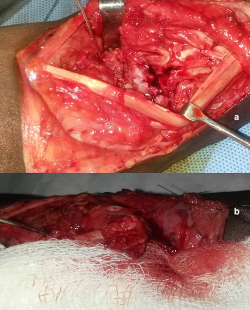
Two-panel clinical photograph displaying intraoperative views of a surgical procedure for scaphoid nonunion with avascular necrosis (AVN). Image (a) shows the dorsoradial wrist incision with the 1,2-intercompartmental supraretinacular artery (1,2-ICSRA) pedicle elevated. A metal retractor exposes the proximal pole of the scaphoid, which appears white and pale, lacking the characteristic 'punctate bleeding' indicative of healthy perfusion, confirming avascular necrosis. Image (b) illustrates the subsequent application of a vascularized bone graft (VBG) harvested from the distal radius. In contrast to the first image, active red punctate bleeding is visible from the graft site, demonstrating successful revascularization and tissue viability. Surgical instruments, including retractors and a needle/suture, are positioned within the field to maintain exposure. The surrounding soft tissues are erythematous and raw, typical of an open surgical field, with white sterile gauze and blue drapes used for fluid management. This clinical sequence highlights a common orthopedic reconstructive technique to treat scaphoid nonunion by providing a biological blood supply to ischemic bone.
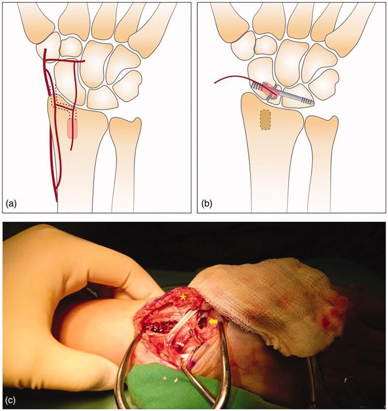
This composite visual represents a surgical technique for treating scaphoid nonunion using a vascularized bone graft (VBG) and scapholunate (SL) screw fixation. Panels (a) and (b) are anatomical diagrams of the dorsal wrist. Panel (a) illustrates the anatomy of the 2,3 intercarpal supraretinacular artery (ICSRA) and the designated donor site on the distal radius for graft harvesting. Panel (b) shows the postoperative schematic where a headless compression screw stabilizes the scapholunate joint, and the vascularized bone graft is inset into the scaphoid. Panel (c) is an intraoperative clinical photograph showing the surgical field through a dorsal approach. An asterisk marks the harvested 2,3 ICSRA pedicled bone graft, still attached to its vascular supply. A yellow arrow points to the recipient cavity prepared in the scaphoid bone at the nonunion site. Self-retaining retractors are used to expose the carpal bones and distal radius. This educational material demonstrates orthopedic microvascular techniques, specifically the use of pedicled grafts for scaphoid reconstruction when vascularity is compromised.
Vascularised Bone Grafts in Orthopedics
1. Definition and Basic Concept
| Property | Non-Vascularised Graft | Vascularised Bone Graft |
|---|---|---|
| Bone cell survival | Graft cells die; replaced via creeping substitution | Osteocytes survive - bone stays alive |
| Incorporation | Slow (months to years) | Faster union possible |
| Large defects (>6-8 cm) | High failure rate | Preferred method |
| Avascular recipient bed | Often fails | Can succeed |
| Irradiated tissue | Poor results | Better results |
| Technical demand | Low | Very high (microsurgery) |
| Operative time | Short | Long |
"Although technically difficult to implant, [vascularised bone graft] allows more rapid union and cell preservation; best for irradiated tissues or large tissue defects." - Miller's Review of Orthopaedics, 9th ed.
2. Biological Basis
- Osteocytes survive - no mass cell death
- The bone can remodel and hypertrophy over time in response to mechanical load
- Osteogenesis, osteoinduction, and osteoconduction are all active
- The graft can bridge avascular zones because it brings its own blood supply
- Even if the vascular anastomosis fails, the graft can still function as a conventional cortical strut (one of the listed advantages)
3. Indications
- Large segmental bone defects - the critical threshold is approximately 6 cm
- Defects up to 6 cm: conventional techniques may suffice
- Defects 6-10 cm: iliac crest or fibula may be appropriate
- Defects >10 cm: free fibula is the graft of choice
- Inadequate soft tissue coverage at the recipient site
- Failed conventional bone grafting - persistent nonunion after standard treatment
- Avascular necrosis (AVN) - femoral head AVN, scaphoid AVN
- Congenital pseudarthrosis of the tibia - notoriously resistant to standard treatment
- Infected nonunion / osteomyelitis - conventional grafts fare poorly in infected beds
- Irradiated bone - post-radiotherapy tissue has severely compromised vascularity
- Bone loss after tumour excision - fibrous dysplasia resection, bone tumour resection
- Scaphoid nonunion with avascular proximal pole
- Composite tissue loss - when both bone and soft tissue need reconstruction (flap with skin island)
- Physeal transfer in children - where longitudinal bone growth is needed
"The transfer of a vascularized bone graft is indicated when traditional bone grafting techniques cannot be done, especially if soft-tissue coverage is inadequate." - Campbell's Operative Orthopaedics, 15th ed. (2026)
4. Donor Sites - The Three Main Sources
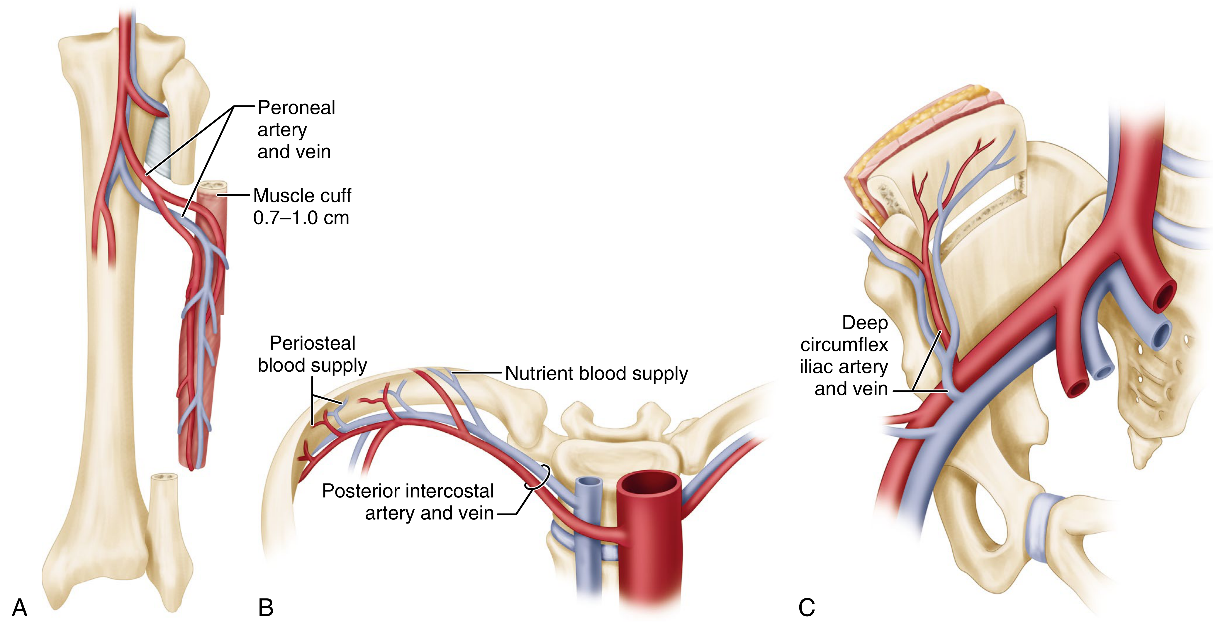
A. Free Fibula (Preferred for Long Bone Defects)
| Feature | Detail |
|---|---|
| Bone type | Straight cortical (tubular) bone |
| Maximum harvest length | ~26 cm in an adult |
| Vascular pedicle | Peroneal artery (1.5-2.5 mm diameter) + 2 venae comitantes (2-3 mm) |
| Pedicle length | 1-5 cm |
| Safe to harvest | Proximal 6 cm and distal 6 cm usually preserved |
| Additional tissue | Muscle cuff (0.7-1.0 cm), proximal articular surface and physis (in children) |
| Skin paddle | Usually unavailable unless a perforator is included |
| Dissection | Lateral approach, superficial and relatively straightforward |
| Best use | Defects >6 cm, long bone reconstruction, mandible |
- Supine position, hip and knee flexed, sandbag under ipsilateral buttock, pneumatic tourniquet applied
- Lateral leg incision centred on fibula, from fibular neck toward ankle
- Develop interval between peroneus longus anteriorly and soleus posteriorly
- Peroneal vessels lie just deep to soleus, nearly in contact with the fibula
- Dissect soleus origin off fibula to expose pedicle; retract peroneal muscles anteriorly in extraperiosteal fashion
- Protect superficial peroneal nerve proximally and flexor hallucis longus posteriorly
- Continue anteriorly, incise anterior intermuscular septum close to fibula
- Harvest required length with osteotomes, maintaining 0.7-1.0 cm muscle cuff around the pedicle
B. Iliac Crest
| Feature | Detail |
|---|---|
| Bone type | Curved corticocancellous bone |
| Harvest length | 8-10 cm usable |
| Vascular pedicle | Deep circumflex iliac artery (DCIA) + vein, or superficial circumflex iliac artery (0.5-3 mm) |
| Pedicle length | 1-5 cm |
| Additional tissue | Skin and cutaneous nerves available as composite flap |
| Best use | Defects 6-10 cm, mandibular reconstruction, femoral head AVN |
C. Rib
| Feature | Detail |
|---|---|
| Bone type | Curved cortical/cancellous |
| Vascular pedicle | Posterior intercostal artery and vein |
| Blood supply | Both periosteal and nutrient (endosteal) |
| Best use | Spinal fusion (as vascular strut), shorter long bone defects |
| Donor complications | Pneumothorax, haemothorax (rare with care) |
D. Medial Femoral Condyle (MFC) - Newer Application
- Blood supply: descending medial genicular artery (branch of popliteal)
- Provides thin but highly osteogenic periosteal tissue
- Useful for: ulna, metacarpals, clavicle, tibia, humerus, mandible, scaphoid
- Can be transferred as a free flap with anastomosis end-to-side to radial artery
E. Distal Radius - Pedicled VBG for Scaphoid
- Donor site: dorsal distal radius
- Vascular pedicle: 1,2-intercompartmental supraretinacular artery (1,2-ICSRA) - a branch of the radial artery
- Indication: Scaphoid nonunion with avascular proximal pole, without humpback deformity
- Technique: Graft harvested as a dorsal pedicled flap and rotated into a prepared trough in the scaphoid
"Bone most commonly harvested from dorsal aspect of distal radius, based on 1,2 intercompartmental supraretinacular artery (1,2-ICSRA). For correction of both humpback deformity and avascular proximal pole: free transfer of medial femoral condyle bone graft, supplied by descending medial genicular, and connected end-to-side to radial artery." - Miller's Review of Orthopaedics, 9th ed.
5. Advantages and Disadvantages
Advantages (Campbell's Box 68.3)
- One-stage procedure - reconstruction is complete in a single operation (vs. Masquelet two-stage technique)
- Tubular bone is mechanically stronger than onlay cortical bone graft
- Transfer of bleeding bone with both endosteal and periosteal circulation to the recipient site
- Can be dowel grafted (intramedullary) into proximal and distal bone ends for stability during anastomosis
- Fallback: can still function as a conventional cortical bone graft if the vascular anastomosis fails
- Hypertrophies with weight-bearing over time - unlike conventional strut allografts which resorb
- Suitable for composite reconstruction (bone + soft tissue + skin + nerve in one flap)
- Functional joints, epiphyses, and skeletal muscle can be included in the composite graft
Disadvantages (Campbell's Box 68.3)
- Long operating time - typically 4-8+ hours; limits use primarily to younger, fit patients
- Elective procedure only - not suitable in emergency or staged settings
- Donor site morbidity - particularly knee and ankle problems after fibula harvest
- Major vessels sacrificed in both donor and recipient limbs
- Difficult assessment of anastomosis patency postoperatively
- Technically demanding - requires microsurgical expertise
- Higher cost and need for specialised facilities
- Risk of vascular thrombosis - if pedicle fails, graft reverts to conventional (slower) incorporation
6. Preoperative Planning
- Preoperative angiography of both donor and recipient limbs - to identify anomalous vascularity, previous vascular injury, or atherosclerotic disease
- For fibula: confirm the leg has three-vessel runoff (anterior tibial, posterior tibial, and peroneal) - peroneal artery can be sacrificed only if the other two are patent
- Select graft source based on defect size and recipient site requirements:
- ≤6 cm: conventional grafting may suffice
- 6-10 cm: iliac crest or fibula
-
10 cm: fibula strongly preferred
7. Specific Clinical Applications
Long Bone Reconstruction (Post-Trauma / Tumour)
- Free fibula is the workhorse
- For tibial defects: the fibula can be intramedullary (dowel technique) or used as an onlay strut
- Over years, the fibula hypertrophies and remodels to resemble the reconstructed bone in cross-section
- Bone healing proceeds from both ends; union typically confirmed on serial radiographs
Congenital Pseudarthrosis of the Tibia
- Highly resistant to conventional grafting
- VBG (free fibula) used after resection of the pseudarthrotic segment
Femoral Head AVN
- Vascularised iliac crest pedicle flap (DCIA-based) used for core decompression + structural support
- Both pedicled iliac crest and free vascularised fibular graft (FVFG) are described
Scaphoid Nonunion with Avascular Proximal Pole
- Pedicled 1,2-ICSRA graft from distal radius: for nonunion without significant humpback deformity
- Free MFC graft: for nonunion with both humpback deformity AND AVN (corrects deformity and restores vascularity)
- Intraoperative punctate bleeding from the proximal pole is the best test of residual vascularity
Oncologic Reconstruction
- After tumour resection, VBG provides a biological alternative to megaprosthesis
- Systematic review (Ebad Ali et al., 2023, PMID: 37422827): VBG shows faster bone union than non-vascularised bone graft after tumour resection (p<0.001), with comparable MSTS functional scores and complication rates
8. Postoperative Monitoring
- Clinical monitoring: temperature, colour, capillary refill of any included skin paddle
- Selective angiography - confirms pedicle flow
- Serial imaging: radiographic monitoring of healing and graft hypertrophy over months
- Bone scintigraphy: can assess graft viability
- Thrombosis of the pedicle is the most feared early complication - results in graft acting as a non-vascularised strut at best, or complete failure at worst
9. Donor Site Complications
| Donor Site | Key Complications |
|---|---|
| Fibula | Ankle instability (5.8%), limited ankle ROM (11.5%), altered sensation (7%), claw toe (6.1%), gait abnormality (3.9%), wound dehiscence (7%), peroneal nerve injury |
| Iliac crest (DCIA) | Lateral cutaneous femoral nerve injury, gait disturbance, incisional hernia, bowel obstruction, hematoma, donor site fracture, pain |
| Rib | Pneumothorax, haemothorax (rare) |
| Distal radius (1,2-ICSRA) | Minimal - small harvest from non-structural site |
| Medial femoral condyle | Typically limited; knee effusion, skin graft donor site issues |
10. Comparison with Alternative Reconstruction Methods
| Method | Advantages | Disadvantages |
|---|---|---|
| VBG (free fibula) | Biological, hypertrophies, durable long-term | Long OR time, donor morbidity, microsurgery needed |
| Masquelet (induced membrane) technique | No microsurgery, reliable for moderate defects | Two-stage, large volumes of graft required |
| Bone transport (Ilizarov) | No donor morbidity | Very long treatment time (1 mm/day), pin complications |
| Megaprosthesis | Immediate function, no graft | Mechanical failure, infection, limited lifespan |
| Allograft strut | No donor site | No vascularity, slow/poor healing, fracture, infection risk |
Summary
- Campbell's Operative Orthopaedics, 15th ed. (2026), Chapter 68 (Free Tissue Transfer)
- Miller's Review of Orthopaedics, 9th ed., pp. 820-835
- Ebad Ali SM et al. "Outcomes Of Reconstruction With Vascularized Vs Non Vascularized Bone Graft After Resection Of Bone Tumours." PMID: 37422827 - Systematic Review & Meta-Analysis, 2023
give me detailed information on vascularised fibular graft
free vascularized fibula graft reconstruction outcomes
free vascularised fibular graft orthopedics technique anatomy indications complications outcomes
free vascularized fibular graft bone reconstruction peroneal artery pedicle
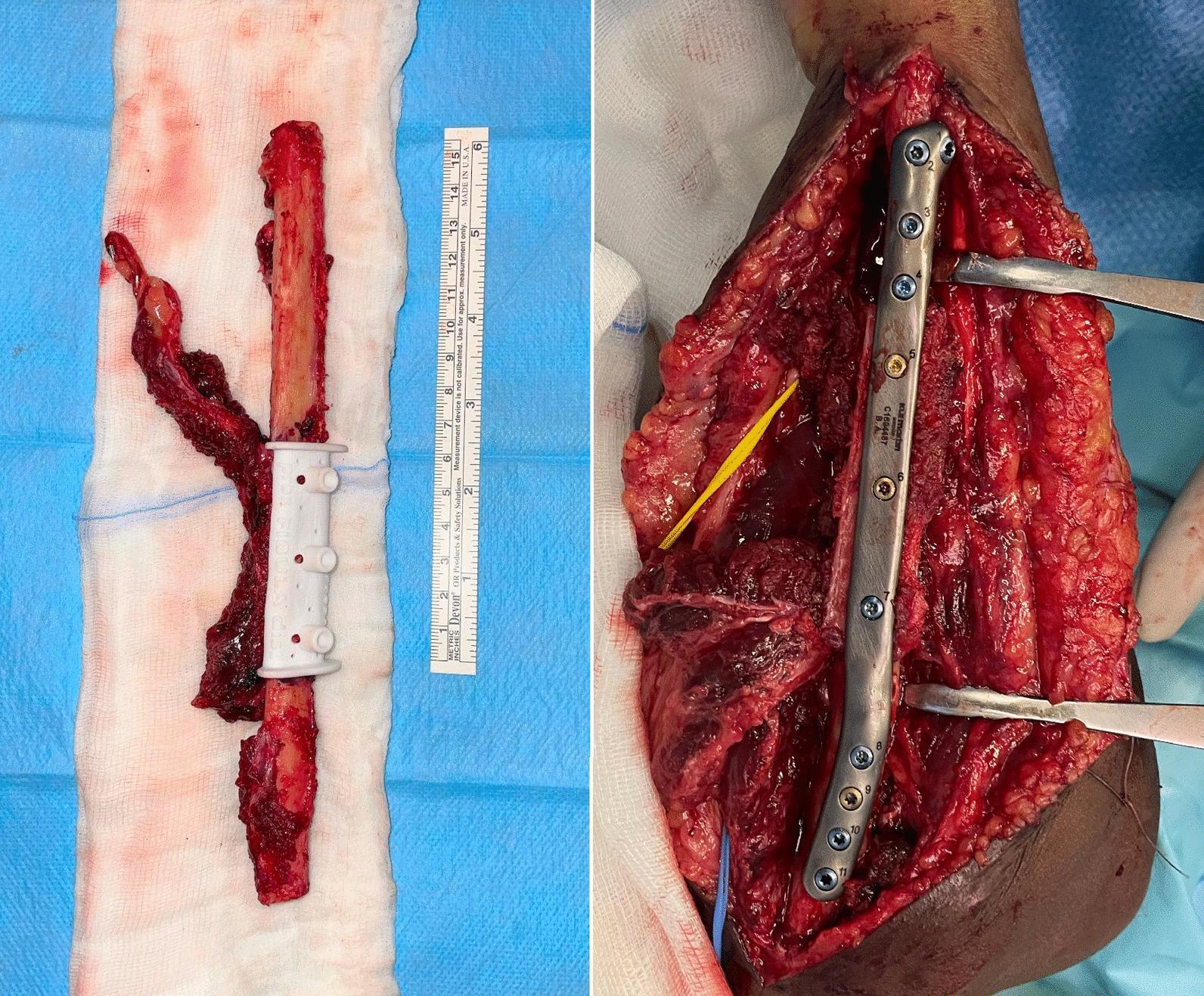
This dual-panel clinical photograph illustrates a microvascular free fibular flap procedure for orthopedic reconstruction. Panel A (left) displays the harvested fibular graft specimen on a sterile drape. It features a vascularized bone segment with an attached vascular pedicle (peroneal artery and venae comitantes) and a white, 3D-printed patient-specific cutting guide fitted centrally to facilitate precise osteotomies. A surgical ruler is positioned alongside for scale. Panel B (right) shows the intraoperative recipient site, likely the forearm, where the fibular flap has been inset to bridge a diaphyseal bone defect. The graft is rigidly stabilized using a long, numbered titanium locking compression plate and multiple screws. Retractors are in place to expose the surgical field, which shows evidence of revascularization and soft tissue integration. This image demonstrates the application of Virtual Surgical Planning (VSP) and custom instrumentation in managing complex nonunions or significant bone loss through vascularized bone grafting.
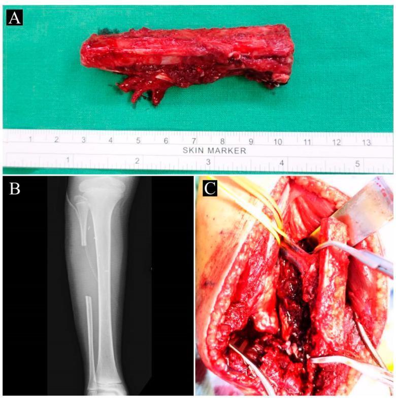
Educational composite image illustrating the harvesting of a contralateral vascularized fibular graft (VFG) for orthopedic reconstruction. Panel A is a clinical photograph of a harvested free fibular graft on a sterile green drape, showing approximately 10 cm of cortical bone with attached vascularized soft tissue and a visible vascular pedicle; a surgical skin marker ruler provides scale. Panel B is a postoperative anteroposterior X-ray of the donor lower leg, demonstrating the residual fibula with a segment missing from the mid-diaphysis, while preserving the proximal and distal ends to maintain knee and ankle stability. Panel C is an intraoperative clinical photograph showing the donor site dissection. It highlights the peroneal artery and accompanying veins identified with yellow vessel loops, and the fibular bone segment being mobilized. This sequence demonstrates the surgical technique for obtaining a vascularized autograft used in treating complex bone defects such as congenital pseudoarthrosis of the tibia (CPT). Relevant specialties include orthopedic surgery, microsurgery, and pediatric orthopedics.
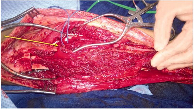
This clinical photograph captures an intra-operative view of a complex tibial reconstruction procedure. The surgical field displays a combination of a fresh-frozen hemi-tibia allograft and a free microvascular fibular graft. The hemi-tibia allograft is positioned deep and fixed to the proximal tibia with surgical plates and screws, providing structural support. Resting atop the allograft is the vascularized fibular graft, which is characterized by its reddish tissue texture. A yellow arrow points to the peroneal vascular pedicle of the fibular graft, showing unconnected vascular structures prepared for microvascular anastomosis. Multiple surgical instruments, including self-retaining retractors and clamps, are visible securing the muscle and soft tissue margins to maintain exposure. This composite grafting technique is typical for managing large segmental bone defects following radical resection of primary bone tumors, such as adamantinoma. The image illustrates the critical spatial relationship between structural allograft support and biological vascularized bone for optimal healing and hypertrophy.
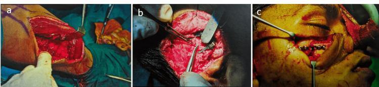
A series of three intraoperative clinical photographs (a, b, and c) documenting the stages of a microvascular free fibular bone graft for midface reconstruction. Image (a) depicts the donor site harvest from the lower leg; surgical retractors expose the fibula and associated soft tissues, where an acrylic template is used to guide osteotomy for graft sizing. Image (b) shows the microsurgical stage at the recipient site in the temporal region, involving the end-to-side anastomosis of the fibular graft pedicle (peroneal artery and vein) to the superficial temporal vessels using fine microsurgical instruments. Image (c) shows the final reconstruction of the right maxilla/midface region. A stainless steel six-hole straight miniplate and fixation screws secure the fibular bone graft into the surgical defect. Key visible landmarks include the patient's closed eye, an elevated facial skin flap, and surgical retractors maintaining the field of view. The clinical sequence illustrates the transition from donor site harvesting to microvascular revascularization and final orthopedic stabilization in craniomaxillofacial surgery.
PMID: 35083566
Vascularised Fibular Graft (VFG) in Orthopedics
1. Introduction and Historical Background
"For most orthopaedic reconstructive procedures, the fibula is the preferred donor bone if its circulation has not been injured." - Campbell's Operative Orthopaedics, 15th ed. (2026)
2. Anatomy of the Fibular Graft
The Fibula as a Donor Bone
| Property | Detail |
|---|---|
| Bone type | Straight, tubular cortical bone |
| Maximum harvestable length | ~26-30 cm in an adult |
| Safe harvest zone | Leave proximal 6 cm (to protect fibular head / common peroneal nerve) and distal 6 cm (ankle stability) |
| Bone diameter | Smaller than most recipient long bones - may require hypertrophy over time |
Vascular Pedicle
- Nutrient (endosteal) artery - the dominant peroneal artery enters the fibula in its proximal third as the nutrient artery - this is why the proximal osteotomy must be within the proximal third
- Periosteal vessels - branches of the peroneal artery supply the outer cortex through a 0.7-1.0 cm muscle cuff
| Vessel | Detail |
|---|---|
| Artery | Peroneal artery, diameter 1.5-2.5 mm |
| Veins | Two venae comitantes (venae comitantes), diameter 2-3 mm |
| Pedicle length | 1-5 cm naturally; can be lengthened by dissecting proximally to the posterior tibial artery origin |
| Origin | Peroneal artery arises from posterior tibial artery |
Composite Flap Options
- Skin paddle (osteocutaneous flap): a skin perforator from the peroneal artery can be included - useful for mandibular reconstruction with soft tissue coverage
- Muscle: a small cuff of surrounding muscle (soleus/FHL) can be included for dead space filling
- Proximal articular surface and physis: in children, the proximal fibular epiphysis can be transferred as a vascularised epiphyseal graft to provide a growing joint surface
3. Indications
Absolute Indications (preferred over conventional methods)
- Large segmental bone defects >6-8 cm - from:
- High-energy trauma with bone loss
- Tumour resection (primary bone tumours, soft tissue tumour resection)
- Osteomyelitis with bone debridement
- Irradiation necrosis
- Defects in a compromised vascular bed - infected, irradiated, or avascular tissue
- Failed conventional bone grafting - persistent nonunion after ≥2 standard attempts
Specific Clinical Scenarios
- Avascular necrosis (AVN) of the femoral head - pre-collapse and early post-collapse stages
- Congenital pseudarthrosis of the tibia (CPT) - a notoriously difficult condition
- Tibial nonunion - especially with segmental defects or previous infection
- Upper limb reconstruction - radius, ulna, humerus defects
- Spine fusion - as a vascular strut in scoliosis or complex spinal reconstruction
- Oncologic reconstruction (in combination with or without allograft - "allograft-prosthetic composite")
- Paediatric bone loss - the physis-bearing graft uniquely allows for skeletal growth
Size-Based Decision Rule (Campbell's)
- Defect ≤6 cm: conventional bone grafting usually sufficient
- Defect 6-10 cm: iliac crest OR fibula
- Defect >10 cm: fibula strongly preferred
4. Preoperative Planning
- Angiography (CT angiography or conventional) of both donor and recipient limbs
- Confirm three-vessel runoff in the leg (anterior tibial, posterior tibial, peroneal) - the peroneal artery can only be sacrificed if the anterior and posterior tibial arteries are intact
- Identify recipient vessels available for anastomosis
- Rule out atherosclerosis or previous vascular injury
- MRI of recipient site - assess bone quality, zone of injury, marrow involvement
- Template planning - calculate defect size; plan osteotomy levels
- 3D printing / Virtual Surgical Planning (VSP) - increasingly used for complex cases (especially mandible) to pre-plan osteotomy angles and graft contouring with patient-specific cutting guides
5. Surgical Technique - Fibular Harvest (Lateral Approach)
Patient Positioning
- Supine, donor extremity with hip and knee flexed, foot slightly internally rotated
- Sandbag under ipsilateral buttock
- Pneumatic tourniquet applied initially to maintain bloodless field
Step-by-Step Technique
Graft Fixation at Recipient Site
- Preferably dowel (intramedullary) technique: each end of the fibula is inserted into the medullary canal of the recipient bone - provides stability during anastomosis and maximises contact area
- Supplemental plates and screws (typically a long locking compression plate)
- Pedicle positioning must be planned before fixation - the pedicle must reach the recipient artery and vein without tension or kinking
- Arterial and venous microsurgical anastomoses are completed after fixation
6. FVFG for Specific Conditions
A. Long Bone Defects (Tibia, Femur, Humerus, Radius/Ulna)
- The fibula is doweled into both proximal and distal medullary canals for stability
- Over months to years, the fibula hypertrophies in response to mechanical loading - the cross-sectional area increases to match the recipient bone's demands
- Serial radiographs confirm progressive union and hypertrophy
- Supplemental conventional cancellous bone grafting at the graft-host junctions may accelerate union
- Union rate: 82% at 2 years, 97% at 5 years
- First union after index procedure: 70% at a mean of 10 months
- Overall union achieved in 91% of patients
- Smoking significantly increases risk of nonunion (p-value significant)
- Locking vs. traditional fixation made no difference to union rates
- Flap survival: 97% (147/151 cases)
- First union rate: 95%
- Second union rate (after revision): 97%
- Overall complication rate: 33%
B. Avascular Necrosis (AVN) of the Femoral Head
- The fibula is introduced through a core decompression track in the femoral neck into the necrotic segment of the femoral head
- The vascular pedicle is anastomosed to the lateral femoral circumflex vessels or terminal branches of the profunda femoris
- The living fibula provides both structural support (preventing femoral head collapse) and biological revascularisation of the necrotic zone
- Best results in Ficat/ARCO stages I-III (pre- and early post-collapse)
- Studies show lower conversion rates to total hip arthroplasty (THA) compared to core decompression alone in young patients (<50 years)
C. Congenital Pseudarthrosis of the Tibia (CPT)
- Vascular supply to a poorly-vascularised pathological tibial segment
- Structural cortical support
- In growing children, the proximal fibular physis can be included to provide continued longitudinal growth
- Important: in children with significant remaining growth, distal tibiofibular fusion (Technique 68.19) is recommended after fibula harvest to prevent progressive valgus ankle deformity - the remaining tibia tends to bow laterally without fibular support
D. Oncologic Reconstruction
- FVFG can be used alone or as a biological component in an allograft-fibula composite (allograft provides immediate bulk and structural support; FVFG provides biological healing at graft-host junctions)
- Can also be combined with megaprosthesis
- The fibula's capacity to hypertrophy makes it superior to inert allografts for long-term durability
7. Postoperative Care
| Phase | Protocol |
|---|---|
| Immediate | Donor leg immobilised briefly for wound healing, prevent equinus contracture |
| Early mobilisation | Gradual weight bearing as tolerated, 3D boot for support |
| Recipient site | Long leg cast (below knee level) with knee flexed, no weight bearing for 3-5 months |
| Monitoring | Bone scan within first week to evaluate graft perfusion |
| Union assessment | Serial radiographs; clinical and radiographic union required before full weight bearing |
| Full weight bearing | When graft shows signs of hypertrophy - may require 15 months or more |
| Supplemental grafting | Conventional cancellous bone grafting may be added at graft-host junctions if needed |
8. Advantages
- One-stage procedure - complete reconstruction in a single operation
- Longest available vascularised bone - up to 26-30 cm, sufficient for even the largest long bone defects
- Tubular cortical bone - mechanically stronger than onlay corticocancellous grafts from iliac crest
- Hypertrophies with loading - the fibula gradually remodels to match the demands of the recipient site
- Reliable pedicle anatomy - the peroneal artery is consistent in location and calibre
- Straightforward dissection - compared to iliac crest, the technique is reproducible
- Composite flap potential - skin paddle, muscle, physis all available
- Fallback safety net - even if the vascular anastomosis fails, the graft still functions as a conventional cortical strut
- Can bridge infected/irradiated beds - brings its own blood supply
9. Disadvantages and Limitations
- Long operative time - typically 4-8+ hours, requiring two surgical teams working simultaneously
- Major vascular sacrifice - the peroneal artery and its comitantes are permanently divided
- Donor site morbidity - ankle and knee problems, wound complications
- Small calibre mismatch - fibula diameter is smaller than most recipient long bones; requires hypertrophy period before full weight bearing
- Technical demand - requires dedicated microsurgical expertise and infrastructure
- Pedicle thrombosis risk - graft failure if anastomosis clots
- Children with growth: risk of progressive ankle valgus deformity if distal tibiofibular fusion not performed
- Assessment of patency is indirect and difficult
10. Donor Site Complications
| Complication | Incidence |
|---|---|
| Transient peroneal nerve palsy | Most common (5 patients in Mayo series) |
| Flexor hallucis longus contracture | Claw toe, reduced ROM (3 patients) |
| Stress fracture of ipsilateral tibia | Rare (1 patient) |
| Compartment syndrome | Rare (1 patient) - risk reduced by leaving fascia open |
| Limited ankle ROM | ~11.5% in systematic reviews |
| Ankle instability | ~5.8% |
| Altered sensation | ~7.0% |
| Persistent donor pain | ~6.5% |
| Gait abnormality | ~3.9% |
| Wound complications (skin grafted sites) | Higher incidence (19.0% vs. 9.9% for primary closure) |
11. Monitoring Graft Viability
| Method | Application |
|---|---|
| Skin paddle monitoring | Temperature, colour, turgor, capillary refill if skin island included |
| Bone scintigraphy | Confirms graft perfusion within first week |
| CT angiography / Doppler | Direct pedicle assessment |
| Intraoperative punctate bleeding | Best intraoperative test of bone viability at graft ends |
| Serial radiographs | Confirm progressive bone union and hypertrophy over months |
12. Comparison with Other Reconstruction Methods
| Method | Best for | Key Limitation |
|---|---|---|
| FVFG | >6 cm defects, AVN, CPT, irradiated beds | Long OR, donor morbidity, microsurgery required |
| Iliac crest VBG | 6-10 cm defects, curved defects | Limited to 8-10 cm; curved shape |
| Masquelet (induced membrane) | Moderate defects with infection | Two-stage; large graft volumes needed |
| Ilizarov bone transport | Any defect length | Very slow (1 mm/day); pin problems |
| Allograft strut | Oncologic bulk replacement | No biology; high fracture/infection rates |
| Megaprosthesis | Immediate function in elderly/oncology | Mechanical failure; limited lifespan |
13. Outcomes Summary
- Union rates approach 97% at 5 years for long bone defects (Houdek et al.)
- Flap survival >97% in upper limb trauma (Liaw et al., PMID 35083566)
- Overall ~90% bony healing in large series
- FVFG delays THA conversion significantly in AVN of femoral head in young patients
- Smoking is the most important modifiable risk factor for nonunion
- Modern locking fixation has not been shown to improve union rates over traditional fixation
- Campbell's Operative Orthopaedics, 15th ed. (2026), Chapter 68 - Techniques 68.18, 68.19
- Miller's Review of Orthopaedics, 9th ed., pp. 820-834
- Liaw F et al. "Outcomes of free vascularised fibular graft reconstruction in upper limb trauma - a systematic review." Eur J Orthop Surg Traumatol. 2023. PMID: 35083566
- Houdek MT et al. "The outcome and complications of vascularised fibular grafts." Bone Joint J. 2017;99-B(1):134-138. Bone & Joint Journal
- Bumbasirevic M et al. "Free vascularised fibular bone grafts in orthopaedics." PMC 4037521 (2014)
give me detailed information on viscosupplementation in orthopedics.
viscosupplementation hyaluronic acid knee osteoarthritis
viscosupplementation orthopedics hyaluronic acid mechanism indications evidence complications 2024
PMID: 41980630
PMID: 37314198
viscosupplementation hyaluronic acid knee injection osteoarthritis
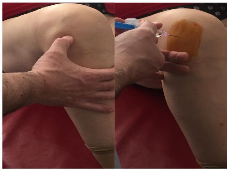
Clinical photograph in a split-frame view demonstrating an intra-articular injection procedure for the knee joint, specifically highlighting an anterolateral portal approach for hyaluronic acid administration in patients with osteoarthritis. The left frame shows the palpation of anatomical landmarks, with the clinician's hand identifying the patellar border and joint line to locate the appropriate entry point. The right frame illustrates the injection phase under aseptic conditions; the skin is prepared with a rectangular patch of povidone-iodine antiseptic solution. An 18-gauge needle attached to a syringe with a blue plunger is seen entering the lateral aspect of the joint space. The knee is positioned in slight flexion, which facilitates access to the joint cavity. This visual serves as an educational guide for orthopedic clinical skills, demonstrating proper site preparation, landmark identification, and needle orientation for viscosupplementation therapy.
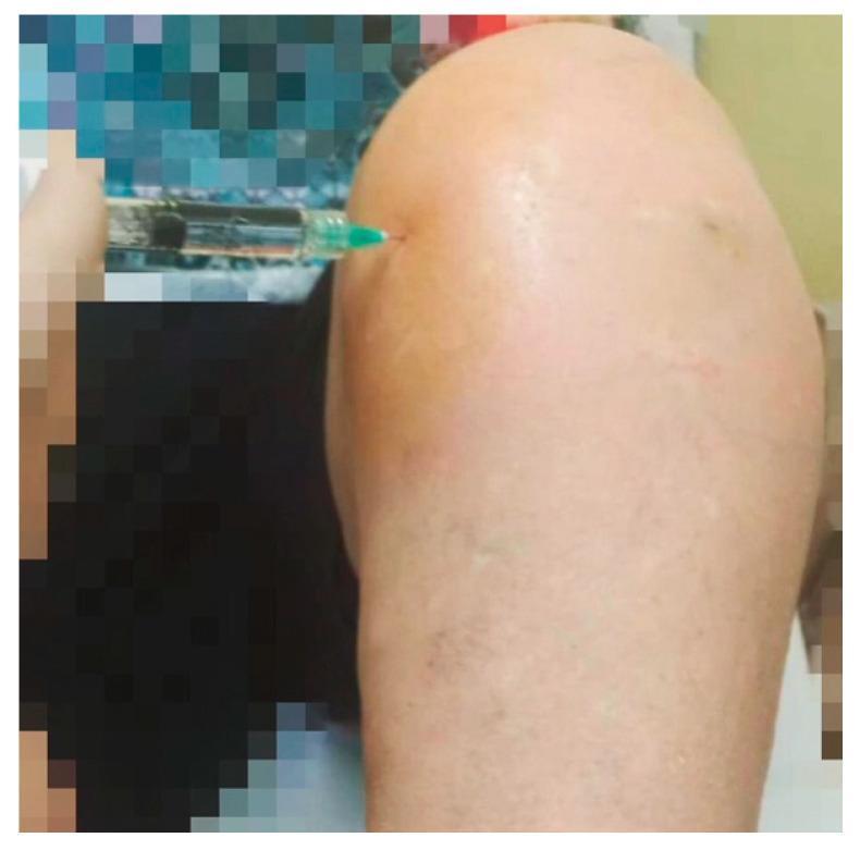
A clinical photograph demonstrating a Medial Infrapatellar (MIP) technique for intra-articular knee injection. The patient's left knee is positioned in approximately 45 degrees of flexion. A 21-gauge needle attached to a clear syringe is seen inserted into the medial aspect of the knee joint. The entry point is located approximately 1 cm inferior and 1 cm medial to the inferior medial margin of the patella. The needle is oriented at an oblique angle, directed toward the retro-patellar space. The surrounding skin shows yellow-brown discoloration consistent with povidone-iodine antiseptic preparation. This image illustrates a common orthopedic procedure for the administration of viscosupplementation, such as hyaluronic acid, or corticosteroids in the management of knee osteoarthritis. The visual focus is on the anatomical landmarks for safe needle placement to ensure intra-articular delivery.
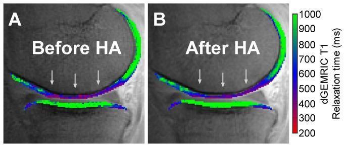
This diagnostic image displays a comparison of delayed Gadolinium-Enhanced Magnetic Resonance Imaging of Cartilage (dGEMRIC) color maps in a sagittal view of the knee joint. The panels illustrate the medial tibiofemoral compartment 'Before HA' (A) and 'After HA' (B), assessing the effect of hyaluronic acid viscosupplementation on cartilage composition. The color overlay represents T1 relaxation times in milliseconds (ms), which serves as a surrogate marker for sulfated glycosaminoglycan (sGAG) content. The color scale ranges from 200 ms (red/purple, indicating low sGAG) to 1000 ms (bright green, indicating high sGAG). In both images, grey arrows highlight a region of the weight-bearing femoral cartilage (wbFC) characterized by blue and red hues, signifying lower T1 relaxation times and depleted sGAG content typical of early-stage osteoarthritis. Conversely, the weight-bearing tibial plateau (wbTP) displays green coloration, suggesting higher sGAG retention. Comparing panels A and B reveals no visually significant change in the T1 relaxation maps following HA injection, indicating that while clinical symptoms might improve, the biochemical composition of the cartilage remains stable.
PMID: 39964439
PMID: 36411508
knee osteoarthritis Kellgren-Lawrence grade X-ray cartilage degeneration
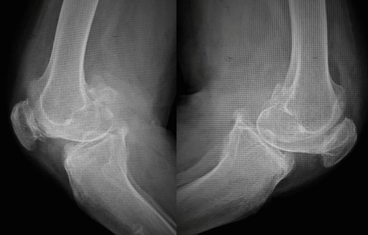
Lateral view X-ray radiography of bilateral knee joints demonstrating advanced degenerative joint disease consistent with Kellgren-Lawrence Grade IV osteoarthritis. The imaging reveals a near-total loss of the tibiofemoral joint space, indicating complete cartilage erosion. Prominent osteophyte formation (bony spurs) is visible on the anterior and posterior aspects of the distal femur and proximal tibia, as well as the superior and inferior poles of the patella. Key radiographic features include significant subchondral sclerosis, characterized by increased bone density at the joint surfaces, and subchondral cyst formation. The alignment shows structural deformity with signs of knee flexion contracture. These findings highlight chronic, severe mechanical degeneration affecting the articular cartilage and underlying bone structure of the femur, tibia, and patellofemoral compartments.
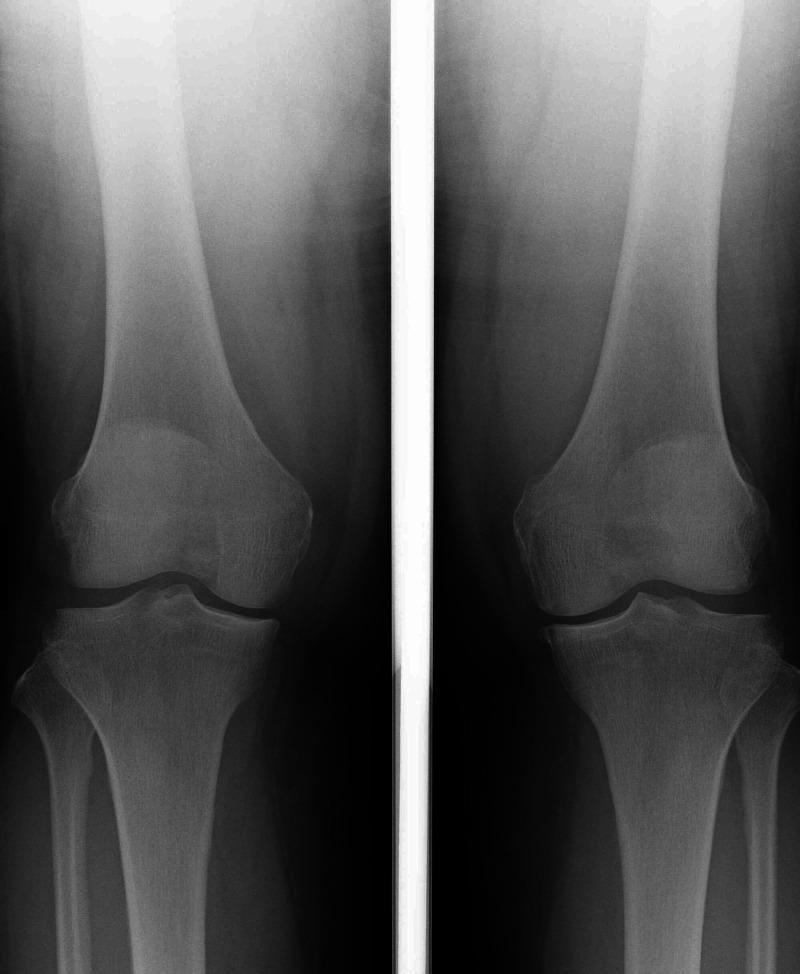
Anteroposterior (AP) weight-bearing X-ray of bilateral knee joints demonstrating degenerative changes associated with osteoarthritis. The imaging shows a bilateral varus alignment, with a measured femorotibial angle (FTA) of 175 degrees in the right knee. Characteristic features of Grade II Kellgren-Lawrence classification are present, including narrowing of the medial compartment joint spaces, marginal osteophyte formation at the femoral and tibial condyles, and mild subchondral sclerosis. These findings are most pronounced in the right knee. The patellofemoral and lateral compartments appear relatively preserved. The visualization of the proximal tibia and distal femur supports an orthopedic evaluation of mechanical axis deviation and joint degeneration. This diagnostic image is intended for clinicians and medical students studying degenerative joint disease and surgical planning for corrective procedures.
Viscosupplementation in Orthopedics
1. Definition and Concept
2. Biology of Hyaluronan in Normal vs OA Joints
Normal Synovial Fluid
- Produced by type B synoviocytes (fibroblast-like cells) and chondrocytes
- A major component of synovial fluid and the extracellular matrix of articular cartilage
- Responsible for the viscoelastic properties of synovial fluid:
- Viscous (resists flow) at slow movements - lubricates
- Elastic (resists deformation) at rapid movements - absorbs shock
- Concentration: 2-4 mg/mL
- Molecular weight: 6-7 million Daltons
In Osteoarthritis
- HA concentration falls to ~1-2 mg/mL
- Molecular weight falls to ~1-3 million Daltons
- The synovial fluid becomes more watery, loses viscoelasticity
- Joint lubrication and shock absorption are impaired
- Chondrocyte function is adversely affected
Mechanisms of Action of Exogenous HA
| Mechanism | Description |
|---|---|
| Mechanical / lubricant | Restores synovial fluid viscosity and elasticity transiently |
| Chondroprotective | Stimulates endogenous HA synthesis by synoviocytes and chondrocytes |
| Anti-inflammatory | Inhibits prostaglandin E2, interleukin-1β, and matrix metalloproteinases (MMPs) |
| Analgesic | Direct effect on nociceptors; reduces bradykinin-mediated pain signalling |
| Scavenges free radicals | HA has antioxidant properties |
| Subchondral bone effects | May reduce osteoclast activation and subchondral remodelling |
| Growth factor stimulation | Promotes chondrocyte proliferation and matrix synthesis |
3. HA Preparations Available
| Property | Low Molecular Weight HA | High Molecular Weight HA |
|---|---|---|
| Molecular weight | 0.5-1.5 million Da | 4-7 million Da |
| Example products | Hyalgan, Supartz (non-crosslinked) | Synvisc (Hylan GF-20), Durolane |
| Injection schedule | Weekly x3-5 injections | 1 injection (if crosslinked) |
| Origin | Avian (rooster comb) or bacterial fermentation | Avian or bacterial |
| Cross-linking | No | Some (e.g. Synvisc) |
4. Indications
Primary Indication
- Knee osteoarthritis - the most evidence-based application; recommended for mild-to-moderate OA (Kellgren-Lawrence grades I-III) in patients who have failed first-line conservative therapies (analgesia, physiotherapy, weight loss)
Accepted Uses in Other Joints
| Joint | Evidence Level |
|---|---|
| Knee (tibiofemoral / patellofemoral) | Most evidence; widely accepted |
| Hip | Growing evidence; ultrasound-guided injection recommended |
| Shoulder (glenohumeral) | Systematic review showing superiority to corticosteroid at longer term |
| Ankle | Emerging evidence |
| Small joints (CMC, MCP, interphalangeal) | Limited/conflicting data |
| Facet joints | Some evidence |
Patient Selection - Who Responds Best
- Earlier-stage OA (KL grade I-III) - grade IV patients (bone-on-bone) respond poorly
- Younger patients with more preserved cartilage
- Patients not responding to NSAIDs/analgesia but not yet surgical candidates
- Patients with contraindications to surgery (comorbidities, anticoagulation)
- Patients wishing to delay arthroplasty
- Patients without significant effusion at the time of injection (effusion predicts poor response and increases risk of acute reaction)
5. Contraindications
| Contraindication | Detail |
|---|---|
| Active joint infection (septic arthritis) | Absolute |
| Known hypersensitivity to HA or avian proteins (for avian-derived products) | Absolute |
| Severe coagulopathy (relative) | Increased haemathrosis risk; generally safe at therapeutic INR |
| Active skin disease or infection at injection site | Absolute |
| Kellgren-Lawrence grade IV (severe/end-stage OA) | Relative - limited benefit |
| Significant joint effusion | Relative - aspirate first, then inject |
6. Injection Technique
Knee Injection Approaches
- Superolateral approach: Needle enters lateral to the superior pole of the patella, directed under the patella. Patient supine, knee extended. Most commonly used.
- Anterolateral approach: Entry at the lateral joint line, 1 cm lateral to the patellar tendon, knee slightly flexed.
- Anteromedial approach: Mirror image of anterolateral, medial infrapatellar point.
- Medial infrapatellar (MIP): 1 cm medial and inferior to the inferior border of the patella, knee at 45° flexion.
- Obesity/difficult anatomy
- Significant osteophytes limit joint access
- Previous failed injections
- Hip, ankle, or small joint injections
- Studies show improved accuracy and potentially better outcomes with US guidance
Step-by-Step Technique (Knee)
- Patient positioned supine, knee extended (or slightly flexed for anterolateral approach)
- Identify landmarks - patellar borders, joint line
- Aseptic skin preparation (povidone-iodine or chlorhexidine)
- Optional: local anaesthetic raised at skin entry point
- If significant effusion present: aspirate first (effusion dilutes HA and reduces efficacy)
- Without changing needle position after aspiration, attach HA syringe and inject
- Needle size: typically 21-22 gauge
- Confirm intra-articular placement by absence of resistance to injection
- Apply gentle pressure after needle withdrawal; ask patient to flex/extend knee to distribute HA
Post-Injection Care
- Avoid strenuous activity for 24-48 hours
- Ice pack if local discomfort
- Short-term rest recommended (though controversial)
- Next injection (if multiple course): 1 week later
7. Injection Schedule
| Product Type | Schedule |
|---|---|
| Low MW HA (Hyalgan, Supartz) | 3-5 weekly injections |
| High MW cross-linked (Synvisc) | 3 weekly injections |
| Single-injection products (Synvisc-One, Durolane, Gel-One) | One injection per course |
| Repeat courses | Supported by evidence; can be repeated every 6 months |
8. Clinical Outcomes and Evidence
What the Evidence Shows
- 2025 Systematic Umbrella Review (Glinkowski & Tomaszewski, J Clin Med): moderate efficacy in pain relief and functional improvement, particularly in early-to-moderate OA
- EUROVISCO Consensus 2024 - 12 international OA experts using Delphi consensus: recommends HA for KL grades I-III who are insufficiently managed with first-line therapies
- LatinVisco Consensus 2026 (PMID: 41980630): 25 experts across Latin America confirmed HA reduces pain, improves function, and has a favourable safety profile in OA grades I-III
- Shoulder OA (Familiari et al. 2023, PMID: 37314198): HA superior to corticosteroids at longer follow-up in glenohumeral OA (effect size 4.43, p=0.00006 for HA+PT vs PT alone)
- Duration of benefit: typically 3-6 months per course; effects often outlast HA residence time in the joint
- Pereira et al. 2022 (BMJ) - 24 RCTs, ~9,000 patients: overall clinically irrelevant pain reduction vs. placebo for knee OA
- Pereira et al. 2024 (Osteoarthritis and Cartilage): HA associated with clinically irrelevant pain reduction and increased harms
- Post-arthroscopic HA injection (Mao et al. 2023, PMID: 36411508): HA after arthroscopic knee surgery showed no significant benefit in pain or function vs. control - not recommended
- HA vs PRP/PRGF (Migliorini et al. 2025, PMID: 39964439): PRGF may be associated with more favourable functional outcomes; no significant difference in WOMAC pain or stiffness
Guideline Positions (Summary)
| Guideline | Recommendation |
|---|---|
| EUROVISCO 2024 | Recommends for KL I-III mild-to-moderate knee OA |
| LatinVisco 2026 | Supports as effective, safe, cost-effective (grades I-III, may consider in IV) |
| OARSI | Uncertain recommendation; may be appropriate for selected patients |
| NICE 2022 (UK) | Do not offer - no evidence of benefit vs. placebo for knee/hip OA |
| RACGP (Australia) 2018 | Conditional/strong recommendation against use |
| AAOS | Inconclusive evidence; unable to recommend for or against |
| ACR 2019 | Conditionally recommends against use for knee OA |
The controversy reflects real biological heterogeneity - patients with early OA and preserved cartilage clearly respond better than those with end-stage disease. Many large negative meta-analyses include end-stage patients who would not be expected to benefit.
9. HA vs Other Intra-Articular Therapies
| Therapy | Onset | Duration | Best for | Key Limitation |
|---|---|---|---|---|
| Hyaluronic acid | Slow (1-4 weeks) | 3-6 months | Mild-moderate OA, younger patients | Conflicting evidence; cost |
| Corticosteroids | Fast (days) | 4-8 weeks | Acute flare, significant synovitis | Repeated use: cartilage toxicity; glucose elevation in diabetics |
| PRP / PRGF | Variable | 4-6+ months | Early OA, younger patients | Higher cost; variable products |
| Stem cells | Slow | Months | Early OA (investigational) | Limited evidence; very high cost |
| Cortisone + HA combined | Fast + sustained | Longer than either alone | Inflammatory component | Theoretical interactions |
10. Adverse Effects and Complications
| Adverse Effect | Incidence | Notes |
|---|---|---|
| Post-injection flare (pseudo-septic reaction) | 0.4-2% | Most common; pain + swelling within 24-72 hours; self-limiting |
| Local pain/soreness at injection site | Common | Transient |
| Local swelling/effusion | Occasional | |
| Septic arthritis | Very rare (<0.001%) | Aseptic technique critical |
| Pseudogout flare | Rare | Crystal deposition disorders |
| Severe acute local reaction (SALR) | ~0.4-2% with some high-MW products | More common with Synvisc/Hylan GF-20; may require aspiration; not true allergy |
| Systemic allergic reaction | Very rare | More risk with avian-derived products |
- Cross-linked (high-MW) products like Synvisc/Hylan GF-20
- Repeated injections (sensitisation)
- Active joint inflammation at time of injection
11. Special Considerations
In Patients on Anticoagulants
- Evidence supports safety of IA injections at therapeutic INR levels (warfarin)
- Also safe with direct oral anticoagulants (DOACs) at therapeutic levels
- Risk of haemarthrosis is small and generally manageable
Repeat Courses
- Supported by systematic review (Altman R et al., Semin Arthritis Rheum, 2018): repeated courses of HA are efficacious and safe
- Typically 1-2 courses per year; minimum 6-month interval between courses
Hip Viscosupplementation
- Must be ultrasound-guided (too deep for accurate blind injection)
- Evidence from 2025 systematic review (PMID: 40343507) supports benefit in hip OA
- Growing acceptance as a bridge to THA
Shoulder Viscosupplementation
- Systematic review 2023: IA HA in glenohumeral OA showed significant improvement vs. baseline and superiority to corticosteroids at longer-term follow-up
- Combined with physiotherapy appears most effective
12. Comparison with the Natural Disease Course
- Reverse cartilage damage
- Cure OA
- Replace surgical treatment in advanced disease
- Reduces pain for 3-6 months per course
- May improve function
- May delay need for surgery in appropriate patients
- Has a favourable safety profile compared to repeated corticosteroids (no cartilage toxicity at normal doses)
13. Summary
- Rheumatology, 2-Volume Set (2022, Elsevier), Chapter references for HA in OA
- Pfenninger and Fowler's Procedures for Primary Care, 3rd ed.
- Hamdan PC et al. "LatinVisco consensus on viscosupplementation for knee OA." Complement Ther Med. 2026. PMID: 41980630
- Familiari F et al. "Efficacy of IA HA injections in glenohumeral OA." J Orthop Res. 2023. PMID: 37314198
- Migliorini F et al. "HA vs PRGF for knee OA: meta-analysis of RCTs." Orthopadie. 2025. PMID: 39964439
- Mao B et al. "HA after arthroscopic knee surgery: systematic review and meta-analysis." Orthop Surg. 2023. PMID: 36411508
give me detailed information on recent advances in wound management
wound management advances dressings biofilm
recent advances wound management 2024 2025 NPWT bioengineered skin substitutes smart dressings growth factors
PMID: 40498297
PMID: 41001070
negative pressure wound therapy VAC dressing chronic wound
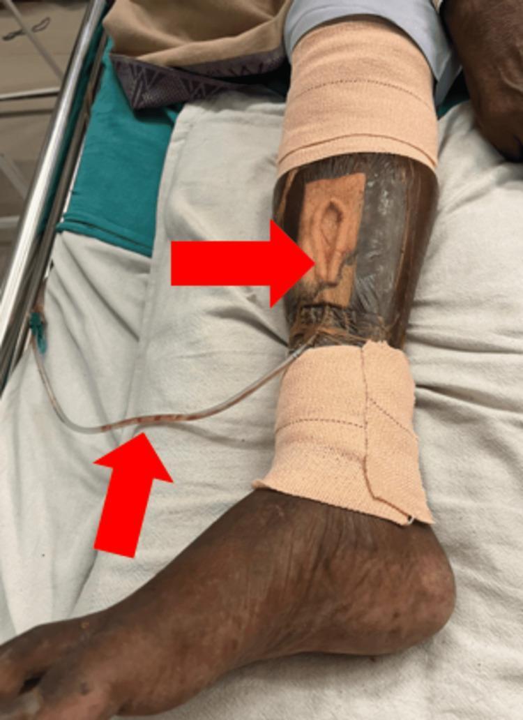
This clinical photograph displays a Vacuum-Assisted Closure (VAC) system applied to a chronic ulcer on the antero-medial aspect of a patient's right lower leg. The visual highlights a multi-component negative pressure wound therapy (NPWT) setup: a porous foam dressing is fitted into the wound bed, sealed under a transparent adhesive drape to maintain an airtight environment. A suction drainage tube, containing serosanguinous fluid, emerges from the inferior aspect of the dressing. The surrounding skin exhibits features consistent with venous insufficiency or chronic stasis, including hyperpigmentation (hemosiderin staining), xerosis, and yellowish discoloration. Compression bandages are applied proximally and distally to the VAC site at the calf and ankle levels. Red arrows indicate the primary wound site under the foam and the drainage tubing. This image serves as a clinical example of advanced wound management for complex lower extremity ulcers, demonstrating the integration of NPWT with standard wound care practices in an elderly patient population.
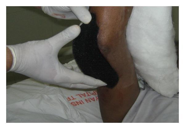
Clinical photograph of a medical professional's gloved hands applying a black, open-cell polyurethane foam dressing to a large wound on a patient's limb, likely the forearm or elbow area. The dressing is a key component of Vacuum-Assisted Closure (VAC) therapy, also known as Negative Pressure Wound Therapy (NPWT). The foam has a distinctive porous, sponge-like texture designed to distribute sub-atmospheric pressure evenly across the wound bed, stimulating granulation tissue formation and removing exudate. The foam appears customized and cut to fit the specific irregular dimensions of the skin lesion. The surrounding skin is of a dark complexion, and a white gauze bandage is visible proximally. This visual demonstrates a critical step in advanced wound care management for complex or chronic wounds, such as grade III open fractures or post-debridement surgical sites, highlighting the application technique and structural properties of hydrophobic open-pore foam interfaces.
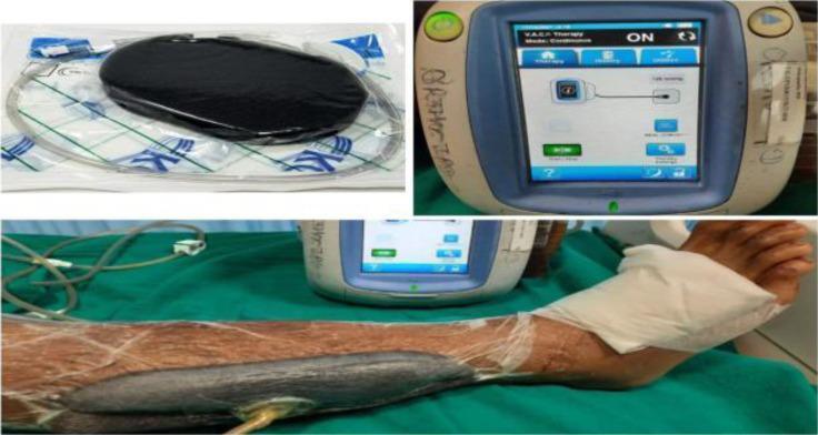
This composite clinical and procedural image illustrates the components and clinical application of a Vacuum-Assisted Closure (VAC) system for negative pressure wound therapy (NPWT). The top-left panel shows the sterile packaging of the premanufactured black polyurethane foam sponge and associated connecting tubing. The top-right panel focuses on the VAC therapy unit's digital interface, displaying an active 'ON' status with a continuous therapy setting of 125 mm Hg, featuring a schematic diagram of the dressing connection. The bottom panel demonstrates the clinical application on a patient's lower leg. A contoured black foam dressing is placed over the wound bed and hermetically sealed with a transparent adhesive drape that extends to the surrounding periwound skin. An evacuation tube is seen emerging from the center of the dressing, connected via a T.R.A.C. pad or similar interface to the vacuum unit. This setup is used in orthopedic and vascular surgery to promote granulation tissue formation, reduce edema, and manage wound exudate in complex or chronic wounds.
PMID: 41339278
bioengineered skin substitute Integra dermal matrix wound healing burn
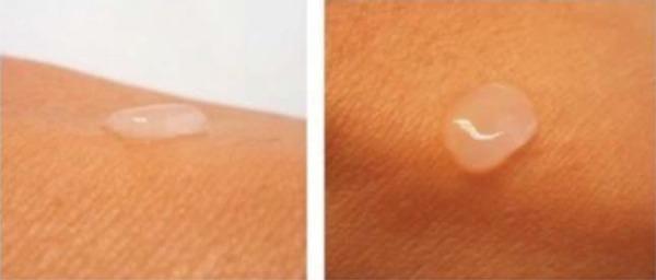
This clinical photograph displays a bioengineered dermal-epidermal skin substitute applied to a patient's skin, shown from both profile (left) and superior (right) perspectives. The substitute appears as a clear, humid, and translucent gel-like droplet that maintains structural integrity and distinct morphology without spreading or dissolving. It exhibits a smooth, reflective surface and adheres well to the underlying tissue. The transparency allows for visualization of the skin's surface texture beneath the graft. This type of scaffold, typically composed of fibrin-agarose and cultured cells like fibroblasts and keratinocytes, is designed for regenerative medicine applications to facilitate wound healing and skin replacement. The image demonstrates the physical properties and clinical handling characteristics of a laboratory-developed dermal substitute in a clinical context.
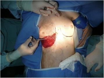
This clinical photograph captures an intraoperative view of a reconstructive surgical procedure on the right breast of a pediatric patient. The image illustrates the application of Integra Bilayer Wound Matrix—a dermal regeneration template—following the release of a post-burn contracture. The Integra material appears as a prominent, reddish-maroon rectangular patch positioned over the lower pole of the breast. It is secured to the surrounding skin margins with absorbable sutures. Surgical markings are visible on the adjacent skin, outlining the planned inframammary fold and surgical approach. A gloved surgeon’s hand is shown using a fine surgical instrument (possibly forceps or a needle driver) to manipulate the material or tissue. The surgical field is framed by sterile blue drapes and gauze. This visual demonstrates a key step in plastic and reconstructive surgery aimed at restoring skin elasticity and allowing for normal breast development in the context of restrictive burn scarring.
Recent Advances in Wound Management
1. Background - The Problem of Chronic Wounds
| Phase | Timeline | Key Events |
|---|---|---|
| Haemostasis | Minutes | Platelet aggregation, fibrin clot, growth factor release |
| Inflammation | Days 1-4 | Neutrophils, macrophages, cytokine release, bacterial clearance |
| Proliferation | Days 4-21 | Fibroblasts, collagen synthesis, angiogenesis, re-epithelialisation |
| Remodelling | Weeks to years | Collagen reorganisation, scar maturation |
2. Wound Bed Preparation - The T.I.M.E. Framework (Updated)
- T - Tissue: Debridement of non-viable, infected, or hyperkeratotic tissue
- I - Infection/Inflammation: Biofilm control; appropriate antimicrobials
- M - Moisture balance: Neither too wet (maceration) nor too dry (desiccation)
- E - Edge of wound: Stimulating epithelial migration; addressing senescent wound edges
3. Advances in Debridement
A. Ultrasound-Assisted Wound Therapy (UAWT)
- Low-frequency ultrasound (20-40 kHz) delivered via mist or direct contact
- Disrupts biofilm mechanically via cavitation
- Stimulates growth factor release and fibroblast activity
- Shown to improve healing in chronic VLUs and DFUs
- Non-contact versions (e.g., MIST Therapy) allow treatment even in fragile tissue
B. Hydrosurgery (Versajet / Aquajet)
- High-pressure water jet system (Bernoulli effect) that selectively removes necrotic tissue while preserving viable tissue
- More precise than conventional surgical debridement
- Single-use disposable system reduces infection risk
- Used particularly in burn wounds and diabetic foot infections
C. Larval Therapy (Maggot Debridement Therapy - MDT)
- Sterile Lucilia sericata larvae applied to wounds
- Mechanisms: enzymatic digestion of necrotic tissue, antimicrobial secretions, growth factor production
- Particularly effective in infected sloughy wounds resistant to conventional debridement
- Systematic reviews confirm superiority to conventional methods for debriding necrotic tissue
- Licensed gel preparations (LarvE, BIOXODERM) allow application without direct larval contact - improving patient acceptance
D. Traditional Surgical Debridement - Updated Evidence
4. Negative Pressure Wound Therapy (NPWT)
Mechanism
- Removes excess exudate and inflammatory mediators
- Reduces oedema - decreases interstitial fluid
- Promotes granulation tissue formation and angiogenesis (macro- and microdeformation of wound edges)
- Decreases bacterial colonisation (debated)
- Draws wound edges together (macrodeformation)
- Increases local blood flow and vascularity
Current Evidence (2023-2025)
- The UK WOLLF trial (prospective RCT for open lower limb fractures): no significant difference in surgical site infections or quality of life between NPWT and standard sterile dressings
- A recent Cochrane review: remains uncertain whether NPWT is superior to standard dressings for wound infection, adverse events, or time to closure
- AAOS 2023 CPG (prevention of surgical site infection after major extremity trauma): NPWT received a strong recommendation in both open and closed fracture situations
"In situations where the wound cannot be closed primarily or there is concern for progression of soft tissue necrosis, negative-pressure wound therapy is recommended." - Sabiston Textbook of Surgery
Modern NPWT Innovations
| Innovation | Description |
|---|---|
| NPWT with instillation (NPWTi) | Adds timed instillation of antiseptic/saline solution (e.g. dakin's, betadine) - improves biofilm disruption; shown to reduce time to OR in complex wounds |
| Single-use portable NPWT (PICO, SVED) | Canister-free, lightweight, silent - enables earlier discharge, outpatient use, improved QoL |
| Abdominal NPWT (AbThera) | Specifically designed for open abdomen/temporary abdominal closure - incorporates a visceral protection layer |
| Endoluminal VAC | Sponge-based endoluminal device for anastomotic leaks (Europe) |
5. Advanced Dressings
A. Antimicrobial Dressings - Beyond Silver
| Dressing Type | Antimicrobial Agent | Mechanism |
|---|---|---|
| Silver dressings | Ag+ ions | Disrupts bacterial cell wall/DNA |
| DACC (Dialkylcarbamoylchloride) | Hydrophobic interaction (e.g. Sorbact) | Physically removes bacteria from wound |
| Iodine dressings (Cadexomer iodine) | Slow-release iodine | Broad-spectrum; disrupts biofilm |
| PHMB (Polyhexamethylene biguanide) | Membrane disruption | Anti-biofilm; low toxicity to human cells |
| Honey (Medihoney) | Low pH, H₂O₂, osmotic effect | Broad-spectrum; anti-biofilm; promotes autolytic debridement |
| Methylene blue/gentian violet foam | Dual-action dye | Anti-biofilm; used in DFUs |
B. Antimicrobial Peptides (AMPs) in Dressings - 2025 Advance
- AMPs are short, cationic peptides (e.g. LL-37, defensins, magainins) with broad-spectrum antimicrobial activity via membrane disruption - fundamentally different from antibiotics
- Low propensity for resistance development - a critical advantage in the antibiotic-resistance era
- Incorporated into: hydrogels, electrospun nanofibre scaffolds, films, sponges, cryogels
- Hybrid systems combine AMPs with:
- Metal nanoparticles (silver, zinc oxide, copper) for synergistic antimicrobial activity
- Stimuli-responsive hydrogels (pH, temperature, glucose-triggered release)
- Exosome carriers for improved delivery
- Additional effects: anti-biofilm activity, immunomodulation, pro-angiogenic, reduced scarring
C. Hydrogel Dressings
- Maintain moist wound environment; donate moisture to dry wounds
- Advanced formulations incorporate growth factors, stem cell-derived exosomes, or antimicrobial agents
- Machine learning-enabled visual monitoring hydrogels (2025): colour-changing dressings that signal infection or healing status to clinicians without removing the dressing
6. Bioengineered Skin Substitutes
Classification (Schwartz's Principles of Surgery)
| Category | Examples | Key Feature |
|---|---|---|
| Autografts | Split-thickness skin graft (STSG), full-thickness skin graft | Gold standard; patient's own cells - no rejection |
| Allografts | Cadaver skin (fresh, frozen, glycerolised) | Best temporary coverage; eventual rejection |
| Xenografts | Pig skin, fish skin (Tilapia), Biobrane, Suprathel | Temporary barrier; some have antimicrobial properties |
| Acellular dermal matrices (ADM) | Integra, BTM, AlloDerm, MatriDerm | Collagen/elastin/GAG scaffold; vascularises and integrates |
| Cellular bioengineered substitutes | Apligraf (bilayer), Dermagraft (fibroblast-seeded) | Living cells; provide growth factors |
| Synthetic biomaterials | Novatek, StrataGraft | Designed de novo; may combine with biologic components |
Key Products in Detail
- Bilayer matrix: inner layer = cross-linked bovine collagen + shark-derived chondroitin-6-sulphate; outer layer = silicone
- The collagen matrix engrafts into the wound over 2-3 weeks as host fibroblasts and blood vessels infiltrate
- Silicone layer is then removed and replaced with thin autograft
- Advantages: closes full-thickness burns, may reduce future scarring, allows autograft harvest from a thinner donor site
- Disadvantages: two-stage procedure; no inherent antimicrobial activity
- Decellularised Atlantic cod or tilapia skin
- Rich in omega-3 fatty acids (anti-inflammatory)
- Promotes granulation tissue; resists bacterial infection
- Studies show comparable or superior outcomes to pig skin in some wound types
- Increasingly used for DFUs and partial-thickness burns
- Living bilayer skin equivalents containing fibroblasts and/or keratinocytes
- Provide continuous delivery of growth factors and cytokines
- FDA-approved for VLUs and DFUs
- Shown to significantly improve healing rates for 12+ week stagnant wounds
7. Cellular and Blood-Product Therapies
A. Platelet-Rich Plasma (PRP) and PRGF
- Autologous blood product concentrated in platelets (4-8x baseline) and growth factors (PDGF, TGF-β, VEGF, EGF)
- Several formulations: PRP, PRGF, PRF (platelet-rich fibrin), PRFM
- Evidence is mixed but growing - FDA-cleared for several wound indications
- Best evidence for: DFUs, chronic ulcers, post-surgical wounds, stimulating granulation in stalled wounds
B. Exosome Therapy (Emerging)
- Exosomes are cell-derived nanovesicles (30-150 nm) containing growth factors, miRNA, and signalling molecules
- Stem cell-derived exosomes (mesenchymal stem cells/adipose tissue) stimulate angiogenesis, fibroblast proliferation, and re-epithelialisation
- No immune reaction (unlike live cell therapy) - a major advantage
- Multiple in vitro and in vivo studies showing promise; early clinical trials under way (2024-2026)
- Incorporated into hydrogel scaffolds for sustained local delivery
C. Stem Cell Therapy
- Mesenchymal stem cells (MSCs) from bone marrow, adipose, or Wharton's jelly
- Promote angiogenesis, modulate inflammation, differentiate into fibroblasts
- Early clinical trials for diabetic wounds show promise
- Cost and regulatory hurdles remain barriers to widespread adoption
8. Wound Microbiome and Biofilm Management
The Biofilm Problem
- >50% of bacterial isolates in DFUs were biofilm producers
- Multidrug resistance exceeded 90% in several cohorts
- Fungi detected in 31% of ulcers by qPCR (but only 9% by culture - highlighting diagnostic gaps)
- Standard care (debridement, antiseptics, NPWT) remains the clinical basis for managing biofilm, but direct antibiofilm clinical evidence is limited
Emerging Antibiofilm Strategies
| Strategy | Mechanism |
|---|---|
| Surfactants (e.g. Prontosan with Betaine) | Disrupt biofilm matrix; reduce surface tension |
| Enzymatic agents | Degrade biofilm matrix proteins and polysaccharides |
| Cold atmospheric plasma (CAP) | Reactive oxygen/nitrogen species disrupt biofilm structure and kill bacteria/fungi |
| Microneedle patches | Penetrate biofilm to deliver antimicrobials directly to bacteria within the matrix (PMID: 40762038) |
| Photodynamic therapy (PDT) | Light-activated photosensitisers generate reactive oxygen species; anti-biofilm and antimicrobial |
| Bacteriophage therapy | Highly specific viruses that lyse target bacteria - particularly valuable for MRSA and MDR Pseudomonas |
| AMP-loaded dressings | (See section 5B above) |
- Accurate wound assessment (NERDS/STONEES criteria for local vs. spreading infection)
- Targeted antimicrobial selection based on culture + sensitivity
- Biofilm-focused strategies
- Antimicrobial stewardship
9. Smart Dressings and Digital Wound Monitoring
Sensor-Embedded "Smart" Dressings
| Sensor Type | Detects | Clinical Value |
|---|---|---|
| pH sensors | Rising pH indicates infection (normal wound pH 6.5-8.9; infected >8.0) | Early infection detection without dressing removal |
| Temperature sensors | Local hyperthermia (≥4°F warmer than contralateral site) | Predicts impending DFU or osteomyelitis |
| Moisture sensors | Exudate level and saturation | Guides dressing change frequency |
| Glucose sensors | Local wound glucose | DFU-specific; correlates with glycaemic control and healing |
| Oxygen sensors | Tissue oxygenation (tcPO₂) | Guides debridement and predicts healing |
| Pressure sensors | Mechanical loading | Detect patient repositioning compliance in pressure injuries |
Electrically Active and Electrostimulation Dressings
- Galvanic microcurrents applied across wound bed
- Mimic the naturally occurring bioelectric signal of intact skin (disrupted by wounding)
- Stimulate fibroblast migration, keratinocyte proliferation, angiogenesis
- PROCELLERA (silver/zinc galvanic wound dressing) is FDA-cleared
Wireless and Telemedicine Integration
- Smart dressings transmit sensor data to smartphones or clinical servers in real time
- Remote wound monitoring platforms (e.g. Tissue Analytics, WoundRounds, Healogics)
- AI-powered wound measurement from smartphone photos - automated wound area, depth, and tissue composition analysis
- Clinical evidence: studies show 11-week faster healing times with bioengineered + monitoring-guided care vs. standard care
10. Growth Factor and Gene Therapy
Topical Growth Factors
| Growth Factor | Product | Application |
|---|---|---|
| PDGF-BB | Becaplermin (Regranex) | DFUs; FDA-approved since 1997 |
| KGF-2 (FGF-10) | Repifermin | Re-epithelialisation (trials) |
| EGF | Heberprot-P (Cuba) | DFUs - available in some countries |
| VEGF | Investigational formulations | Angiogenesis in ischaemic wounds |
Gene Therapy - Emerging Horizon
- Prademagene zamikeracel (Vyjuvek, Krystal Biotech): FDA-approved 2023 - first topical gene therapy for EB wounds, delivering functional COL7A1 gene via HSV vector directly to wound surface
- Proof-of-concept for gene therapy-enhanced wound healing
- Potential future applications: chronic wounds, impaired healing in diabetes, radiation damage
11. Emerging Technologies (2024-2026)
A. 3D Bioprinting of Skin
- Printing layers of keratinocytes, fibroblasts, and extracellular matrix at precise anatomical positions
- In situ bioprinting (printing directly into the wound) is under active development
- Companies like Organovo and Poietis are in early clinical stages
- Custom-geometry grafts: theoretically perfect-fit coverage of irregular wound shapes
B. Oxygen Therapy
- Topical oxygen therapy (TOT): delivers 100% humidified oxygen directly to wound surface via a sealed chamber or film
- Continuous diffusion of oxygen (CDO): electrochemical device generates dissolved oxygen locally
- Evidence for DFUs: accelerated closure vs. standard care in RCTs
- Hyperbaric oxygen therapy (HBO): systemic; supported evidence for DFUs, radiation necrosis, gas gangrene
C. Photobiomodulation (Low-Level Laser Therapy / LLLT)
- Low-energy laser or LED light (typically 630-1000 nm) applied to wound surface
- Stimulates mitochondrial cytochrome C oxidase → increased ATP production → fibroblast and keratinocyte proliferation
- Growing evidence in chronic wounds, diabetic ulcers, and post-surgical wounds
- Non-invasive; increasingly integrated with smart monitoring systems
D. Extracorporeal Shockwave Therapy (ESWT)
- Mechanical pressure waves applied around wound perimeter
- Stimulates angiogenesis (VEGF upregulation), growth factor release, and stem cell recruitment
- Used increasingly in DFUs, pressure injuries, and post-surgical wound complications
12. Wound Management by Wound Type - Summary
| Wound Type | Recent Advance |
|---|---|
| Diabetic foot ulcer | Bioengineered skin substitutes (Apligraf, Dermagraft), NPWT with instillation, offloading technology, antibiofilm strategies, topical oxygen |
| Venous leg ulcer | Compression + advanced dressings; bioengineered substitutes; UAWT |
| Pressure injury | Smart pressure-sensing mattresses; prophylactic silicone dressings; vacuum-assisted closure (stage III/IV) |
| Burn wound | Fish skin xenografts, Suprathel, Integra, spray-on skin (ReCell), portable NPWT for donor sites |
| Open fracture wound | NPWT (strong AAOS 2023 recommendation); early definitive soft tissue coverage (within 7 days); debridement within 24 hours |
| Surgical site infection | NPWTi (with instillation); DACC dressings; antimicrobial sutures |
Summary
- NPWT - portable, instillation-capable devices; strong evidence for open fractures despite mixed results in RCTs
- Advanced debridement - ultrasound, hydrosurgery, larval therapy replacing blunt sharp debridement
- Bioengineered skin substitutes - acellular matrices, living bilayer equivalents, fish skin xenografts
- Biofilm management - antibiofilm dressings (PHMB, DACC, iodine), cold plasma, bacteriophage, AMP-loaded scaffolds
- Smart dressings - pH, temperature, moisture, oxygen sensing with real-time remote monitoring
- Cellular therapies - PRP, exosomes, MSCs providing growth factors and immunomodulation
- Gene therapy - FDA-approved topical gene therapy (Vyjuvek) for EB as a proof-of-concept
- 3D bioprinting, photobiomodulation, ESWT - emerging technologies approaching clinical translation
- Sabiston Textbook of Surgery, Biological Basis of Modern Surgical Practice, Chapters 9 & 10
- Schwartz's Principles of Surgery, 11th ed., Section on Bioengineered Skin Substitutes & Pressure Injuries
- Beraja GE et al. "What's New in Wound Healing: Treatment Advances and Microbial Insights." Am J Clin Dermatol. 2025. PMID: 40498297
- Zhu A et al. "Application of Antimicrobial Peptides in Wound Dressings." Drug Des Devel Ther. 2025. PMID: 41001070
- Theodorakopoulos G, Armstrong DG. "Biofilm in Diabetic Foot Ulcers: A Systematic Narrative Review." Int Wound J. 2025. PMID: 41339278
- Swanson T et al. "IWII Wound Infection in Clinical Practice consensus document: 2022 update." J Wound Care. 2022. PMID: 36475844
Give me detailed information on wrist triple arthrodesis
wrist limited arthrodesis carpal fusion outcomes
wrist triple arthrodesis scapholunate triquetrum technique indications outcomes complications
PMID: 41864627
PMID: 34253392
PMID: 41498712
wrist four corner arthrodesis SLAC SNAC carpal fusion radiograph
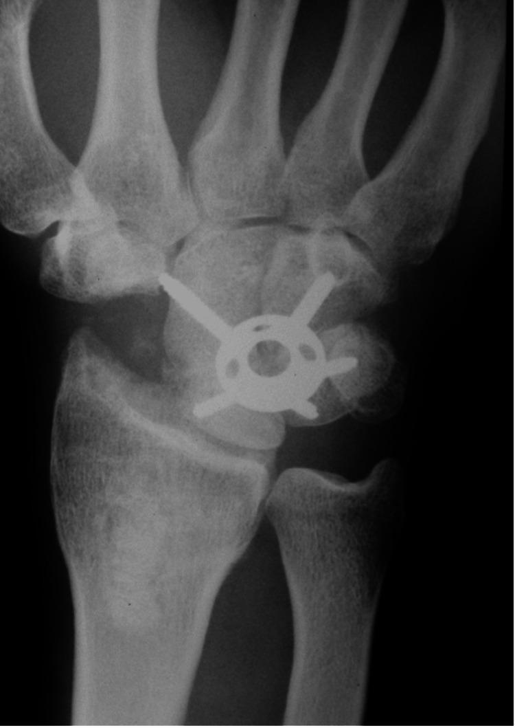
This anteroposterior (AP) x-ray radiograph of the wrist demonstrates a four-corner fusion (4-CF) procedure, a common surgical intervention for advanced carpal collapse conditions such as Scapholunate Advanced Collapse (SLAC) or Scaphoid Non-union Advanced Collapse (SNAC). The image clearly shows the surgical excision of the scaphoid bone, leaving an empty space in the radial aspect of the carpus. Central to the carpal region is a metallic circular plate with radiating screw fixation points. This circular spider plate rigidly secures the lunate, capitate, hamate, and triquetrum bones to promote intercarpal arthrodesis. The radio-lunate joint space appears preserved, which is a functional goal of this procedure. Radiographic features of fusion include the hardware's position spanning the four bones and the loss of discrete joint lines between the involved carpals. This visual is highly relevant for orthopaedic surgery and radiology education, illustrating the hardware configuration and anatomical changes following limited wrist arthrodesis.
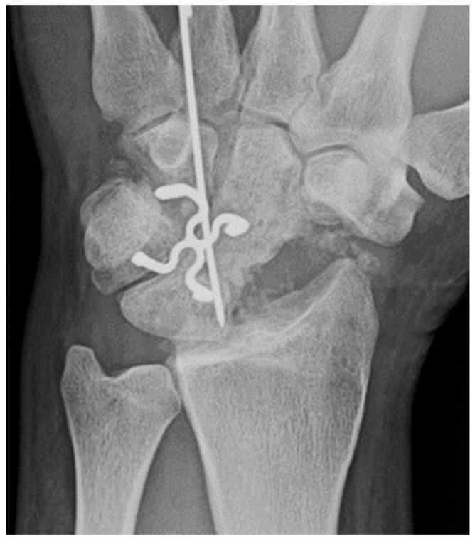
This posteroanterior (PA) X-ray of the wrist demonstrates a four-corner fusion (arthrodesis), a surgical procedure typically used to treat advanced carpal collapse or arthritis (e.g., SNAC or SLAC wrist). The scaphoid bone is absent, consistent with a total scaphoidectomy. The remaining four carpal bones—the lunate, capitate, hamate, and triquetrum—are consolidated into a single unit. Surgical hardware is central to the image, featuring multi-pronged zig-zag shaped surgical staples that traverse the intercarpal joints to promote bony fusion through compression. Additionally, a vertical Kirschner wire (K-wire) is visible, providing temporary longitudinal stabilization and alignment through the capitate and lunate toward the distal radius. The distal radius and ulna are intact, showing clear joint spaces at the radiocarpal interface despite the midcarpal fusion. This visual serves as a primary example of limb-salvage orthopaedic surgery aimed at preserving limited wrist motion while alleviating pain from degenerative carpal instability.
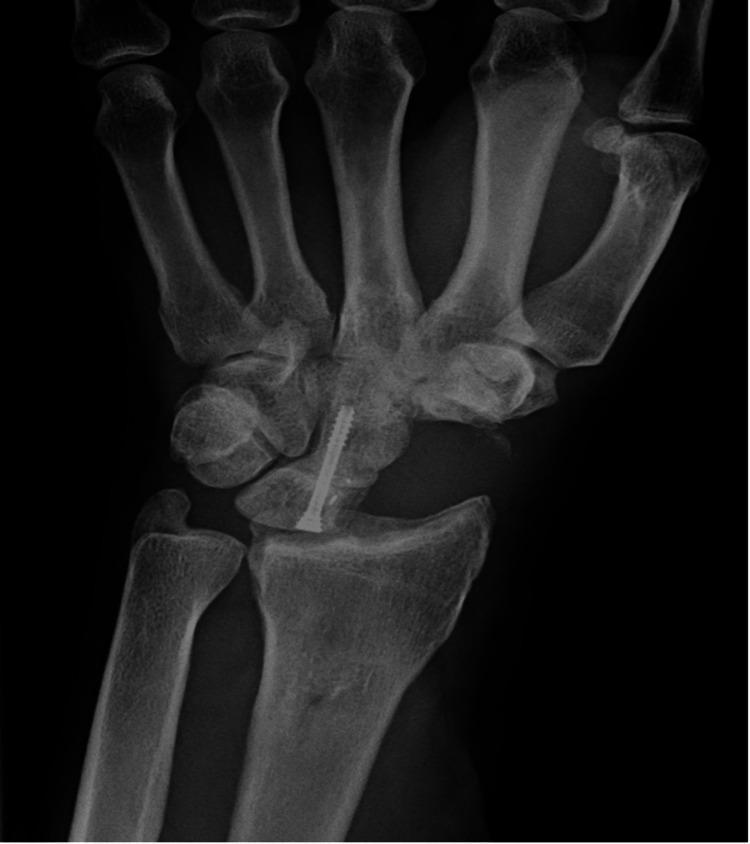
This anteroposterior (AP) radiograph of the wrist demonstrates a status post-surgical intervention for advanced carpal collapse, specifically a capitolunate arthrodesis (fusion). A single orthopedic headless compression screw is visible, traversing longitudinally from the lunate into the capitate to facilitate stable fusion. There is a notable absence of the scaphoid bone, consistent with a total scaphoid excision. The distal radius is seen articulating directly with the lunate. The surrounding carpal architecture shows the triquetrum and hamate in situ, though the normal proximal carpal row alignment is altered due to the excision and fusion. This procedure is typically indicated for treating advanced Scapholunate Advanced Collapse (SLAC) or Scaphoid Nonunion Advanced Collapse (SNAC) to preserve wrist motion while addressing degenerative arthritis.
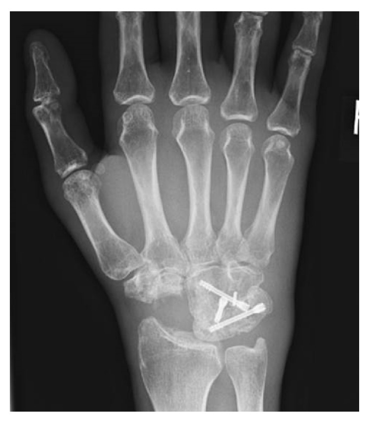
**Imaging Modality:** Conventional Radiography (X-ray) **Anatomical Region:** Right hand and wrist **View:** Anteroposterior (AP) projection **Observed Pathology/Findings:** The image demonstrates a status post-surgical intervention for carpal collapse, specifically a four-corner arthrodesis. The scaphoid bone is absent, consistent with a total scaphoidectomy. Internal fixation is visible within the midcarpal joint, consisting of three headless compression screws (e.g., Herbert screws) securing the capitate, hamate, triquetrum, and lunate. **Characteristic Visual Features:** * **Fusion:** There is radiologic evidence of consolidated osseous bridging across the capitate-lunate, capitate-hamate, hamate-triquetrum, and lunate-triquetrum interfaces, indicating a successful fusion mass. * **Alignment:** The radiolunate joint space is preserved. * **Hardware:** The metallic screws are intact with no evidence of loosening, migration, or periprosthetic lucency. * **Secondary Findings:** Mild degenerative changes are noted at the first carpometacarpal (CMC) joint and distal radioulnar joint. **Key Diagnostic Features:** Post-scaphoidectomy four-corner fusion with stable internal hardware and mature bony union, typically performed for SLAC (Scapholunate Advanced Collapse) or SNAC (Scaphoid Nonunion Advanced Collapse) wrist patterns.
SLAC wrist scapholunate advanced collapse radiograph stages radioscaphoid arthritis
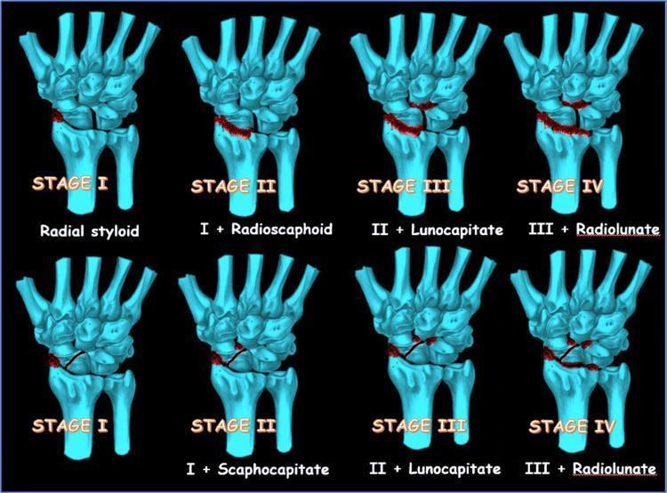
An anatomical diagram and comparison chart illustrating the progressive stages of Scapholunate Advanced Collapse (SLAC) and Scaphoid Nonunion Advanced Collapse (SNAC). The visual uses light blue 3D skeletal models of the wrist and hand against a black background, with red highlights indicating areas of arthritic degeneration and joint space narrowing. The top row depicts the four stages of SLAC: Stage I involves the radial styloid; Stage II extends to the radioscaphoid joint; Stage III adds lunocapitate joint involvement; and Stage IV includes pancarpal arthritis affecting the radiolunate joint. The bottom row depicts the four stages of SNAC: Stage I involves the radial styloid; Stage II progresses to the scaphocapitate joint; Stage III involves the lunocapitate joint; and Stage IV results in radiolunate joint involvement. This educational resource demonstrates the predictable pattern of carpal instability and subsequent secondary osteoarthritis in the wrist, highlighting the preservation of the radiolunate joint until the final stage in both conditions.
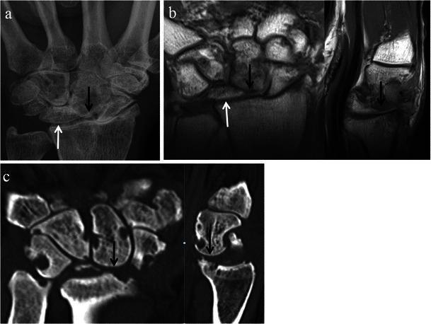
This composite of diagnostic images illustrates the late stages of Scapholunate Advanced Collapse (SLAC) wrist. Panel (a) is a posteroanterior (PA) radiograph showing marked carpal instability and degeneration. Panel (b) features coronal and sagittal T1-weighted MRI views, and panel (c) shows coronal and sagittal CT reformats. The primary diagnostic features highlighted across all modalities include significant proximal migration of the capitate (indicated by black arrows) and ulnar displacement of the lunate (white arrows). These structural shifts indicate a loss of carpal height and severe disruption of the normal ligamentous support. Extensive osteoarthritic changes are evident, characterized by joint space narrowing, subchondral sclerosis, and osteophyte formation, particularly at the radioscaphoid and capitolunate articulations. This advanced pattern of arthropathy typically follows chronic scapholunate ligament dissociation, leading to the characteristic 'collapse' of the carpus and progressive joint destruction.
Wrist Triple Arthrodesis (Three-Corner Fusion)
1. Clarifying the Terminology
- Three-Corner Fusion (3CF) - also called "capitolunate arthrodesis" with scaphoid and triquetrum excision: fuses only the capitate and lunate after excising both the scaphoid and triquetrum; effectively a two-bone fusion within the former four-corner complex
- Scaphotrapeziotrapezoid (STT) arthrodesis (triscaphe fusion) - fuses scaphoid, trapezium, and trapezoid
- Radioscapholunate (RSL) arthrodesis - fuses the radius, scaphoid, and lunate (a radiocarpal partial fusion)
2. Wrist Anatomy and Biomechanics Relevant to Arthrodesis
- Radiocarpal joint: distal radius articulates with the proximal carpal row (scaphoid, lunate, triquetrum)
- Midcarpal joint: proximal row articulates with the distal row (trapezium, trapezoid, capitate, hamate)
- Intercarpal joints: between individual carpal bones
Normal Carpal Kinematics
- Wrist flexion/extension: approximately 50% occurs at the radiocarpal joint, 50% at the midcarpal joint
- Radial/ulnar deviation: predominantly midcarpal
- The scaphoid acts as a mechanical link between proximal and distal carpal rows, transmitting forces from the distal row to the radius
3. Pathological Background - SLAC and SNAC Wrist
SLAC Wrist Staging (Watson and Ballet, 1984)
| Stage | Location of Arthritis |
|---|---|
| Stage I | Radial styloid-scaphoid |
| Stage II | Entire radioscaphoid joint (scaphoid fossa of radius) |
| Stage III | Capitolunate joint (midcarpal) |
| Stage IV | Radiolunate joint (pancarpal) - rare |
SNAC Wrist Staging
| Stage | Location of Arthritis |
|---|---|
| Stage I | Radial styloid |
| Stage II | Radioscaphoid joint |
| Stage III | Scaphocapitate joint |
| Stage IV | Radiolunate joint |
4. The Spectrum of Limited Wrist Arthrodesis
| Procedure | Bones Fused | Bones Excised | Best For |
|---|---|---|---|
| STT (Triscaphe) fusion | Scaphoid + Trapezium + Trapezoid | None | DISI, SL instability without arthritis |
| Scapholunate (SL) arthrodesis | Scaphoid + Lunate | None | SL dissociation (pre-arthritic) |
| Four-corner fusion (4CF) | Capitate + Hamate + Lunate + Triquetrum | Scaphoid only | SLAC/SNAC stages II-III |
| Three-corner fusion (3CF) | Capitate + Lunate | Scaphoid + Triquetrum | SLAC/SNAC stages II-III (alternative to 4CF) |
| Radioscapholunate (RSL) fusion | Radius + Scaphoid + Lunate | Often distal scaphoid ± triquetrum | Radiocarpal arthritis (RA, post-traumatic) |
| Total wrist arthrodesis | All carpal joints + radiocarpal | None | End-stage (stage IV) or failed partial fusion |
| Proximal Row Carpectomy (PRC) | N/A (excision, not fusion) | Scaphoid + Lunate + Triquetrum | SLAC/SNAC II-III, older/lower demand patients |
5. Four-Corner Arthrodesis (4CF) - The Gold Standard
Concept
Indications
- SLAC wrist stages II and III
- SNAC wrist stages II and III
- Failed proximal row carpectomy (in some cases)
- Younger, high-demand patients (preferred over PRC for grip strength)
Contraindications
- Radiolunate arthritis (Stage IV SLAC/SNAC) - indicates total wrist arthrodesis
- Active infection
- Inadequate bone stock
- Open distal radial physis (relative)
6. Three-Corner Arthrodesis (3CF) - The "Triple" Fusion
Concept
- Three-corner arthrodesis
- Capitolunate arthrodesis (with scaphoid and triquetrum excision)
- Bicolumn fusion (less common)
- "Triple fusion" when described as fusing across three remaining carpal bones
Rationale for Triquetrum Excision
- Easier lunate reduction (the triquetrum often tethers the lunate in a VISI position)
- Reduces fusion surface complexity - only two bones to fuse (capitate-lunate)
- Avoids subsequent pisotriquetral arthritis (a known complication of 4CF)
- Some studies show comparable or superior outcomes to 4CF
Indications
- SLAC/SNAC stages II-III (same as 4CF)
- Cases where pisotriquetral arthritis is pre-existing or anticipated
- Surgeon preference when lunate reduction is difficult in 4CF
7. Surgical Technique - 4CF/3CF
Patient Positioning
- Supine, arm on hand table, tourniquet at arm
- Image intensifier (C-arm) available throughout
Approach (Dorsal)
- Incision: Longitudinal dorsal incision centred on the third metacarpal axis. Longitudinal preferred (allows future conversion to total wrist arthrodesis if needed)
- Retinaculum: Incise extensor retinaculum in Z-fashion; preserve or transpose extensor pollicis longus (EPL) radially
- Capsule: Longitudinal capsulotomy - two incisions (between ECU/EDC, and between EDC/ECRL intervals) or single "ligament-sparing" approach preserving dorsal radiocarpal ligaments
- Expose carpus: Identify all carpal bones and assess joint surfaces
Scaphoid Excision
- Remove scaphoid piecemeal using osteotomes, rongeur, or burr
- Preserve radioscaphocapitate (volar) ligament to prevent carpal instability
- Preserve at least the proximal fibres to avoid ulnar translation of the carpus
Triquetrum Excision (for 3CF)
- Remove triquetrum similarly; preserve pisiform (sesamoid in FCU)
- Facilitates lunate reduction into neutral position
Cartilage Removal / Joint Preparation
- Denude all articular cartilage from the planned fusion surfaces using rongeur, curette, or motorised burr
- Create a flat, bleeding cancellous bone surface on each side
- Decortication extends to subchondral bone
Reduction and Alignment
- Critical step: Reduce the lunate into neutral (neither DISI nor VISI)
- The capitate-lunate axis must align with the longitudinal axis of the radius
- Use fluoroscopy to confirm normal carpal height and alignment
- Provisional K-wire fixation to hold reduction
Bone Grafting
- Cancellous bone graft from the excised scaphoid (± triquetrum) is packed into all fusion gaps
- Additional iliac crest, distal radius, or cancellous allograft if insufficient
Fixation Methods
| Method | Details | Notes |
|---|---|---|
| K-wires | Simple; most historical data | Remove at 6-8 weeks; higher revision rate |
| Headless compression screws | 2-4 screws across capitate-hamate-lunate-triquetrum | Good compression; minimally invasive |
| Staples | Compression staples across joints | Fast; less precise |
| Circular spider plate (e.g. Acutrak, Biomet) | Circular plate with 4 peripheral prongs into each bone | Most rigid; single dorsal plate; most popular currently |
| Locking dorsal plate | Radiolucent or metal | Good construct; plate-related complications described |
- All fixation methods produce similar radiographic union rates - no significant difference between K-wire, screw, staple, non-locking plate, metal locking plate, and radiolucent locking plate
- Grip strength was significantly lower with metal locking plates (63.2%) vs K-wires (82.6%)
- No clinically relevant differences in range of motion between groups
- Conclusion: fixation method choice should be guided by surgeon experience and anatomical factors, not expected fusion rates
Closure
- Repair dorsal capsule
- Repair extensor retinaculum
- Skin closure; drain optional
- Volar or dorsal splint applied in neutral position
8. Arthroscopic Approach - Recent Advance
- Arthroscopic 4CF and 3CF are now established techniques
- Advantages over open: potentially reduced soft tissue trauma, less postoperative pain, faster rehabilitation, smaller scars
- Arthroscopic approaches may preserve more motion and grip strength in early follow-up
- Limitations: technically demanding; longer operative time; fluoroscopy-dependent; limited long-term comparative data vs. open
- Both compression screws and circular plates can be inserted arthroscopically or mini-open
9. STT (Scaphotrapeziotrapezoid) Arthrodesis
Concept
Indications
- Scapholunate dissociation (pre-arthritic, to stabilise the scaphoid)
- STT osteoarthritis (occurs in ~40% of wrist radiographs in the elderly)
- Rotatory subluxation of the scaphoid
- Kienbock disease (stage II-IIIa)
Biomechanical effect
- Stabilises the scaphoid in a slightly extended position relative to the lunate
- Reduces the SL gap
- Preserves more radiocarpal motion compared to 4CF (because the radiocarpal joint is untouched)
Limitations
- High nonunion rate in early series (corrected with modern fixation)
- Risk of radioscaphoid impingement if scaphoid is over-corrected
- Does not address established radioscaphoid arthritis
10. Radioscapholunate (RSL) Arthrodesis
Concept
Indications
- Radiocarpal arthritis (rheumatoid arthritis, post-traumatic)
- Distal radius malunion with radiocarpal arthritis
- Kienbock disease stage IV
- SLAC/SNAC with specific radiocarpal involvement
Key technical detail
- Distal scaphoid excision (DSE) with RSL fusion: improved postoperative wrist flexion (+8°) and radial deviation (+3°), reduced nonunion rates, and reduced secondary midcarpal OA
- Combined DSE + triquetrum excision (TE): best motion gains BUT highest rate of secondary midcarpal OA - likely due to increased laxity allowing abnormal loading
- Recommendation: DSE is beneficial; triquetrum excision requires careful selection
11. PRC vs 4CF/3CF - Comparative Decision Making
| Feature | Proximal Row Carpectomy (PRC) | Four/Three-Corner Fusion |
|---|---|---|
| Bones removed | Scaphoid + Lunate + Triquetrum | Scaphoid only (4CF) or S + T (3CF) |
| New articulation | Capitate head on lunate fossa of radius | Fused carpal mass on radiolunate joint |
| Range of motion | More (60-70% of normal) | Less (50-60%) |
| Grip strength | Lower (54% contralateral) | Better (65%) |
| Complications | Fewer | More hardware-related |
| DASH score | Higher (worse) - 32 vs 19 | Lower (better) - 19 |
| Patient-rated wrist score | Similar (27 PRC vs 28 4CF) | Similar |
| Prereq: capitate articular cartilage | Must be intact | Not required |
| Age bias | Older, lower demand (>45-50 yrs) | Younger, higher demand |
| Future options | Can convert to total wrist fusion | Can convert to total wrist fusion |
12. Expected Outcomes
Motion After 4CF/3CF
| Motion | Pre-op (SLAC wrist) | Post 4CF/3CF | % of Normal |
|---|---|---|---|
| Total flexion-extension arc | Reduced | ~60-80° | 50-60% |
| Radial deviation | Reduced | ~10° | ~50% |
| Ulnar deviation | Reduced | ~15° | ~50% |
| Grip strength | Reduced | ~65-70% contralateral | 65% |
Patient-Reported Outcomes
- DASH scores: typically 19-25 post 4CF (good)
- VAS pain: significantly improved vs pre-op
- Patient satisfaction: ~85-90% satisfied at medium-term follow-up
- Return to work: most patients return to light-moderate work by 3-4 months
Union Rates (4CF)
- Overall: 85-95% depending on fixation and bone grafting
- Systematic review (Hayes et al. 2022): no significant difference in union rates between fixation methods
13. Complications
| Complication | Incidence | Notes |
|---|---|---|
| Nonunion | 5-15% | Most common; requiring revision grafting or refixation |
| Hardware problems (screw migration, plate irritation) | Up to 10-15% | More with circular plates and screws; may require removal |
| Pisotriquetral arthritis | ~5-10% in 4CF | Avoided in 3CF by triquetrum excision |
| Secondary midcarpal arthritis | Up to 30% long-term | Inevitable progression; may require total wrist fusion |
| Infection | <1% | |
| Nerve injury (sensory branch) | <2% | Dorsal sensory branch of radial nerve |
| Carpal height loss | Occasional | Technical error in reduction |
| DRUJ complications | Rare | Address at index surgery if present |
| Wrist stiffness | Common | Managed with physiotherapy |
14. Postoperative Management
- Immobilisation: Short arm cast or volar splint for 6-8 weeks minimum
- K-wire removal: At 6-8 weeks if used (under X-ray control)
- Cast duration: 8-12 weeks until radiographic fusion confirmed
- Physiotherapy: Begins after cast removal - ROM exercises, grip strengthening
- Weight bearing: No heavy lifting for minimum 12 weeks
- Final review: CT scan at 3 months to confirm union if radiographs equivocal
15. Summary
- Campbell's Operative Orthopaedics, 15th ed. (2026), Chapters 74 & 38
- Rockwood & Green's Fractures in Adults, 10th ed. (2025), Chapter 44
- Miller's Review of Orthopaedics, 9th ed., pp. 2855-2912
- Hayes E et al. "Four-Corner Arthrodesis With Differing Methods of Osteosynthesis: A Systematic Review." J Hand Surg Am. 2022. PMID: 34253392
- Nie A et al. "Effect of Distal Scaphoid and Triquetrum Excision on RSL Fusion." J Hand Surg Am. 2026. PMID: 41498712
- Paul R, Persitz J. "Current Trends in 4-Corner and 3-Corner Fusions." Hand Clin. 2026. PMID: 41864627
Give me detailed information on "Therupeutic laser" in orthopaedics
low level laser therapy photobiomodulation orthopaedic musculoskeletal
therapeutic laser photobiomodulation LLLT orthopaedics mechanism indications clinical evidence 2024 2025
photobiomodulation LLLT osteoarthritis pain
low level laser therapy tendinopathy bone healing fracture
PMID: 38775202
PMID: 39367994
PMID: 40770824
low level laser therapy tendinopathy rotator cuff Achilles
photobiomodulation laser neck back pain musculoskeletal
therapeutic laser low level laser therapy LLLT photobiomodulation treatment knee joint diagram
This clinical photograph illustrates two distinct methods of applying photobiomodulation (PBM) therapy, also known as low-level laser therapy (LLLT), to the lower limbs of a patient with lymphedema. The left panel demonstrates a stationary application using a black wrap-around applicator secured to the lower leg with adjustable straps; the device emits a continuous vertical line of therapeutic red light (650-1000 nm range) and is connected via a cable to a control unit. The right panel depicts a targeted, point-by-point application using a handheld laser wand being applied to the medial thigh. In this panel, the patient's skin is marked with a black grid pattern of dots, serving as reference points for precise irradiance delivery. This therapeutic modality is utilized in physical therapy and lymphology to manage inflammation, enhance lymphatic motility, and prevent tissue fibrosis in chronic edematous conditions. The image effectively compares static wide-field delivery versus dynamic localized treatment techniques in a clinical setting.
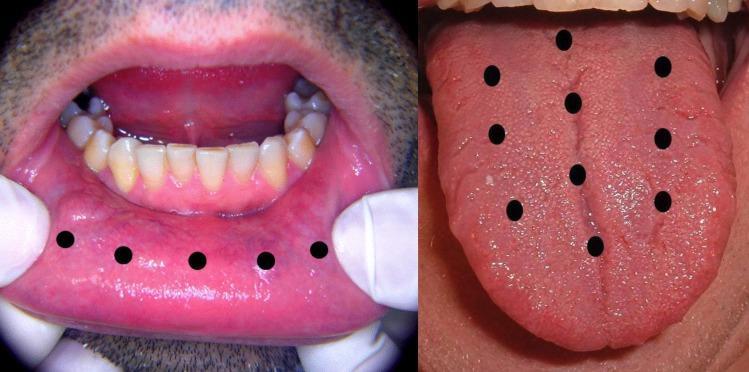
Two-panel clinical photograph and diagram illustrating a treatment protocol for oral conditions using Low-Level Laser Therapy (LLLT). The left panel shows an intraoral view of the lower labial mucosa being retracted. The mucosa appears healthy, pink, and moist. Five black circular markers are overlaid in a linear arrangement across the labial vestibule to indicate the standardized application points for the laser diode. The right panel displays the dorsal surface of the tongue, showcasing the median sulcus and normal filiform and fungiform papillae distribution. Ten black circular markers are superimposed on the tongue to denote specific LLLT application sites: four along the median sulcus and three on each lateral side of the midline. This visual serves as an educational guide for therapeutic mapping in the treatment of symptoms such as burning mouth syndrome or oral mucositis. The imagery belongs to the dental and oral medicine specialty, targeting clinical practitioners and students learning photobiomodulation techniques.
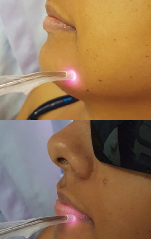
Two-panel clinical photograph demonstrating extraoral low-level laser therapy (LLLT) being applied to a patient's face for the treatment of post-surgical paresthesia. A handheld therapeutic laser device, covered in a sterile clear protective sheath for biosafety, is shown in direct contact with the skin. The first panel shows the application to the mental (chin) region, while the second shows application to the lower vermilion border and labial mucosa. A bright pinkish-red light is visible at the tip of the probe, indicating active irradiation targeting the pathways of the inferior alveolar and mental nerves. The patient is wearing protective eyewear as a safety protocol. This visual illustrates the clinical management of sensory deficits following third molar extraction, emphasizing non-invasive photobiomodulation techniques in oral and maxillofacial rehabilitation.
PMID: 39652213
PMID: 34654554
laser therapy tendinopathy lateral epicondylitis shoulder
PMID: 41964853
photobiomodulation laser fracture bone healing regeneration
laser photobiomodulation mechanism cytochrome c oxidase mitochondria cell diagram
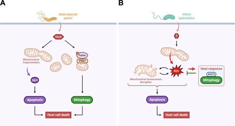
This pathophysiology diagram illustrates the signaling pathways through which extracellular pathogens, Helicobacter pylori and Vibrio splendidus, manipulate host mitochondrial homeostasis to induce cell death. Panel A details the H. pylori mechanism: the virulence effector VacA is introduced into the host cell, where it bifurcates into two pathways. One pathway causes mitochondrial fragmentation and cytochrome c (Cyt C) release, triggering apoptosis. The other activates the PINK1/Parkin-mediated mitophagy pathway. Both lead to host cell death. Panel B illustrates the V. splendidus pathway: infection triggers mitochondrial homeostasis disruption and the accumulation of mitochondrial reactive oxygen species (mtROS). This oxidative stress leads to host cell apoptosis. In response, a defensive host mechanism is shown where BNIP3-mediated mitophagy is initiated to eliminate damaged mitochondria and limit mtROS-induced cell death. The diagram highlights key educational concepts in medical microbiology and cellular pathology, specifically the intersection of mitochondrial stress, mitophagy, and programmed cell death during bacterial infection.
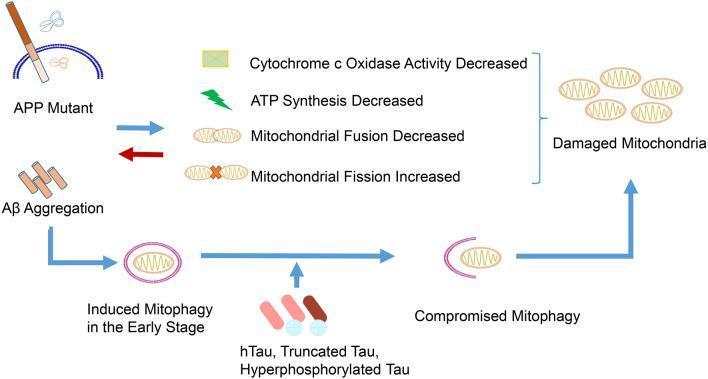
This pathophysiology diagram illustrates the bidirectional relationship between Alzheimer's disease (AD) pathologies and mitochondrial dysfunction. The flowchart begins with APP Mutant and Aβ Aggregation, which trigger a cascade of mitochondrial impairment, including decreased cytochrome c oxidase activity, decreased ATP synthesis, decreased mitochondrial fusion, and increased mitochondrial fission. These factors culminate in the accumulation of 'Damaged Mitochondria.' The diagram depicts a temporal progression of mitophagy: in the early stages, Aβ aggregation triggers 'Induced Mitophagy,' represented by a mitochondrion enclosed in a pink autophagosomal membrane. However, as the disease progresses, the accumulation of Tau variants (hTau, Truncated Tau, and Hyperphosphorylated Tau) interferes with this process, leading to 'Compromised Mitophagy'—visually indicated by an incomplete autophagosomal membrane. This failure in the mitophagic clearance pathway creates a vicious cycle, where uncleared damaged mitochondria further drive Aβ and Tau toxicity, ultimately contributing to neurodegenerative progression.
PMID: 42080480
PMID: 40016554
PMID: 37108257
Therapeutic Laser in Orthopaedics
1. Definition and Nomenclature
| Term | Notes |
|---|---|
| Low-Level Laser Therapy (LLLT) | Original term; "low level" refers to sub-thermal power |
| Photobiomodulation (PBM) | Current preferred term (NAALT/World Association consensus); encompasses both laser and LED |
| Photobiomodulation Therapy (PBMT) | Formal clinical term accepted by MeSH since 2002 |
| Cold Laser / Soft Laser | Non-thermal operation, colloquial |
| Biostimulation Laser | Emphasises anabolic/repair effects |
| High-Intensity Laser Therapy (HILT) | A separate category - higher power, still non-ablative, used clinically for musculoskeletal pain (distinguished from LLLT) |
2. Physical Principles
2.1 Laser Properties
- Monochromaticity - single wavelength
- Coherence - waves in phase (spatial and temporal)
- Collimation - minimal divergence; maintains intensity over distance
2.2 Wavelength and Tissue Penetration
| Wavelength Range | Spectrum | Tissue Penetration | Main Chromophore |
|---|---|---|---|
| 400-600 nm | Visible (blue-green) | Superficial (<1 mm) | Haemoglobin, melanin |
| 600-700 nm | Red (visible) | 1-3 mm | Cytochrome c oxidase |
| 780-860 nm | Near-infrared (NIR) | 3-5 cm | Cytochrome c oxidase, water |
| 900-1000 nm | NIR | Up to 5-7 cm | Water |
| >1100 nm | Mid-infrared | Superficial (water absorption) | Water |
- 632-670 nm (He-Ne, red diode): superficial soft tissue, wound healing
- 780-830 nm (GaAlAs diode): soft tissue, tendons, superficial joints
- 904-905 nm (GaAs pulsed): deep penetration, joint cartilage, bone - best evidence for knee OA
- 1064 nm (Nd:YAG): deepest penetration for HILT; muscle and deep joints
2.3 Dosimetry Parameters
| Parameter | Definition | Typical LLLT Range | Typical HILT Range |
|---|---|---|---|
| Wavelength (nm) | Light colour | 630-980 nm | 1064 nm (Nd:YAG) |
| Power (mW/W) | Instantaneous output | 5-500 mW | 1-25 W |
| Power density (mW/cm²) | Irradiance at tissue surface | 5-50 mW/cm² | 500-5000 mW/cm² |
| Energy (J) | Power × time | 0.5-4 J per point | 100-2000 J per session |
| Energy density (J/cm²) | Dose ("fluence") | 0.5-10 J/cm² | 30-300 J/cm² |
| Pulse frequency (Hz) | For pulsed devices | Continuous or 1-10,000 Hz | Pulsed or scanning |
| Treatment duration | Per session | 30 seconds - 10 minutes | 5-20 minutes |
| Application mode | How applied | Contact or non-contact | Scanning or contact |
3. Classification of Therapeutic Lasers
Class/Category System (IEC 60825-1)
| Class | Power | Risk | Examples |
|---|---|---|---|
| Class 1 | <0.39 mW | Safe under all conditions | Laser printers |
| Class 2 | 1 mW (visible only) | Low risk (blink reflex protective) | Laser pointers |
| Class 3R | 1-5 mW | Small risk | Some pointers |
| Class 3B | 5-500 mW | Risk of direct viewing | LLLT devices, most therapeutic lasers |
| Class 4 | >500 mW | Fire, skin, diffuse reflection hazard | HILT, surgical lasers |
LLLT vs HILT - Key Clinical Distinction
| Feature | LLLT / PBM | HILT (High-Intensity Laser) |
|---|---|---|
| Power | 5-500 mW | 1-25 W |
| Wavelength | 630-980 nm | Usually 1064 nm (Nd:YAG) |
| Application | Point-by-point or scan | Scanning/pulsed movement required |
| Temperature rise | None (<1°C) | Mild (controlled) |
| Penetration | Moderate | Deep (5-7 cm) |
| Session time | 5-15 min | 10-20 min |
| Evidence base | Larger (older) | Growing (newer) |
| Main use | Soft tissue, wounds | Deep musculoskeletal (LBP, OA, frozen shoulder) |
4. Mechanism of Action (Photobiomodulation)
Primary Photochemical Events
-
Photon absorption by cytochrome c oxidase (primary photoreceptor in red/NIR range)
- Causes conformational changes in the enzyme
- Reverses inhibition by nitric oxide (NO) - "photodissociation of NO"
- Increases electron transport chain activity
-
Increased ATP production
- Improved mitochondrial respiratory activity
- More cellular energy available for repair processes
-
Reactive Oxygen Species (ROS) modulation
- Low doses: transient ROS production acts as second messenger (hormesis)
- Stimulates antioxidant enzyme upregulation (SOD, catalase)
-
Nitric Oxide (NO) release
- Photodissociated NO diffuses from cytochrome c oxidase
- Causes local vasodilation
- Secondary messenger signalling for healing
Secondary Cellular Effects
| Effect | Mechanism | Clinical Relevance |
|---|---|---|
| Anti-inflammatory | Reduced NF-κB activation; decreased IL-1β, IL-6, TNF-α; increased IL-10 | Pain, joint swelling |
| Analgesic | Endorphin/enkephalin release; serotonin modulation; reduced bradykinin; c-fibre inhibition | Pain relief |
| Proliferation | Growth factor upregulation (TGF-β, PDGF, FGF, VEGF) | Tissue repair |
| Angiogenesis | VEGF upregulation | Wound healing, bone healing |
| Collagen synthesis | Fibroblast stimulation; increased procollagen | Tendon, ligament, scar |
| Osteoblast activation | BMP-2 upregulation; increased ALP activity | Bone regeneration |
| Neural effects | Nerve conduction velocity changes; CGRP modulation | Neuropathic pain |
| Immunomodulation | Mast cell activation; macrophage polarisation M2 | Wound healing, anti-infection |
The Arndt-Schulz Law (Hormesis)
5. Orthopaedic Applications and Evidence
5.1 Knee Osteoarthritis (Best Supported Indication)
LLLT for Knee OA
- Systematic review & meta-analysis (Oliveira et al. 2024, Physical Therapy, PMID: 38775202, 10 RCTs, 542 participants):
- PBM significantly reduced pain at rest vs placebo: MD -0.7 (95% CI -1.1 to -0.2), moderate effect size
- No significant benefit for Timed Up & Go Test
- Significant within-group improvements in Lequesne Index and gait
- Very low certainty of evidence - cannot recommend isolated use, but may complement other therapies
- Conclusion: may be used as an adjunct, not standalone treatment
Optimal Wavelength for Knee OA
- Network meta-analysis (Fan et al. 2024, Aging Clin Exp Res, PMID: 39367994, 13 RCTs, 673 participants):
- Overall LLLT superior to sham for pain (SMD = 0.96, p<0.05)
- Not superior for function or stiffness
- Best wavelength for pain: 904-905 nm (SUCRA 86.9%), followed by 785-850 nm
- Evidence quality: low to very low
HILT for Knee OA
- Systematic review (Ahmad et al. 2022, Physiotherapy, PMID: 34654554):
- Both LLLT+exercise and HILT+exercise effective vs exercise alone
- HILT+exercise showed higher efficacy for reducing pain, stiffness, and improving function vs LLLT+exercise (indirect comparison)
- Significant improvements in WOMAC, VAS, and functional tests with HILT
5.2 Tendinopathy
HILT for Tendinopathy
- Systematic review & meta-analysis (Hong et al. 2026, Lasers Med Sci, PMID: 41964853, 15 RCTs, 629 patients):
- Conditions: lateral epicondylitis (53%), rotator cuff tendinopathy (27%), others (20%)
- HILT significantly improved pain: MD -1.15 (95% CI -1.73 to -0.58) - exceeds MCID
- HILT improved disability: SMD -1.00 (95% CI -1.77 to -0.22)
- Site-specific effects: shoulder (rotator cuff) responded better (MD -2.54) than elbow (MD -0.91)
- Treatment effects peaked at 16 weeks - cumulative benefit over time
- Stress pain showed most substantial relief: MD -2.30
- Lateral epicondylitis (tennis elbow) - 830 nm or 1064 nm
- Rotator cuff tendinopathy - 830 nm, 904 nm
- Achilles tendinopathy - 780-830 nm
- Patellar tendinopathy - 780-830 nm
- De Quervain tenosynovitis - 630-780 nm
5.3 Neck Pain, Low Back Pain, and Frozen Shoulder
| Condition | HILT Effect on Pain (MD) | Effect Size (SMD) |
|---|---|---|
| Frozen shoulder | -2.23 cm VAS (95% CI: -3.3 to -1.2) | Significant |
| Knee OA | -1.9 cm (95% CI: -2.0 to -1.8) | Significant |
| Low back pain | -1.9 cm (95% CI: -2.9 to -1.0) | 1.1 (large) |
| Myofascial pain | -1.9 cm (95% CI: -2.6 to -1.2) | Significant |
| Neck pain | Large effect | SMD 2.1 (95% CI 1.2-3.0) |
| Temporomandibular disorders | Limited RCTs | Inconclusive |
| Plantar fasciitis | Limited RCTs | Emerging |
5.4 Fractures and Bone Healing
In Humans (Clinical)
- Systematic review & meta-analysis (Wang et al. 2026, Ann Med, PMID: 42080480, 12 studies, 9 meta-analysed):
- PBM significantly reduces short-term (1-week) pain: MD -0.74 (95% CI -1.00 to -0.47, p<0.0001, I²=0%)
- Significant improvement in grip strength at 4 weeks for upper limb fractures: MD 5.03 (95% CI 4.29-5.78)
- No significant long-term benefits (4-26 weeks) for pain or function
- No significant effect on bone healing clinically
- No side effects reported in any study
In Animal Models
-
Systematic review & meta-analysis (Hazrati et al. 2025, Lasers Med Sci, PMID: 40016554, 27 animal studies):
- Most individual studies reported positive effects of PBMT on fracture healing
- Meta-analysis: no significant effect on maximum fracture force or hydroxyapatite mineralisation (Raman peaks)
- 780 nm, 808 nm, and 830 nm were most studied; 4 J/cm² most common dose
- Most common sites: tibia > femur > mandible
-
Systematic review on bone healing (Berni et al. 2023, Int J Mol Sci, PMID: 37108257):
- In vitro and in vivo evidence for LLLT promoting angiogenesis, fracture healing, osteogenic differentiation of stem cells
- Mechanisms: upregulation of BMP-2, alkaline phosphatase, RUNX2, VEGF, TGF-β
- Dose-dependent effects; results vary by cell type and parameters
- Clinical translation still limited
Current Position on Bone Healing
5.5 Other Musculoskeletal Applications
| Condition | Evidence Level | Key Finding |
|---|---|---|
| Carpal tunnel syndrome | Moderate | 2025 meta-analysis showed NO significant pain benefit vs sham |
| Fibromyalgia | Moderate certainty | Fatigue improvement: eSMD 1.25 (umbrella review 2025) |
| Plantar fasciitis | Emerging | Positive RCTs with 904 nm and 1064 nm |
| Myofascial pain | Moderate | HILT effective; TrP inactivation |
| Wound healing (post-surgical) | Established | Enhanced fibroblast activity, collagen synthesis |
| Stress fractures | Limited | Animal data positive; human data sparse |
| Bone-on-implant | Emerging | Accelerates osseointegration peri-implant (animal data) |
| Post-op inflammation | Positive | Reduces oedema, bruising, scar formation |
| Peripheral neuropathy | Growing | Emerging evidence for DPN (2025 RCT positive) |
6. Devices Used in Orthopaedic Practice
LLLT Devices (Class 3B)
- Diode lasers: GaAlAs (780-870 nm), GaAs (904 nm) - most common
- He-Ne lasers: 632.8 nm - older, less portable
- LED clusters (LEDs, not strictly lasers but used as PBM): broad emission, lower coherence, cheaper
- Multi-probe arrays: multiple diode probes in one handpiece
HILT Devices (Class 4)
- Nd:YAG 1064 nm (e.g. BTL Super Inductive System, Gymna HIL, Diowave 810/980): most common in HILT; deep penetration
- Diode lasers at high power (5-25 W): used for deeper musculoskeletal conditions
Laser vs LED Distinction
| Feature | Laser | LED |
|---|---|---|
| Coherence | Coherent | Incoherent |
| Collimation | Yes | No (divergent beam) |
| Monochromaticity | True | Quasi-monochromatic |
| Power density at depth | Higher | Lower |
| Cost | Higher | Lower |
| Evidence base | Primary | Growing |
7. Treatment Protocol in Orthopaedic Practice
Application Techniques
-
Point application (trigger point / grid method)
- Probe placed in direct skin contact
- Grid of points mapped over the treatment area
- Each point treated for 30-60 seconds
- Used for tendons, small joints, trigger points
-
Scanning technique
- Probe moved continuously over treatment area
- Used for HILT to distribute higher energy safely
- Avoids focal heating at one point
-
Cluster probe / array
- Multiple LEDs/laser diodes in a single applicator
- Covers larger area; used for knee, shoulder, back
-
Intra-articular laser
- Experimental; direct joint irradiation via optical fibre
- Used in research settings for OA
General Protocol Template
| Variable | Recommendation |
|---|---|
| Sessions per week | 3-5 (acute); 2-3 (chronic) |
| Total sessions | 8-15 typical course |
| Duration per session | 5-20 minutes |
| Treatment interval | Can treat daily (not mandatory rest between sessions) |
| Eye protection | Mandatory for patient, therapist, bystanders (laser-rated goggles) |
| Skin contact | Preferred (avoids reflection losses at air-skin interface) |
8. Safety, Precautions, and Contraindications
Absolute Contraindications
- Malignancy in the treatment field (or suspected) - risk of stimulating tumour growth
- Pregnancy - direct irradiation over gravid uterus
- Over the thyroid gland (Class 4)
- Direct irradiation of eyes (retinal damage)
- Photosensitive conditions/medications (porphyria, certain drugs)
- Over haemorrhagic areas (active bleeding)
Relative Contraindications
- Epilepsy (flicker-sensitive; use non-pulsed mode)
- Active systemic infections
- Over growth plates in children (theoretical concern; low evidence)
- Over implanted electronic devices (pacemakers) - direct irradiation
- Dark/tattooed skin (higher absorption, focal heating risk)
- Corticosteroid injection within 48 hours (combined effect unknown)
Adverse Effects
- Rare and mild: transient erythema, flare of symptoms in first 24-48 hours (expected photobiological response - "post-treatment soreness")
- Skin burns (if Class 4 used incorrectly without scanning)
- Eye injury (if eye protection not used)
- No systemic adverse effects reported in any meta-analysis
9. Umbrella-Level Evidence Summary (2025)
- Knee OA disability: eSMD 0.65 (95% CI 0.14-1.15) ✓
- Fibromyalgia fatigue: eSMD 1.25 (95% CI 0.63-1.87) ✓
- Burning mouth syndrome pain: eSMD -0.92 ✓
10. Comparison with Other Physical Therapy Modalities
| Modality | Mechanism | Penetration | Best Evidence |
|---|---|---|---|
| Therapeutic Laser (PBM) | Photobiomodulation | Up to 5-7 cm (HILT) | Knee OA, tendinopathy, LBP |
| Ultrasound therapy | Thermal + non-thermal (cavitation) | 3-5 cm | Tendinopathy, wound healing |
| TENS | Neural gate theory; endorphin release | Superficial nerve | Acute/chronic pain |
| ESWT (shockwave) | Mechanotransduction; neovascularisation | 3-6 cm | Calcific tendinitis, plantar fasciitis, non-union |
| Interferential therapy | Deep electrical stimulation | 3-5 cm | Muscle pain, oedema |
| Therapeutic ultrasound | Thermal, cavitation | 3-5 cm | Soft tissue contracture |
| Magnetic therapy (PEMF) | Electromagnetic induction | Deep | Bone non-union, OA |
| Diathermy | Deep heating | 3-5 cm | Muscle spasm, contracture |
- Non-thermal (safe over implants, superficial nerves)
- Anti-inflammatory + anabolic (unique combined effect)
- Suitable over wounds and post-surgical scars
- Can be applied immediately post-injury
- No known drug interactions
11. Current Controversies and Limitations
-
Dosimetry heterogeneity: No universally accepted treatment protocol. Wavelength, power density, energy dose, and pulse frequency vary widely across studies, making comparison and pooling difficult.
-
Sham/placebo control difficulty: Blinding patients and operators is challenging; thermal sensation distinguishes active from sham in HILT trials.
-
Publication bias: Most meta-analyses identify likely positive publication bias; negative trials are less frequently published.
-
Lack of head-to-head comparisons: LLLT vs HILT vs sham vs other modalities rarely compared directly.
-
Optimal parameters unknown: Even for best-studied indication (knee OA), optimal wavelength/dose combination is not definitively established.
-
Short follow-up: Most trials follow up to 4-12 weeks; long-term benefits unclear.
-
Regulatory variation: FDA (USA) has cleared some LLLT devices for pain; CE-marked in Europe; listed as experimental by some payers (insurance).
12. Practical Summary for Orthopaedic Practice
| Indication | Recommended Type | Wavelength | Notes |
|---|---|---|---|
| Knee OA | LLLT or HILT | 904-905 nm (best), 785-850 nm | Adjunct to exercise; moderate evidence |
| Rotator cuff tendinopathy | HILT | 1064 nm or 830 nm | Best shoulder response; 16-week course |
| Lateral epicondylitis | HILT | 1064 nm or 830 nm | Exceeds MCID for pain |
| Low back pain | HILT | 1064 nm | Large effect size; spinal disorders best for HILT |
| Neck pain / frozen shoulder | HILT | 1064 nm | Best HILT evidence; MD -2.23 for frozen shoulder |
| Acute fracture pain | PBM | 780-940 nm | Reduces 1-week pain; no bone healing effect |
| Plantar fasciitis | LLLT/HILT | 904 nm or 1064 nm | Emerging evidence |
| Post-surgical wound | LLLT | 630-780 nm | Superficial; accelerates fibroblast activity |
| Achilles tendinopathy | LLLT | 780-830 nm | Positive RCTs; adjunct to eccentric exercise |
- Therapeutic laser is safe with minimal side effects
- Best used as an adjunct to exercise and physiotherapy, not as a standalone treatment
- HILT > LLLT for deep musculoskeletal conditions (OA, LBP, frozen shoulder)
- 904-905 nm is the optimal wavelength for knee OA based on network meta-analysis
- Evidence quality remains low-moderate for most orthopaedic indications; further high-quality trials needed
- Eye protection is mandatory during all therapeutic laser applications
- Oliveira S et al. "Effectiveness of Photobiomodulation in Reducing Pain and Disability in Patients With Knee OA." Phys Ther. 2024. PMID: 38775202
- Fan T et al. "Optimal wavelength of LLLT in treating knee OA: network meta-analysis." Aging Clin Exp Res. 2024. PMID: 39367994
- Ahmad MA et al. "LLLT and HILT as adjuncts to rehabilitation in knee OA: systematic review." Physiotherapy. 2022. PMID: 34654554
- Hong R et al. "Effectiveness of HILT for tendinopathy: systematic review and meta-analysis." Lasers Med Sci. 2026. PMID: 41964853
- de la Barra Ortiz HA et al. "Quality appraisal of systematic reviews on HILT for musculoskeletal pain: umbrella review." Lasers Med Sci. 2024. PMID: 39652213
- Son Y et al. "Effects of photobiomodulation on multiple health outcomes: umbrella review of RCTs." Syst Rev. 2025. PMID: 40770824
- Wang W et al. "Effect of photobiomodulation on pain and function in fractures: systematic review and meta-analysis." Ann Med. 2026. PMID: 42080480
- Hazrati P et al. "Effect of PBMT on fracture healing: meta-analysis of animal studies." Lasers Med Sci. 2025. PMID: 40016554
- Berni M et al. "Role of LLLT in Bone Healing: Systematic Review." Int J Mol Sci. 2023. PMID: 37108257
Give me detailed information on TENS therapy in orthopaedics
TENS transcutaneous electrical nerve stimulation musculoskeletal pain
TENS therapy orthopaedics mechanism types indications clinical evidence 2024 2025
PMID: 35167691
PMID: 36130064
PMID: 37991646
PMID: 39592440
TENS transcutaneous electrical stimulation knee osteoarthritis postoperative pain
PMID: 37030583
PMID: 41132422
TENS electrical stimulation knee osteoarthritis pain function
TENS postoperative pain arthroplasty total knee replacement
TENS transcutaneous electrical nerve stimulation electrode placement knee back pain device
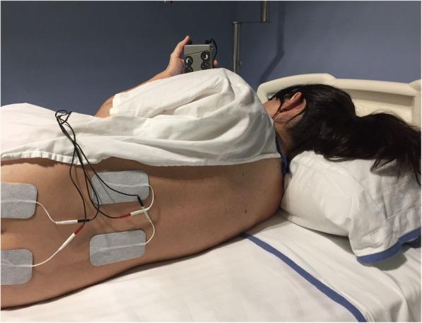
This clinical photograph demonstrates the electrode placement for Transcutaneous Electrical Nerve Stimulation (TENS) therapy in a patient lying in a lateral decubitus position. Four rectangular surface electrodes (approx. 5x9 cm) are applied to the lower back in a paravertebral arrangement. The superior pair is positioned at the T10–L1 level, and the inferior pair is at the S2–S4 level, targeting dermatomes relevant for obstetric pain relief during labour. Each electrode is connected via lead wires and color-coded connectors (red and white) to a handheld TENS unit held by the patient. The TENS unit is a dark, compact device featuring tactile dials for individual titration of stimulation intensity. This setup illustrates a non-pharmacological analgesic intervention used during the active phase of labour, where electrical impulses are utilized to modulate pain transmission through biphasic asymmetric or square waveforms.
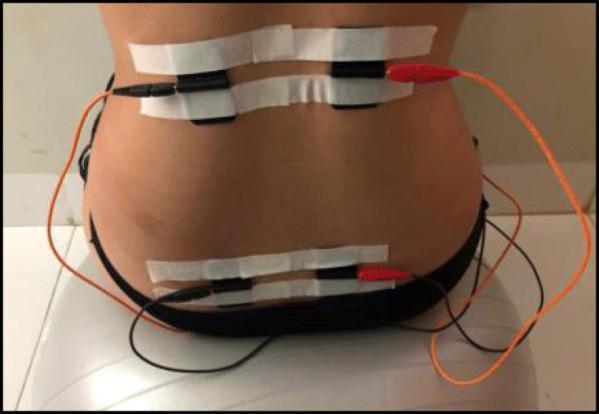
Clinical photograph demonstrating the electrode placement for Transcutaneous Electrical Nerve Stimulation (TENS) on the posterior trunk of a patient. Four black silicone electrodes are arranged in two horizontal pairs: a superior pair located in the thoracolumbar region (approximately T10–L1) and an inferior pair located in the sacral region (approximately S2–S4). The electrodes are secured to the skin using horizontal strips of white medical masking tape. Electrical leads are attached to each electrode, featuring a combination of black and orange wires that connect to a portable electrostimulation unit. This setup is typical for obstetric or physiotherapeutic pain management protocols, where the placement targets dermatomes associated with pelvic and lower back pain. The patient is shown in a seated position, likely on a therapeutic ball, consistent with labor pain management or pelvic floor rehabilitation settings.
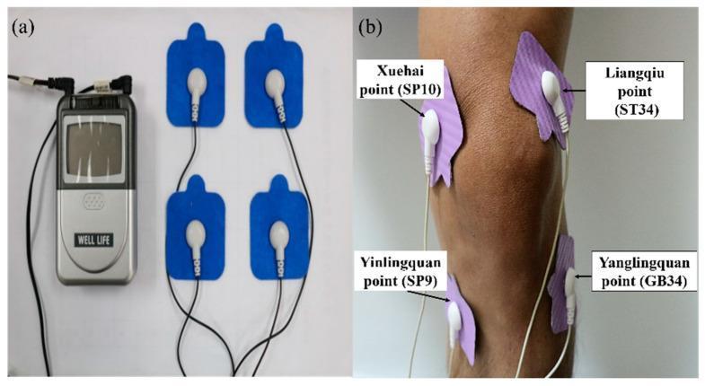
This procedural clinical photograph illustrates the application of Transcutaneous Electrical Nerve Stimulation (TENS) for knee pain management. Panel (a) shows the physical components: a handheld handheld TENS unit with a digital interface and control buttons connected via lead wires to four blue adhesive electrode pads. Panel (b) demonstrates clinical application on a patient's right knee. The four lavender-colored adhesive patches are strategically placed over specific acupuncture and anatomical landmarks to deliver electrical stimulation across the joint. The labeled electrode positions include the medial side points Xuehai (SP10) and Yinlingquan (SP9), and the lateral side points Liangqiu (ST34) and Yanglingquan (GB34). The setup is typical for non-invasive physical therapy interventions aimed at relieving chronic or acute knee pain, such as that caused by osteoarthritis, by modulating nerve signals through varying current frequencies and intensities.
PMID: 34971318
PMID: 42264808
PMID: 42040599
Transcutaneous Electrical Nerve Stimulation (TENS) in Orthopaedics
1. Definition and Overview
- Non-invasive and non-pharmacological
- Portable and self-administered by patients at home
- Safe with a well-established adverse effect profile
- Used as an adjunct to exercise, physiotherapy, and pharmacological management - not as a standalone treatment
2. Historical Background
| Year | Development |
|---|---|
| 1965 | Melzack and Wall propose the Gate Control Theory of pain - theoretical basis for TENS |
| 1967 | First clinical trials of electrical nerve stimulation for pain |
| 1970s | TENS devices commercialised; widely adopted in physiotherapy |
| 1974 | MeSH term "Transcutaneous Electric Nerve Stimulation" established |
| 1980s-90s | Endorphin release mechanism identified for low-frequency TENS |
| 2000s | Opioid tolerance with prolonged use described; dose and frequency protocols refined |
| Present | Evidence base consolidated; WHO, NICE, and OARSI guidelines developed |
3. Physical Parameters and Device Technology
3.1 Key Electrical Parameters
| Parameter | Definition | Range | Clinical Impact |
|---|---|---|---|
| Waveform | Shape of electrical pulse | Biphasic symmetrical/asymmetrical square wave (most common); monophasic | Biphasic preferred - no net DC charge, less skin irritation |
| Pulse width (duration) | Duration of each pulse | 50-500 µs | Determines fibre recruitment; narrow = Aβ fibres; wide = Aδ/C fibres |
| Frequency (Hz) | Pulses per second | 1-200 Hz | Determines mechanism of action (see modes below) |
| Intensity (mA) | Amplitude of current | 0-80 mA | Titrated to patient sensation/comfort |
| Modulation | Varying frequency/intensity over time | Burst, AM, FM | Reduces accommodation/tolerance |
| Phase charge | Pulse width × intensity | µC per pulse | Determines fibre selectivity |
3.2 Fibre Recruitment Hierarchy
- Sensory threshold: tingling/paresthesia without motor contraction (Aβ activation)
- Motor threshold: visible muscle twitch
- Pain threshold: uncomfortable but tolerable (used in certain protocols)
4. Types/Modes of TENS
4.1 Conventional TENS (High-Frequency TENS)
| Feature | Detail |
|---|---|
| Frequency | 80-150 Hz (high) |
| Pulse width | 50-200 µs (narrow) |
| Intensity | Sensory threshold (comfortable tingling; no muscle contraction) |
| Onset | Rapid (minutes) |
| Duration of effect | Short (ends with stimulation; 30-60 min post) |
| Mechanism | Gate Control Theory - Aβ fibre activation closes the pain gate in substantia gelatinosa (spinal cord dorsal horn) |
| Tolerance | Yes - decreases efficacy over time; address by varying parameters |
| Best for | Acute pain, post-surgical, breakthrough pain |
4.2 Acupuncture-Like TENS (Low-Frequency TENS / AL-TENS)
| Feature | Detail |
|---|---|
| Frequency | 1-10 Hz (low) |
| Pulse width | 200-300 µs (wide) |
| Intensity | Motor threshold or above (muscle twitching elicited) |
| Onset | Slow (20-30 min) |
| Duration of effect | Longer (30 min - several hours post-stimulation) |
| Mechanism | Activates hypothalamic-pituitary axis; releases β-endorphins, enkephalins, and dynorphins in CNS; blocked by naloxone |
| Tolerance | Less accommodation than conventional TENS |
| Best for | Chronic pain, musculoskeletal conditions |
4.3 Burst-Mode TENS
| Feature | Detail |
|---|---|
| Frequency | Bursts at 2-4 Hz, containing 100 Hz pulses within each burst |
| Intensity | Motor threshold |
| Mechanism | Combines opioid (low frequency burst) + gate control (high freq within burst) |
| Advantage | Better tolerated than high-intensity AL-TENS |
| Best for | Patients who cannot tolerate sustained motor twitching |
4.4 Intense TENS
| Feature | Detail |
|---|---|
| Frequency | 80-200 Hz |
| Intensity | High - produces strong, barely tolerable paresthesia |
| Duration | Short (15-30 min per session) |
| Mechanism | Activates Aδ fibres; stimulates descending pain inhibitory pathways (periaqueductal grey) |
| Best for | Acute pain, wound debridement, procedures |
4.5 Hyperstimulation TENS (Electroacupuncture)
- Needle electrodes at acupuncture points (technically percutaneous/PENS)
- Produces strong stimulation at specific myofascial trigger or acupuncture points
- Not traditional TENS (surface electrodes) but often grouped together
5. Mechanism of Action
5.1 Gate Control Theory (Melzack and Wall, 1965)
- Large-diameter myelinated Aβ fibres (carrying non-noxious sensory input: touch, vibration) and small-diameter Aδ/C fibres (carrying pain signals) both synapse on transmission cells (T-cells) in the substantia gelatinosa (Laminae I and V) of the dorsal horn
- Aβ fibre activation activates interneurons (SG cells) which pre-synaptically inhibit the pain signal before it reaches T-cells
- High-frequency TENS activates Aβ fibres → "closes the gate" → reduces nociceptive transmission to the brain
- Simultaneously, Aβ activation inhibits C-fibre transmission in the dorsal horn
5.2 Endogenous Opioid Release (Low-Frequency TENS)
- Low-frequency TENS (1-10 Hz) activates delta-opioid receptors primarily
- High-frequency TENS (80-150 Hz) activates mu-opioid receptors
- Naloxone (opioid antagonist) blocks the analgesic effect of low-frequency TENS - direct evidence for opioid mechanism
- Endorphins released in spinal cord and brain (rostral ventromedial medulla, periaqueductal grey)
5.3 Descending Pain Inhibition
- TENS activates descending inhibitory pathways from the brain stem
- Periaqueductal grey (PAG) → rostral ventromedial medulla (RVM) → dorsal horn
- Serotonin (5-HT) and norepinephrine are key neurotransmitters in this pathway
- Mid-term effects on conditioned pain modulation (CPM) improve with TENS - evidence for central sensitisation reduction
5.4 Effects on Central and Peripheral Sensitisation
-
Systematic review & meta-analysis (DeJesus et al. 2023, J Pain, PMID: 37030583, 58 studies, 35 meta-analysed):
- Meta-analyses favoured TENS for reducing primary hyperalgesia (local; high evidence) and secondary hyperalgesia (remote; moderate evidence)
- TENS reduces pain at rest and during movement in both chronic musculoskeletal pain and acute experimental pain
- Moderate evidence for reduction of both central and peripheral sensitisation
- Temporal summation and conditioned pain modulation were under-studied
-
Systematic review (Rodriguez Lagos et al. 2023, Pain Med, PMID: 36130064, 24 RCTs):
- Immediate effects on local pressure pain threshold (PPT): significant, moderate effect size (SMD 0.53, 95% CI 0.34-0.72)
- Mid-term effects on local PPT: significant, large effect size (SMD 0.55)
- Immediate effects on conditioned pain modulation: significant, large effect size (SMD 0.94)
- Short-term effects were not sustained vs control
- Suggests TENS modulates central pain mechanisms beyond pure peripheral gate-control
5.5 Other Mechanisms
- Peripheral vasodilatation: antidromic activation of sensory fibres releases vasoactive neuropeptides (substance P, CGRP) → local blood flow
- Muscle relaxation: reduces protective muscle spasm secondary to pain reduction
- Anti-inflammatory: some evidence for reduction of inflammatory markers in periarticular tissues
- Placebo effect: meaningful; must be accounted for in trial design
6. TENS vs PENS (Percutaneous Electrical Nerve Stimulation)
| Feature | TENS | PENS |
|---|---|---|
| Electrode type | Surface adhesive pads | Fine needles inserted into skin/subcutaneous tissue |
| Invasiveness | Non-invasive | Minimally invasive |
| Current delivery | Through skin resistance | Direct to nerve without skin impedance |
| Current efficiency | Lower (10-20% reaches nerve) | Higher |
| Application | Self-applied at home | Clinic-based only |
| Evidence comparison | Slightly less effective | Slightly more effective |
- PENS vs TENS: overall effect of PENS statistically but NOT clinically superior (MD = -1.0 cm; 95% CI: -1.5 to -0.4) with high heterogeneity (I²=76%)
- When only low risk-of-bias studies analysed: no clinically significant difference between TENS and PENS (MD -0.81 cm; 95% CI -1.6 to 0.02) - moderate GRADE evidence
- Conclusion: TENS can be recommended over PENS given equivalence in higher-quality studies plus non-invasive, self-administered advantages
7. Orthopaedic Indications and Evidence
7.1 Knee Osteoarthritis (Best-Studied Indication)
2022 Meta-Analysis
- Wu et al. 2022 (Clin Rehabil, PMID: 34971318, 14 RCTs, 1398 patients):
- Active TENS > sham TENS for VAS pain reduction
- TENS + other interventions > other interventions alone for VAS pain (short, medium, long term)
- TENS combination superior for WOMAC pain subscale (medium and long term)
- TENS combination superior for function (medium and long term)
- TENS not effective for stiffness
- TENS improved walking ability
2026 Meta-Analysis (Most Recent)
- Peng et al. 2026 (J Bodyw Mov Ther, PMID: 42264808, 21 RCTs, 20 meta-analysed):
- TENS significantly improved pain: MD = -0.82 (95% CI: -1.01 to -0.62) ✓
- TENS significantly improved total WOMAC score: MD = -4.76 (95% CI: -8.84 to -0.67) ✓
- TENS significantly improved knee extension muscle strength: MD = 7.39 (95% CI: 0.91-13.88) ✓
- TENS significantly improved knee flexion strength: MD = 4.72 (95% CI: 1.92-7.52) ✓
- No significant effects on stiffness, ROM, or 6-minute walk test
- Heterogeneity explained partly by TENS parameter variations
- Conclusion: "TENS effectively reduces pain and improves muscle strength in KOA; promising as adjunctive multimodal strategy"
Noninvasive Electrical Stimulation Comparison (2026)
- Cano-Orihuela et al. 2026 (Front Med, PMID: 42040599, 15 RCTs, 1137 patients):
- Compared tDCS, NMES, WB-EMS, TENS, CES, tVNS in knee OA
- TENS: most variable results; best short-term analgesia but limited beyond short-term
- tDCS: more consistent moderate analgesic effects
- NMES: better for quadriceps strength, mobility, patient-reported outcomes
- Conclusion: TENS useful for pain; NMES better for strength deficits
OARSI and ACR Position
- OARSI 2019 guidelines: TENS conditionally recommended for knee OA (evidence uncertain)
- ACR 2019 guidelines for hand/hip/knee OA: TENS conditionally recommended for knee OA
7.2 Chronic Low Back Pain
-
WHO Systematic Review (Verville et al. 2023, J Occup Rehabil, PMID: 37991646, 17 RCTs, n=1027, informing WHO guideline):
- TENS vs sham: marginal pain reduction in the immediate term (2 weeks): MD = -0.90 (95% CI: -1.54 to -0.26) - statistically significant but NOT clinically important
- TENS reduced pain catastrophizing at 3 months (MD -11.20)
- Little to no difference for function, disability, quality of life, or medication use
- All evidence: very low certainty (GRADE)
- WHO conclusion: benefit not established for chronic primary LBP
-
NICE UK guidelines (2021): Do not offer TENS for low back pain with or without sciatica as an isolated treatment
-
Clinical reality: TENS is widely used in LBP as adjunct despite weak isolated evidence; patient preference and safety justify continued adjunctive use
7.3 Neck Pain and Cervicogenic Pain
- Multiple RCTs show TENS reduces cervical pain VAS
- High-frequency (80-100 Hz) conventional TENS applied paravertebrally at C4-C6 level
- Used for cervical spondylosis, acute whiplash, cervicogenic headache
- Umbrella review evidence: HILT (not TENS) has largest effect size for neck pain; TENS evidence for neck pain remains limited
7.4 Postoperative Pain (Orthopaedic Surgery)
- Multiple RCTs support TENS for post-TKA pain management
- Reduces opioid consumption postoperatively
- Applied over the periincisional area; electrodes straddling the knee incision
- 2025 prospective RCT (Maeda et al., 3-arm: TENS vs MENS vs control post-TKA):
- TENS and MENS groups showed superior pain relief during walking vs control
- Administered from Day 3 post-op, 5×/week for 2 weeks
- Total hip arthroplasty
- Spinal surgery (postoperative)
- Shoulder arthroplasty / rotator cuff repair
- TENS reduces analgesic requirements, particularly opioids
7.5 Tendinopathy
- Lateral epicondylitis (tennis elbow): TENS applied over the lateral epicondyle; useful for acute/chronic pain
- Rotator cuff tendinopathy: paravertebral C5-C6 + local shoulder application
- Achilles/patellar tendinopathy: local electrode placement over tendon and muscle belly
- Evidence: mostly positive RCTs; moderate evidence; less robust than for OA
7.6 Fibromyalgia
- High-frequency TENS provides short-term pain relief in fibromyalgia
- Movement-evoked pain in fibromyalgia reduced by TENS applied during exercise
- Systematic review: TENS during physical activity reduces pain and improves exercise participation
7.7 TENS During Exercise ("Active TENS")
- Systematic review (de Espindula Brehm et al. 2024, Musculoskeletal Care, PMID: 39592440):
- High-frequency TENS at sensory threshold applied simultaneously with exercise produces more significant analgesic effects than exercise alone
- Enables patients to exercise with reduced pain, thus performing better rehabilitation
- Key finding: TENS applied during functional activity (not just at rest) is clinically superior
- Only 6 studies; methodology varies; more trials needed
7.8 Neuropathic Pain in Orthopaedic Practice
- Systematic review & meta-analysis (ElMeligie et al. 2025, Biomed Res Int, PMID: 41132422, 30 studies, 25 meta-analysed):
- TENS slightly reduced neuropathic pain vs placebo: SMD = -0.35 (not clinically significant, p=0.13)
- Spinal cord injury: TENS significantly superior to placebo for neuropathic pain (SMD = -1.14; 95% CI: -2.22 to -0.06, p=0.04)
- Diabetic neuropathy: similar to placebo and other electrotherapies
- Overall: small, clinically marginal effects for most neuropathic conditions
7.9 Other Orthopaedic Applications
| Condition | Use of TENS | Evidence Level |
|---|---|---|
| Rheumatoid arthritis | Pain control in joint flares | Limited |
| Acute fracture pain | Post-injury, post-manipulation | Moderate (adjunct) |
| CRPS Type I (Sudeck's) | Multi-modal pain management | Used clinically; moderate |
| Phantom limb pain | Post-amputation; mirror therapy adjunct | Moderate |
| Plantar fasciitis | Local heel/fascia electrodes | Small positive RCTs |
| Frozen shoulder | Periarticular; used in rehabilitation | Positive small RCTs |
| Post-spinal surgery | Adjunct to opioids, NSAIDS | Moderate positive |
| Sports injuries (acute) | Muscle sprains, strains | Short-term analgesia |
8. Electrode Placement Principles
General Rules
- Electrodes should be placed to direct the current through the painful area - the active electrode over the site of maximum pain, return electrode proximal or distal
- Never cross the heart - both electrodes on the same limb/side or ipsilateral trunk
- Electrodes should not touch each other - minimum 1-2 cm apart
- Skin must be intact - clean, dry skin; avoid wounds, rashes, open areas
Common Orthopaedic Electrode Placement Patterns
| Condition | Placement |
|---|---|
| Knee OA | Flanking the knee joint (medial + lateral); or around the patella |
| Low back pain | Paravertebral L3-S1 bilaterally; two pairs straddling the lumbar spine |
| Neck pain | Paravertebral C4-C6 bilaterally; or unilateral if unilateral pain |
| Shoulder/rotator cuff | Anterior + posterior shoulder over the glenohumeral joint |
| Lateral epicondylitis | Over lateral epicondyle and forearm extensor muscle belly |
| Achilles tendinopathy | Over Achilles tendon and gastrocnemius-soleus muscle belly |
| Post-TKA | Periincisional; flanking the knee incision laterally |
| Plantar fasciitis | Heel pad; plantar fascia (over the medial calcaneal tubercle) |
| Hip OA | Over greater trochanter and groin |
9. Treatment Parameters by Mode
| Mode | Frequency | Pulse Width | Intensity | Session Duration | Sessions/Week |
|---|---|---|---|---|---|
| Conventional | 80-150 Hz | 50-200 µs | Sensory (comfortable tingling) | 30-60 min | Daily |
| AL-TENS | 1-10 Hz | 200-300 µs | Motor (visible twitch) | 20-30 min | 3-5×/week |
| Burst | 2-4 Hz bursts (100 Hz internal) | 200 µs | Motor threshold | 20-30 min | 3-5×/week |
| Intense | 80-200 Hz | 200-500 µs | Strong; near-painful | 15-30 min | As needed |
10. Equipment
Types of TENS Devices
| Type | Features | Use |
|---|---|---|
| Portable (handheld) | Battery-powered; 2 or 4 channel; compact | Patient home use; most common |
| Clinical/bench-top unit | Larger; more precise parameter control; multiple channels | Physiotherapy clinic |
| Wireless TENS | No lead wires; Bluetooth-controlled via app (e.g. iReliev, Quell) | Patient convenience |
| Wearable TENS | Integrated into garment (e.g. knee sleeve with embedded electrodes) | Knee OA; easy self-application |
| Water-bath TENS | Limb immersed in water with electrodes (hydrogalvanic) | Hands, feet (RA, neuropathy) |
| PENS device | Acupuncture needles as electrodes; clinic-only | Chronic deep pain |
Electrode Types
- Self-adhesive hydrogel pads: most common; reusable 5-10 times
- Carbon rubber electrodes with gel: reusable, better current distribution
- Stick-on patches: single-use; convenient for home
- Sizes: 5×5 cm (standard), 5×9 cm (large back), 2×2 cm (small joints)
11. Safety Profile, Contraindications, and Precautions
Absolute Contraindications
| Contraindication | Reason |
|---|---|
| Pacemaker or implanted cardiac device | Electrical interference with device function; arrhythmia risk |
| Pregnancy (over gravid uterus or lumbar/sacral area) | Risk of initiating premature labour or fetal harm |
| Active malignancy in the treatment field | Risk of stimulating tumour vascularity/metastasis |
| Thrombosis (DVT) in the treatment area | Risk of dislodging thrombus |
| Skin with altered or absent sensation (without precaution) | Cannot detect burns; especially at intensity thresholds |
| Epilepsy (electrodes near head or neck) | Risk of triggering seizures |
| Application to anterior neck | Risk of laryngospasm; adverse carotid response |
| Carotid sinus area | Vasovagal response; syncope |
| Transcerebrally (across both sides of the head) | Risk of ventricular fibrillation |
Relative Contraindications / Precautions
- Recent surgical incision (wait for wound closure)
- Dermatological conditions, rash, or broken skin
- Metal implants in treatment area (not an absolute CI; current flows around metal)
- Active infection (local)
- Known cardiac arrhythmia
- Children under 3 years (theoretical; limited evidence)
Adverse Effects
- Skin irritation / contact dermatitis - most common; from electrode gel or adhesive; usually self-limiting
- Burns - rare; only if defective equipment, very high intensity, or prolonged application on anaesthetic skin
- Hypersensitivity to electrode gel (allergy)
- Transient increase in pain - possible in first 1-2 sessions; resolves
- No systemic adverse effects documented at therapeutic intensities
- Tolerance/accommodation - analgesic effect diminishes with prolonged same-parameter use; managed by varying parameters
12. Comparison with Other Physical Therapy Modalities for Pain
| Modality | Mechanism | Penetration | Evidence vs TENS |
|---|---|---|---|
| TENS | Gate control + opioid + central inhibition | Peripheral nerve | Established; variable by indication |
| Interferential Therapy (IFT) | Two medium-frequency currents beat to produce low-frequency current deep in tissue | Deeper (3-5 cm) | Similar or slightly superior for deep pain; one meta-analysis IFT > TENS for MSK pain |
| NMES/EMS | Muscle contraction; strength gain | Muscle | Superior for quadriceps weakness (OA, post-TKA) |
| Ultrasound therapy | Thermal + cavitation | 3-5 cm | Different mechanism; useful for soft tissue contracture |
| Therapeutic laser | Photobiomodulation; ATP production | Up to 7 cm (HILT) | HILT > TENS for deep OA and tendinopathy (direct comparison limited) |
| ESWT | Mechanotransduction; neovascularisation | 3-6 cm | Superior for calcific tendinitis, non-union |
| PEMF | Electromagnetic bone stimulation | Deep | Superior for bone non-union; different indication |
| Acupuncture | Needle + endorphin release | Point-specific | Comparable efficacy; similar endorphin mechanism |
Interferential Therapy (IFT) vs TENS
- Systematic review (Hussein et al. 2022, Am J Phys Med Rehabil, PMID: 34469914):
- IFT significantly reduces pain in MSK conditions
- IFT claimed to penetrate deeper than TENS (two kHz-range currents cross and beat at low frequency within tissue)
- Both are commonly used as adjuncts in MSK practice
- Direct head-to-head: mixed; IFT may be marginally better for deep structures (hip, lumbar spine)
13. Evidence-Based Summary by Orthopaedic Indication
| Indication | Recommended | Evidence Quality | Key Guideline |
|---|---|---|---|
| Knee OA | Yes - adjunct | Moderate | OARSI/ACR: conditionally recommended |
| Acute musculoskeletal pain | Yes - adjunct | Moderate | Widely used clinically |
| Chronic LBP | Uncertain | Very low (WHO 2023) | NICE: do not offer isolated; WHO: marginal benefit only |
| Postoperative pain (TKA/THA) | Yes - adjunct | Moderate | Reduces opioid use |
| Neuropathic pain (SCI) | Yes | Moderate | TENS significantly effective in SCI-neuropathy |
| Neuropathic pain (DPN) | Uncertain | Low | Not superior to placebo |
| Neck pain | Probable - adjunct | Low-moderate | Used clinically; guideline support varies |
| Tendinopathy | Yes - adjunct | Low-moderate | Adjunct to exercise |
| Fibromyalgia | Yes - adjunct | Moderate | Improves movement-evoked pain |
| CRPS | Multi-modal only | Limited | Part of multi-modal rehab |
| Phantom limb pain | Probable | Limited | Small positive trials |
14. Key Practical Points for Orthopaedic Practice
-
TENS should not be used in isolation - it is an adjunct to exercise, physiotherapy, and appropriate medications; studies show TENS + exercise consistently outperforms TENS alone
-
Activate TENS at sensory threshold (tingling, no pain, no muscle contraction) for conventional mode - patient should report comfortable, non-painful sensation
-
Vary parameters to prevent tolerance - switching between conventional and burst mode across sessions helps maintain efficacy
-
Simultaneous use during exercise may be superior to pre/post-exercise application alone (per 2024 systematic review)
-
Teach patients for home use - TENS is one of the few physiotherapy modalities that patients can safely self-administer; empowers self-management, reduces clinic visits
-
For postoperative pain: start from day 1-3 post-op; periincisional application effective; reduces opioid requirements and side effects
-
For knee OA: use 4-electrode configuration flanking the joint; high-frequency (80-100 Hz) conventional mode; 30-45 minutes per session; 5×/week
-
Electrode placement is critical: if the first placement is ineffective, reposition electrodes to bracket the pain site differently
-
Duration of treatment: minimum 4-week course; effects may take 2-4 weeks to become apparent (central mechanisms)
-
Document parameters: record frequency, pulse width, intensity, electrode placement, and patient response for reproducibility
15. Current Controversies
-
Lack of dosimetry standardisation: no universally agreed optimal frequency, pulse width, or intensity for any orthopaedic condition; this is the primary reason for heterogeneity across trials
-
Sham TENS design problems: some "sham" TENS devices still deliver sub-sensory current; adequate placebo blinding is difficult
-
Short trial durations: most trials are 2-8 weeks; long-term efficacy data are scarce
-
Industry-driven heterogeneity: different devices produce different waveforms marketed as "TENS" despite physical differences
-
Who responds to TENS?: emerging evidence suggests responders have different pain phenotypes (lower central sensitisation may respond better to conventional TENS; higher central sensitisation may need lower frequency/opioid pathway activation)
-
NICE 2021 LBP guideline: controversy in UK physiotherapy community around NICE removing TENS recommendation for LBP; many clinicians continue to use it as an adjunct given safety and patient benefit in individual cases
- Wu Y et al. "Effects of TENS in people with knee OA: systematic review and meta-analysis." Clin Rehabil. 2022. PMID: 34971318
- Peng Y et al. "Neuromodulation through TENS in knee OA: systematic review and meta-analysis." J Bodyw Mov Ther. 2026. PMID: 42264808
- Cano-Orihuela M et al. "Noninvasive electrical stimulation in knee OA: systematic review and meta-analysis." Front Med. 2026. PMID: 42040599
- Verville L et al. "WHO CPG systematic review: TENS for chronic primary LBP." J Occup Rehabil. 2023. PMID: 37991646
- Beltran-Alacreu H et al. "Percutaneous vs transcutaneous electrical nerve stimulation for MSK pain: systematic review and meta-analysis." Pain Med. 2022. PMID: 35167691
- Rodriguez Lagos L et al. "Effects of PENS and TENS on endogenous pain mechanisms: systematic review and meta-analysis." Pain Med. 2023. PMID: 36130064
- DeJesus BM et al. "Effect of TENS on pain-related quantitative sensory tests in chronic MSK and acute experimental pain: systematic review and meta-analysis." J Pain. 2023. PMID: 37030583
- de Espindula Brehm T et al. "Effects of TENS during functional activities or exercise: systematic review." Musculoskeletal Care. 2024. PMID: 39592440
- ElMeligie MM et al. "Neuropathic pain relief through TENS: systematic review and meta-analysis." Biomed Res Int. 2025. PMID: 41132422
- Hussein HM et al. "Interferential current for musculoskeletal pain: systematic review and meta-analysis." Am J Phys Med Rehabil. 2022. PMID: 34469914
Give me detailed information on titanium alloys in orthopedics. Don't give any meta-analysis or research data.
titanium alloys orthopaedic implants Ti-6Al-4V properties types applications 2024 2025
https://www.frontiersin.org/journals/bioengineering-and-biot…
titanium alloy orthopaedic implant hip knee total joint replacement plate screw
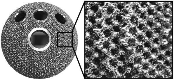
This orthopaedic clinical photograph displays the SQRUM TT acetabular socket, a prosthetic component used in Total Hip Arthroplasty (THA). The implant is made from a titanium alloy (Ti6Al4V) and exhibits a spherical shape with a specialized tridimensional, multiplane porous structure created via electron beam melting. The left portion of the image shows the macroscopic view of the hemispherical cup, featuring one central large circular opening and four smaller peripheral openings for screw fixation. The right portion provides a high-magnification inset of the surface, revealing a repeating hexagonal lattice with a porosity of 60% and a pore size of 640 μm. This textured, interconnected framework is designed to mimic natural cancellous bone, facilitating biological secondary fixation through bone ingrowth. The surface morphology appears rough and granular, optimized to provide initial stability and long-term osteointegration in patients with hip conditions such as osteonecrosis or osteoarthritis.
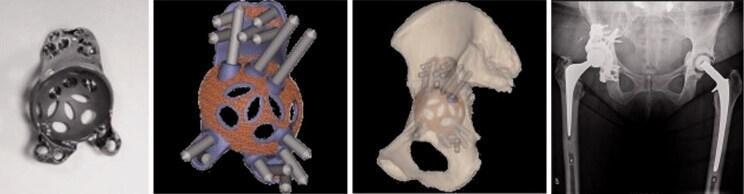
This composite figure illustrates the workflow for custom acetabular reconstruction in complex revision total hip arthroplasty. From left to right: The first panel shows a 3D-printed, patient-specific monobloc cup-cage titanium implant featuring a porous trabecular surface for biological fixation and multiple peripheral flanges with screw holes. The second panel displays a digital 3D planning model showing the intended screw trajectories through the implant into the surrounding pelvic bone. The third panel shows the implant integrated into a 3D CT-reconstructed model of the patient's hemipelvis, demonstrating preoperative planning for anatomical fit and center of rotation. The final panel is a postoperative anteroposterior (AP) pelvic radiograph confirming the successful bilateral hip replacement. The right hip demonstrates the custom-made acetabular cup-cage construct secured with multiple radiopaque screws, addressing a significant acetabular bone defect, alongside a prosthetic femoral stem. This visual demonstrates the application of computer-aided design (CAD) and additive manufacturing in orthopaedic surgery for treating Paprosky-type acetabular defects.
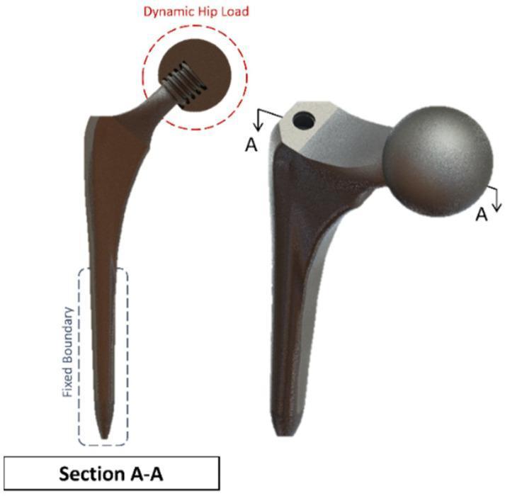
This orthopaedic engineering diagram illustrates a 3D model and cross-sectional view of a Summit hip implant used in Total Hip Replacement (THR) surgery. The visual highlights the structural components of the femoral prosthesis, including the elongated, tapered femoral stem, the neck, and the spherical femoral head (ball joint). On the left, a longitudinal cross-section (Section A-A) reveals the internal screw threads within the head-neck junction, facilitating mechanical stability. Annotations indicate biomechanical simulation parameters: a 'Fixed Boundary' is designated along the distal portion of the stem where it would be anchored within the femur, and a 'Dynamic Hip Load' is applied at the spherical head to simulate physiological articulation and stress distribution. This model is utilized in finite element analysis (FEA) to study stress concentrations, material fatigue, and the integration of SAW sensors for long-term implant monitoring. The diagram serves as an educational resource for medical students and biomedical engineers focusing on orthopaedic biomechanics and prosthesis design.
beta titanium alloys Ti-Nb-Zr orthopaedic stress shielding surface modification osseointegration 3D printing
porous titanium 3D printed orthopaedic spinal interbody cage trabecular bone ingrowth
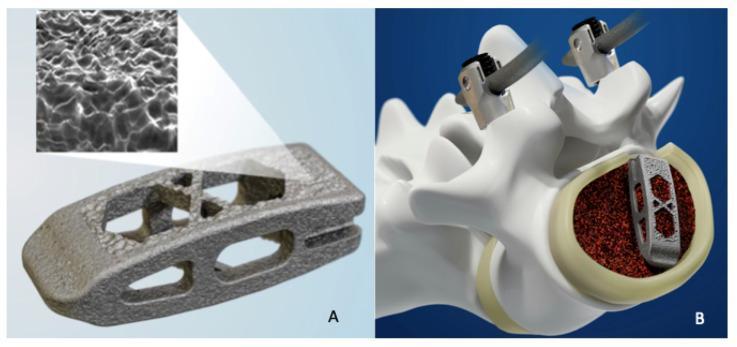
This medical illustration consists of two panels showcasing 3D-printed titanium spinal interbody fusion technology. Panel A presents a high-resolution view of a 3D-printed titanium cage, featuring a porous, lattice-based architecture designed for osseointegration. A magnified inset highlights the micro-topography of the surface, showing a roughened, irregular texture characteristic of powder bed fusion manufacturing, which enhances cellular adhesion. The cage exhibits a wedge-shaped profile with a central 'X' strut configuration and lateral apertures to accommodate bone graft material. Panel B is a clinical diagram showing the cage’s interbody placement within a lumbar vertebral segment. The cage is embedded within a bed of granular bone graft (represented in dark red) inside the vertebral body to facilitate arthrodesis. The diagram also illustrates surgical instrumentation (pedicle screw components) attached to the posterior elements of the vertebrae, providing a comprehensive view of the mechanical and biological integration required for spinal fusion procedures.
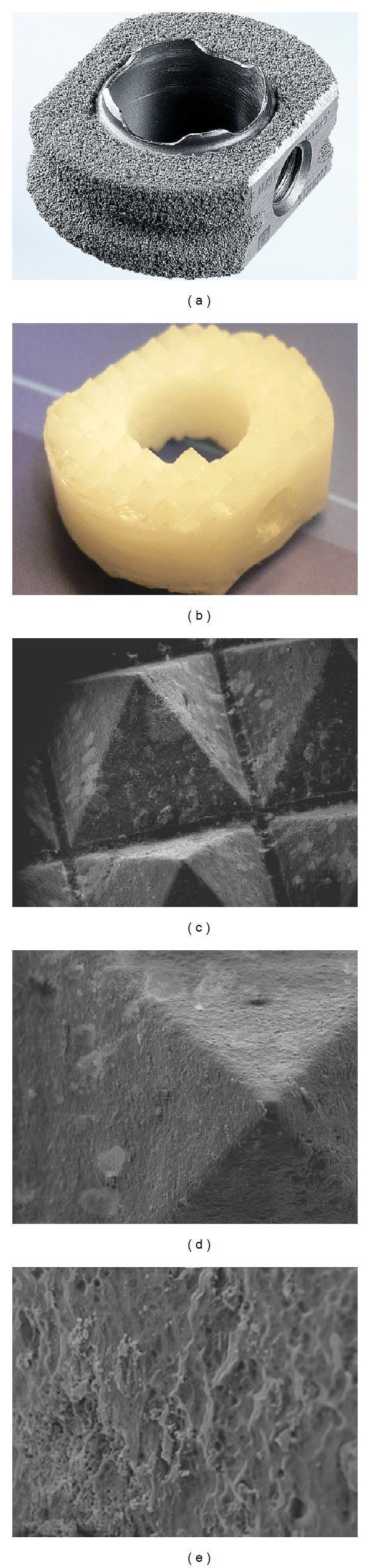
This composite educational image illustrates orthopedic spinal implants used in interbody fusion studies. (a) Displays a CeSpace Titanium Plasmapore cage, a clinical-grade control implant featuring a metallic gray, highly porous surface designed to enhance primary fixation and bone ingrowth. (b) Shows a bioresorbable Poly-(70L/30DL)-lactide-fiber-reinforced β-tricalcium phosphate (PLA70/β-TCP) composite cage, exhibiting a yellowish-white, ring-shaped structure with molded sharp ridges for vertebral endplate engagement. (c, d, e) Provide a series of Scanning Electron Micrographs (SEM) of the PLA70/β-TCP matrix at 35X, 100X, and 500X magnifications, respectively. These micrographs demonstrate the progressive visibility of the surface topography, showing ceramic particles embedded within the polymer matrix. At higher magnifications, the lack of an isolating film is evident, revealing a highly irregular, porous micro-texture that facilitates direct interaction between the bioactive ceramic particles and surrounding biological fluids. The material is designed for biomechanical stability and subsequent osteoconductivity in surgical applications.
Titanium Alloys in Orthopaedics
1. Introduction
2. Basic Properties of Titanium
Physical and Chemical Properties
| Property | Titanium (Pure) | Clinical Significance |
|---|---|---|
| Atomic number | 22 | - |
| Density | 4.51 g/cm³ | ~57% the weight of stainless steel |
| Melting point | 1668°C | High-temperature processing possible |
| Crystal structure | α (HCP below 882°C), β (BCC above 882°C) | Determines alloy classification |
| Oxide layer | TiO₂ (spontaneous, 2-10 nm) | Key to corrosion resistance and biocompatibility |
| Colour | Silver-grey | - |
Comparison with Other Orthopaedic Metals
| Property | Pure Ti | Ti-6Al-4V | Stainless Steel 316L | Cobalt-Chrome | Cortical Bone |
|---|---|---|---|---|---|
| Density (g/cm³) | 4.51 | 4.43 | 7.9 | 8.3 | 1.8-2.0 |
| Elastic modulus (GPa) | 100-105 | 110-114 | 193-200 | 210-253 | 15-25 |
| Yield strength (MPa) | 170-480 | 795-1000 | 170-750 | 450-1500 | 130-180 |
| UTS (MPa) | 240-550 | 860-1100 | 480-1000 | 655-1900 | 130-200 |
| Fatigue strength (MPa) | 300-700 | 500-750 | 315-700 | 300-900 | 60-120 |
| Corrosion resistance | Excellent | Excellent | Good | Very good | N/A |
| Biocompatibility | Excellent | Excellent | Good | Moderate | N/A |
| MRI compatibility | Excellent | Excellent | Poor | Poor | N/A |
3. Classification of Titanium Alloys
3.1 Alpha (α) Phase Alloys
- Pure titanium (CP-Ti, commercially pure) and alloys dominated by α-stabilisers (Al, O, N, C)
- Crystal structure: Hexagonal close-packed (HCP) at room temperature
- Properties: Good corrosion resistance, moderate strength, poor machinability
- Grades: CP-Ti Grades 1-4 (increasing oxygen content → increasing strength)
- Orthopaedic use: Dental implants, some bone screws; limited for high-load orthopaedic applications
3.2 Alpha-Beta (α+β) Alloys - THE CLINICAL WORKHORSE
- Contain both α-stabilisers (Al) and β-stabilisers (V, Mo, Nb, Zr)
- Most important alloy: Ti-6Al-4V (Grade 5)
- Dual-phase microstructure gives superior strength and machinability
- Used in the vast majority of orthopaedic metal implants worldwide
3.3 Beta (β) Phase Alloys - EMERGING GENERATION
- β-stabilisers predominate (Nb, Mo, Zr, Ta, Fe, Cr)
- Crystal structure: Body-centred cubic (BCC) - stable at room temperature with sufficient β-stabiliser
- Key advantage: Much lower elastic modulus (55-85 GPa) - closer to bone (15-25 GPa)
- Important alloys: Ti-13Nb-13Zr, Ti-15Mo, Ti-12Mo-6Zr-2Fe (TMZF), Ti-24Nb-4Zr-7.9Sn (TiNbZrSn), Ti-Nb-Ta-Zr
- Orthopaedic significance: Reduces stress shielding; the future direction of orthopaedic titanium development
4. The Workhorse: Ti-6Al-4V (Grade 5)
Composition
- Titanium: 89-91% (balance)
- Aluminium: 5.5-6.5% (α-stabiliser; increases strength)
- Vanadium: 3.5-4.5% (β-stabiliser; improves ductility and processability)
- Small amounts of oxygen, nitrogen, carbon, iron (controlled interstitials)
Role of Alloying Elements
| Element | Role | Effect |
|---|---|---|
| Aluminium (6%) | α-phase stabiliser | Increases yield strength, reduces density |
| Vanadium (4%) | β-phase stabiliser | Improves ductility, crack resistance, machinability |
Key Mechanical Properties (Ti-6Al-4V)
| Property | Value |
|---|---|
| Elastic modulus | 110-114 GPa |
| Yield strength | 795-1000 MPa |
| Ultimate tensile strength (UTS) | 860-1100 MPa |
| Fatigue strength (10⁷ cycles) | 500-750 MPa |
| Elongation at fracture | 8-15% |
| Hardness (Vickers) | 310-350 HV |
| Density | 4.43 g/cm³ |
Ti-6Al-4V ELI (Extra Low Interstitials, Grade 23)
- Reduced oxygen (<0.13%), nitrogen, carbon, and iron content
- Enhanced ductility and fracture toughness
- Preferred for medical implants where fatigue loading is critical (femoral stems, intramedullary nails)
- Better cold workability
5. Biocompatibility Mechanisms
5.1 The Titanium Oxide Layer (TiO₂)
- Forms within milliseconds of surface exposure to oxygen or moisture
- Self-repairing: if scratched or disrupted, the oxide layer re-forms immediately
- Acts as a chemical barrier preventing direct metal-tissue contact
- Prevents ion release into surrounding tissue
- The TiO₂ surface has a negative charge at physiological pH - promotes protein adsorption and cell attachment
- TiO₂ is chemically inert - no toxic ion leaching under normal conditions
5.2 Protein Adsorption and Cellular Interactions
- Protein adsorption (within seconds of implantation): fibronectin, vitronectin, and other extracellular matrix proteins adsorb onto the TiO₂ surface
- Cell attachment: osteoblasts, fibroblasts, and endothelial cells recognise adsorbed proteins via integrin receptors
- Osteoblast activity: titanium surfaces promote osteoblast proliferation, differentiation, and mineralisation
- Macrophage response: titanium elicits a mild, manageable foreign body response compared to other metals
5.3 Osseointegration
- Unique to titanium among common metallic biomaterials - cobalt-chrome is biologically inert and does not osseointegrate directly
- The TiO₂ layer allows bone to grow into direct contact with the metal surface
- Calcium and phosphate ions from body fluids deposit on TiO₂, forming a calcium titanate and calcium phosphate interlayer that chemically bonds to bone
- Porous and roughened surfaces dramatically enhance osseointegration by increasing surface area and providing scaffold for bone ingrowth
6. The Critical Issue: Stress Shielding
Definition
The Modulus Mismatch Problem
| Material | Elastic Modulus | Mismatch vs Cortical Bone |
|---|---|---|
| Stainless steel | 193-200 GPa | ~10× |
| Cobalt-chrome | 210-253 GPa | ~11-13× |
| Ti-6Al-4V | 110-114 GPa | ~5-6× |
| β-Ti alloys | 55-85 GPa | ~3-4× |
| β-Ti (low modulus) | 40-55 GPa | ~2-3× |
| Cortical bone | 15-25 GPa | Reference |
| Trabecular bone | 0.1-5 GPa | - |
Solutions to Stress Shielding
- Use β-type Ti alloys (lower modulus: 55-85 GPa)
- Porous/lattice structures - reduce effective modulus to match bone
- Additive manufacturing - engineered porous geometry with controlled porosity
- Tapered implant design - gradual load transfer
- Flexible intramedullary nail designs - slotted, thinner cross-sections
7. Orthopaedic Applications
7.1 Fracture Fixation
Intramedullary Nails
- Virtually all modern intramedullary nails are Ti-6Al-4V
- Advantages over stainless steel nails:
- ~50% lower elastic modulus → reduced stress concentration at nail tip
- Lighter weight
- MRI compatibility (post-op imaging possible)
- Better corrosion resistance at nail-bone interface
- Tapered nail tip and rounded distal geometry reduce stress risers
- Examples: Synthes Expert Nail, Stryker T2, Smith & Nephew Trigen
Plates and Screws
- Titanium alloy plates (Ti-6Al-4V or CP-Ti) for periarticular, distal radius, foot and ankle fixation
- Lower stiffness than stainless steel → reduced stress at plate ends → lower risk of refracture
- Screws: Ti-6Al-4V cortical, cancellous, locking screws
- Limitation: titanium is softer than cobalt-chrome and stainless steel → more susceptible to galling (thread damage); avoid mixing titanium and stainless steel hardware (galvanic corrosion)
External Fixators
- Pins and rings in titanium for MRI-compatible circular fixators (especially Ilizarov rings)
- Carbon fibre external fixator bodies with titanium pins
7.2 Total Joint Arthroplasty
Total Hip Arthroplasty (THA)
- Cementless titanium stems rely on osseointegration for fixation
- Porous coating (sintered beads, plasma spray, electron beam melting trabecular metal) provides scaffold for bone ingrowth
- Modulus closer to cortical bone than cobalt-chrome → less proximal stress shielding
- Survival: ~94% at 15 years for cementless titanium stems
- Hemispherical press-fit cups with porous outer surface
- Screw holes for supplementary fixation
- Bears polyethylene, ceramic, or metal bearing liners
Total Knee Arthroplasty (TKA)
- Tibial trays: titanium alloy (Ti-6Al-4V); excellent for cementless fixation
- Femoral components: Cobalt-chrome (preferred for the articulating bearing surface due to higher hardness)
- Patellar component: polyethylene (all-poly) or titanium-backed
- Hybrid TKA: titanium tibial tray + cobalt-chrome femoral component is the standard combination
7.3 Spinal Implants
Pedicle Screws and Rods
- Ti-6Al-4V pedicle screws: standard across most systems
- Titanium rods: available alongside cobalt-chrome; slightly more flexible
- MRI advantage: titanium produces markedly less artefact than cobalt-chrome or stainless steel - critical for post-op neurological assessment
Interbody Cages (IBF)
- Ti-6Al-4V or porous titanium interbody cages (TLIF, PLIF, ALIF, XLIF)
- Porous titanium cages allow bone ingrowth through the implant
- 3D-printed trabecular titanium cages (e.g. Stryker TRITANIUM®, DePuy Actis) achieve 70% porosity with gyroid or diamond lattice structures
Dynamic Stabilisation Rods
- Titanium rods with engineered flexibility for dynamic stabilisation
- Balance between mobility preservation and mechanical stability
7.4 Shoulder and Upper Extremity
- Shoulder arthroplasty: titanium glenoid baseplate (reverse shoulder); titanium humeral stems
- Distal radius plates: low-profile titanium locking plates (Ti-6Al-4V)
- Proximal humerus: titanium PHILOS plates, nail-plate devices
- Elbow, wrist, hand: titanium mini-plates and screws
7.5 Foot and Ankle Surgery
- Titanium hindfoot fusion nails, ankle plates
- Metatarsal and midfoot screws
- Titanium staples for arthrodesis
7.6 Trauma - Specific Examples
- Proximal femur: Cephalomedullary nails (Ti-6Al-4V): Gamma nail, PFNA, TFN
- Tibial nail: Ti-6Al-4V
- Humeral nail: Ti-6Al-4V
- Distal femur plate: Ti-6Al-4V LISS plate
- Calcaneal plate: Ti-6Al-4V
8. Porous Titanium - Mimicking Cancellous Bone
8.1 Rationale
8.2 Types of Porous Titanium Surfaces
| Method | Pore Size | Porosity | Clinical Use |
|---|---|---|---|
| Sintered bead coating | 250-500 µm | 30-35% | Early cementless components; still widely used |
| Plasma-spray coating | 100-300 µm | 30-40% | Hip stems, acetabular cups |
| Fibre metal mesh | 100-400 µm | 40-50% | Acetabular cups (e.g. AML cup) |
| Electron Beam Melting (EBM) | 500-900 µm | 50-70% | Trabecular Metal-like structures; acetabular cups, cages |
| Selective Laser Sintering/Melting (SLS/SLM) | 300-800 µm | 40-80% | Complex custom implants, spinal cages |
| Acid etching (microporosity) | 1-10 µm | Superficial | Dental implants, surface activation |
8.3 Optimal Pore Parameters for Bone Ingrowth
- Pore size: 100-600 µm (minimum 100 µm for cell penetration; 300-500 µm optimal for vascularised bone ingrowth)
- Porosity: 30-70% (higher porosity → lower modulus → greater stress shielding reduction; but too high → reduced mechanical strength)
- Interconnectivity: pores must be connected to allow nutrient transport and cell migration
- Surface roughness: Ra 1-4 µm optimal for osteoblast adhesion
9. Surface Modification Techniques
9.1 Physical/Mechanical Methods
| Method | Process | Effect |
|---|---|---|
| Sandblasting (SB) | Alumina or TiO₂ particles blasted at surface | Increases roughness; Sa Ra 1-4 µm; improves cell adhesion |
| Acid etching (AE) | HCl/H₂SO₄ treatment | Creates micropits; SLA (sandblasted + acid etched) = most widely used dental/orthopaedic surface |
| Laser surface texturing | Pulsed laser creates defined micro/nano topography | Controllable roughness; bactericidal effect |
| Electropolishing | Electrochemical smoothing | Reduces roughness; used for bearing components |
9.2 Electrochemical Methods
| Method | Process | Effect |
|---|---|---|
| Anodisation | Electrochemical oxidation; forms thicker TiO₂ | Increases corrosion resistance; forms nanotubes at specific voltages |
| TiO₂ nanotubes | Anodisation at 10-40V forms self-organised nanotube arrays (diameter 20-200 nm) | 300% increase in osteoblast adhesion; drug delivery capability |
| Micro-arc oxidation (MAO) | High-voltage anodisation in electrolyte with Ca/P ions | Forms microporous CaTiO₃/TiO₂ layer; highly osteoinductive; promotes BMP-2 activity |
9.3 Coatings
| Coating | Description | Clinical Benefit |
|---|---|---|
| Hydroxyapatite (HA) | Plasma-sprayed Ca₁₀(PO₄)₆(OH)₂; 50-100 µm layer | 40% faster osseointegration vs bare Ti; osteoconductive scaffold |
| Tricalcium phosphate (TCP) | Resorbable calcium phosphate | Gradually absorbed as bone forms |
| Diamond-like carbon (DLC) | Hard carbon film; near-zero friction | Reduces wear particle generation; used on articulating surfaces |
| Silver (Ag) / Ag-TiO₂ | Photocatalytic antibacterial action | 99.7% reduction in S. aureus biofilm; used in infection-risk implants |
| Zinc (Zn) coatings | Antibacterial; promotes osteogenesis | Dual antibacterial + osteogenic function |
| Bioactive glass (BG) coating | Si-based glass; forms carbonated HA in vivo | Strong chemical bone bonding |
| Chitosan/antibiotic coatings | Natural polymer loaded with antibiotics | Local antibiotic delivery at implant surface |
9.4 Biological Surface Functionalization
- BMP-2 loading: Growth factor immobilised on TiO₂ nanotube surfaces; promotes osteoinduction
- RGD peptide grafting: Integrin-binding sequence (Arg-Gly-Asp) covalently attached to surface; enhances cell adhesion
- Stem cell seeding: Experimental; pre-seeding implants with MSCs before implantation
- Growth factor delivery from porous coatings: VEGF (angiogenesis), IGF-1, TGF-β
10. Next-Generation Beta-Titanium Alloys
10.1 Ti-13Nb-13Zr
- Elastic modulus: ~79 GPa (vs 110 GPa for Ti-6Al-4V)
- Yield strength: ~900 MPa
- No vanadium (eliminates potential vanadium toxicity concerns)
- Excellent corrosion resistance
- Used in femoral stems, fracture fixation
10.2 Ti-15Mo (TIMETAL 15Mo)
- Elastic modulus: ~78 GPa
- Yield strength: ~1000 MPa
- Single-phase β alloy
- Good corrosion resistance
- Used in orthopaedic screws, wires
10.3 Ti-12Mo-6Zr-2Fe (TMZF)
- Elastic modulus: ~75 GPa
- Yield strength: ~1060-1100 MPa
- High fatigue strength; nickel-free
- Suitable for patients with nickel sensitivity
10.4 Ti-24Nb-4Zr-7.9Sn (TiNbZrSn / TiNBZS)
- Elastic modulus: ~42-48 GPa (closest yet to cortical bone)
- Superelastic behaviour in some compositions
- Highly biocompatible (all elements - Ti, Nb, Zr, Sn - are non-toxic)
- Excellent osseointegration in pre-clinical studies
10.5 Ti-Zr-Nb Alloys
- Elastic moduli: 50-70 GPa
- Corrosion resistance >90% in simulated physiological conditions
- Superelastic variants: tensile strength >800 MPa
Summary: Alloy Selection Guide
| Application | Preferred Alloy | Reason |
|---|---|---|
| Intramedullary nail | Ti-6Al-4V ELI | High fatigue strength; reduced stiffness vs SS |
| Locking plate | Ti-6Al-4V | Adequate strength; MRI compatible |
| Cementless femoral stem | Ti-6Al-4V or Ti-6Al-7Nb | Osseointegration; lower modulus than CoCr |
| Acetabular cup shell | Ti-6Al-4V | Porous coatability; osseointegration |
| Tibial tray | Ti-6Al-4V | Cementless fixation; MRI compatible |
| Spinal pedicle screw | Ti-6Al-4V | MRI compatibility; osseointegration |
| Spinal cage | Porous Ti-6Al-4V (3D printed) | Bone ingrowth; modulus reduction |
| High-modulus mismatch concern | β-Ti alloys (Ti-13Nb-13Zr, Ti-15Mo) | Stress shielding reduction |
| Revision/complex reconstruction | 3D-printed porous Ti (EBM/SLM) | Patient-specific; bone defect filling |
11. Additive Manufacturing (3D Printing) of Titanium
Technologies
- Electron Beam Melting (EBM): titanium powder fused in vacuum; near-net shape; high density; increases wear resistance by ~30%
- Selective Laser Melting (SLM): laser fused in inert atmosphere; finer feature resolution; used for complex lattice structures
- Direct Metal Laser Sintering (DMLS): similar to SLM
Advantages for Orthopaedics
- Patient-specific implants: CT-based custom geometries for complex acetabular defects, tumour reconstruction, mandibular/craniofacial reconstruction
- Complex lattice/porous structures: gyroid, diamond, TPMS (Triply Periodic Minimal Surface) structures with 40-80% porosity; compressive strength matching trabecular/cortical bone
- Graded porosity: denser outer shell (for strength) with porous inner scaffold (for ingrowth) in a single piece
- Post-print elastic modulus lower than wrought Ti-6Al-4V, closer to bone
- Fast production: design-to-implant in <24 hours for urgent cases
Commercially Available 3D-Printed Titanium Implants
- Stryker TRITANIUM®: gyroid lattice; 70% porosity; acetabular cup and spinal cages
- DePuy Actis cementless stem: trabecular titanium
- Custom cup-cage reconstructions: patient-specific pelvic reconstruction for Paprosky III defects
- Spinal cages: Nexxt Spine, K2M CASCADIA, Centinel Spine ProTeck
12. Disadvantages and Limitations of Titanium Alloys
| Limitation | Details | Solution |
|---|---|---|
| Stress shielding | Modulus ~110 GPa vs bone 15-25 GPa → stress shielding → bone resorption → loosening | β-Ti alloys, porous structures |
| Poor wear resistance | Soft compared to CoCr; cannot be used as direct articulating bearing surface | Use CoCr or ceramic on bearing surfaces; titanium only as backing |
| Fretting and fretting corrosion | Micro-motion at modular junctions (e.g. head-neck taper) generates TiO₂ particles (titanosis) | Tapers must be taper-clean, fully engaged; avoid mixed-metal tapers |
| Titanosis | TiO₂ particle shedding causes grey-black discolouration of periprosthetic tissue; rarely symptomatic | Self-limiting; does not cause bone osteolysis at rates seen with metal-on-metal |
| Notch sensitivity | Titanium is notch-sensitive; stress concentrations (scratches, holes) can initiate fatigue fracture | Careful implant design; avoid scratching titanium implants |
| Titanium head-neck taper corrosion | Mixed titanium-CoCr tapers prone to trunnionosis (fretting + corrosion → metal ion release) | Use matched-material tapers; avoid large femoral heads on titanium necks |
| Vanadium and aluminium toxicity (theoretical) | In Ti-6Al-4V: chronic aluminium and vanadium ion release under corrosion (very low) | Use Ti-6Al-4V ELI (lower interstitials) or non-Al/V alloys (Ti-6Al-7Nb, β-Ti alloys) |
| Galvanic corrosion | Mixing Ti and stainless steel hardware accelerates corrosion of stainless steel | Never mix different metals in same construct |
| MRI heating | Titanium implants do not heat significantly in MRI, unlike ferromagnetic metals | Titanium is MRI safe (labelling depends on specific device) |
| Cost | More expensive than stainless steel | Offset by superior outcomes and MRI compatibility |
13. Comparison: Titanium vs Stainless Steel vs Cobalt-Chrome
| Feature | Titanium Alloys | Stainless Steel 316L | Cobalt-Chrome |
|---|---|---|---|
| Density | Low (4.4 g/cm³) | High (7.9 g/cm³) | High (8.3 g/cm³) |
| Elastic modulus | Moderate (110 GPa) | High (200 GPa) | Very high (210-253 GPa) |
| Biocompatibility | Excellent | Good | Moderate |
| Osseointegration | Excellent | Poor | Poor |
| Corrosion resistance | Excellent | Good | Very good |
| Wear resistance | Poor (soft) | Moderate | Excellent |
| MRI compatibility | Excellent | Poor (ferromagnetic) | Poor (artefact) |
| Fatigue strength | Moderate | Moderate | High |
| Stress shielding | Moderate | Severe | Severe |
| Main use | Nails, plates, stems, cups, screws, spinal | Budget plates/screws; rarely used now | Femoral heads, knee femoral component, bearings |
14. Regulatory Standards for Titanium Implants
| Standard | Specification |
|---|---|
| ASTM F136 | Ti-6Al-4V ELI for surgical implants (USA) |
| ASTM F1295 | Ti-6Al-7Nb for surgical implants |
| ASTM F1713 | Ti-13Nb-13Zr for surgical implants |
| ASTM F1472 | Ti-6Al-4V for surgical implants |
| ISO 5832-3 | Ti-6Al-4V wrought alloy |
| ISO 5832-11 | Ti-6Al-7Nb wrought alloy |
| ISO 5832-14 | Ti-15Mo alloy |
15. Summary
- Rockwood & Green's Fractures in Adults, 10th ed. (2025) - Chapter 1 (biomechanics of fixation; titanium modulus and stress risers)
- Frontiers in Bioengineering and Biotechnology (2025) - Porous titanium implant design
- Journal of Functional Biomaterials - Review of Ti alloys in biomedical applications (2025)
- InTechOpen - Titanium alloys advantages and disadvantages in medical devices (2025)