
I asked you the diagram of the functional resting hand splint
functional resting hand splint diagram
Diagram 1 - Components Labeled (Clinical Photo)
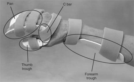
- Pan - supports the fingers and palm
- C bar - keeps the webspace of the thumb positioned in palmar abduction
- Thumb trough - cradles the thumb, at least ½ inch to support the thumb
- Forearm trough - supports the weight of the forearm
Diagram 2 - Fabrication Guide (Visual Instructions)
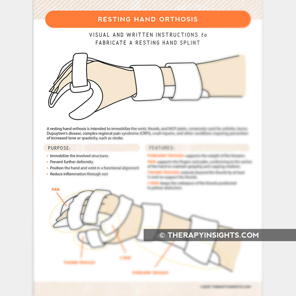
- Immobilize the involved structures
- Prevent further deformity
- Position the hand and wrist in a functional alignment
- Reduce inflammation through rest
Diagram 3 - Pattern Tracing Template
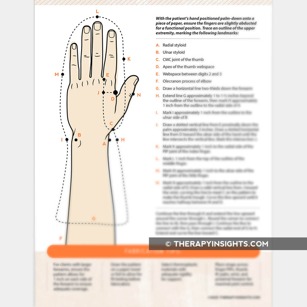
Key Positioning (Functional Resting Position)
| Joint | Position |
|---|---|
| Wrist | 20-30° extension |
| MCP joints | 45-70° flexion |
| IP joints | near full extension (0-20° flexion) |
| Thumb | palmar abduction, opposing fingers |
Diagram of dynamic wrist and orthosis
dynamic wrist hand orthosis splint diagram labeled
dynamic wrist extension orthosis radial nerve palsy splint components diagram
dynamic wrist hand finger orthosis outrigger components labeled diagram OT splinting
Diagram 1 - Dynamic Wrist Hand Orthosis (Radial Nerve Palsy / Wrist Drop Splint)
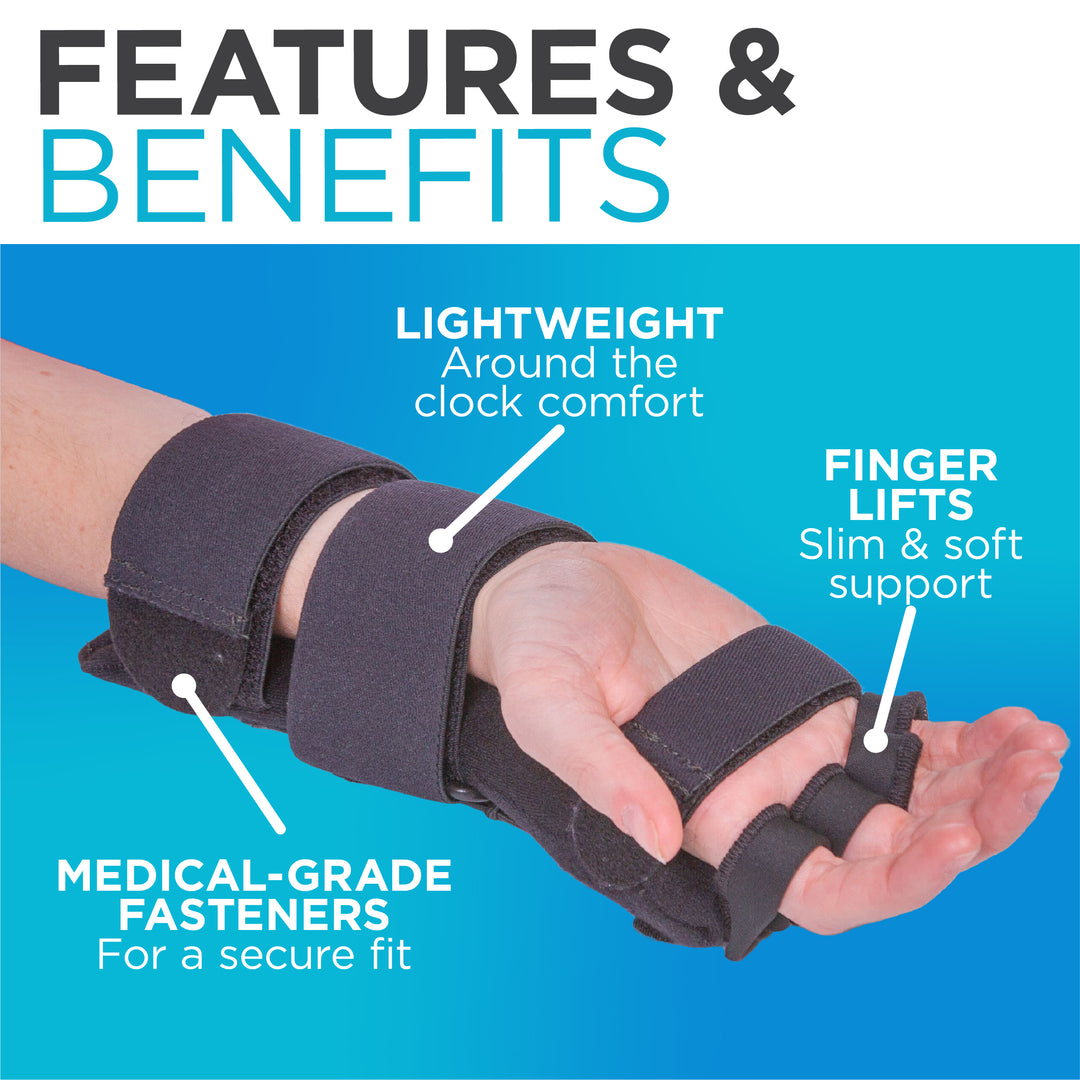
- Finger lifts - slim & soft support to lift fingers into extension
- Medical-grade fasteners - secure fit around forearm
- Lightweight forearm base - supports the wrist in extension
Diagram 2 - Outrigger-Based Dynamic Orthosis with Biomechanics

- Static outrigger - delivers high, constant force regardless of joint position (not ideal)
- Dynamic outrigger - delivers graduated, controlled force that follows the arc of flexion (preferred)
- F = Force of extensor pull (in Newtons)
- D = Arch of flexion
Diagram 3 - Phoenix Outrigger Fabrication (Dynamic Wrist-Hand Orthosis)
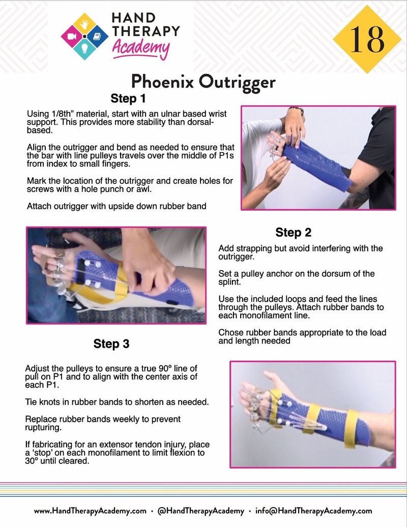
- Step 1 - Ulnar-based wrist support + outrigger bar aligned over P1 joints
- Step 2 - Pulley anchor on dorsum, monofilament lines, rubber band tension system
- Step 3 - Adjust to maintain true 90° line of pull; rubber bands replaced weekly
Key Components of a Dynamic Wrist Hand Orthosis
| Component | Function |
|---|---|
| Forearm trough/base | Static support; anchors the splint |
| Wrist support | Holds wrist in neutral or slight extension |
| Outrigger | Projects away from the splint to redirect the line of pull |
| Pulley/anchor | Redirects force to maintain 90° pull angle |
| Elastic/rubber bands | Provide dynamic traction force |
| Finger slings/loops | Cradle each finger; transmit the elastic force |
| Straps | Secure the splint to the forearm |
Common Indications
- Radial nerve palsy (wrist drop) - most common
- Extensor tendon repair - controlled mobilization
- Post-fracture stiffness - regain wrist ROM
- Burns - prevent contracture
- Stroke/CVA with wrist extensor weakness
Drawable diagram
A clean, clearly labeled medical/educational drawable diagram of a Dynamic Wrist Hand Orthosis (DWHO) shown from a lateral/side view and dorsal view. The diagram should show: a forearm trough base extending from mid-forearm to palm, a wrist support holding the wrist in slight extension, a dorsal outrigger (wire frame projecting upward and distally over the fingers), finger slings/loops on each finger connected by monofilament lines to the outrigger, rubber bands or elastic traction from the outrigger to the finger slings, and velcro straps securing the forearm base. Each component should be clearly labeled with arrows pointing to: Forearm Trough, Wrist Support, Outrigger, Pulley/Anchor, Elastic/Rubber Bands, Finger Slings, Velcro Straps. Style: clean black and white line art suitable for a medical textbook or student study guide, with neat labels and leader lines.
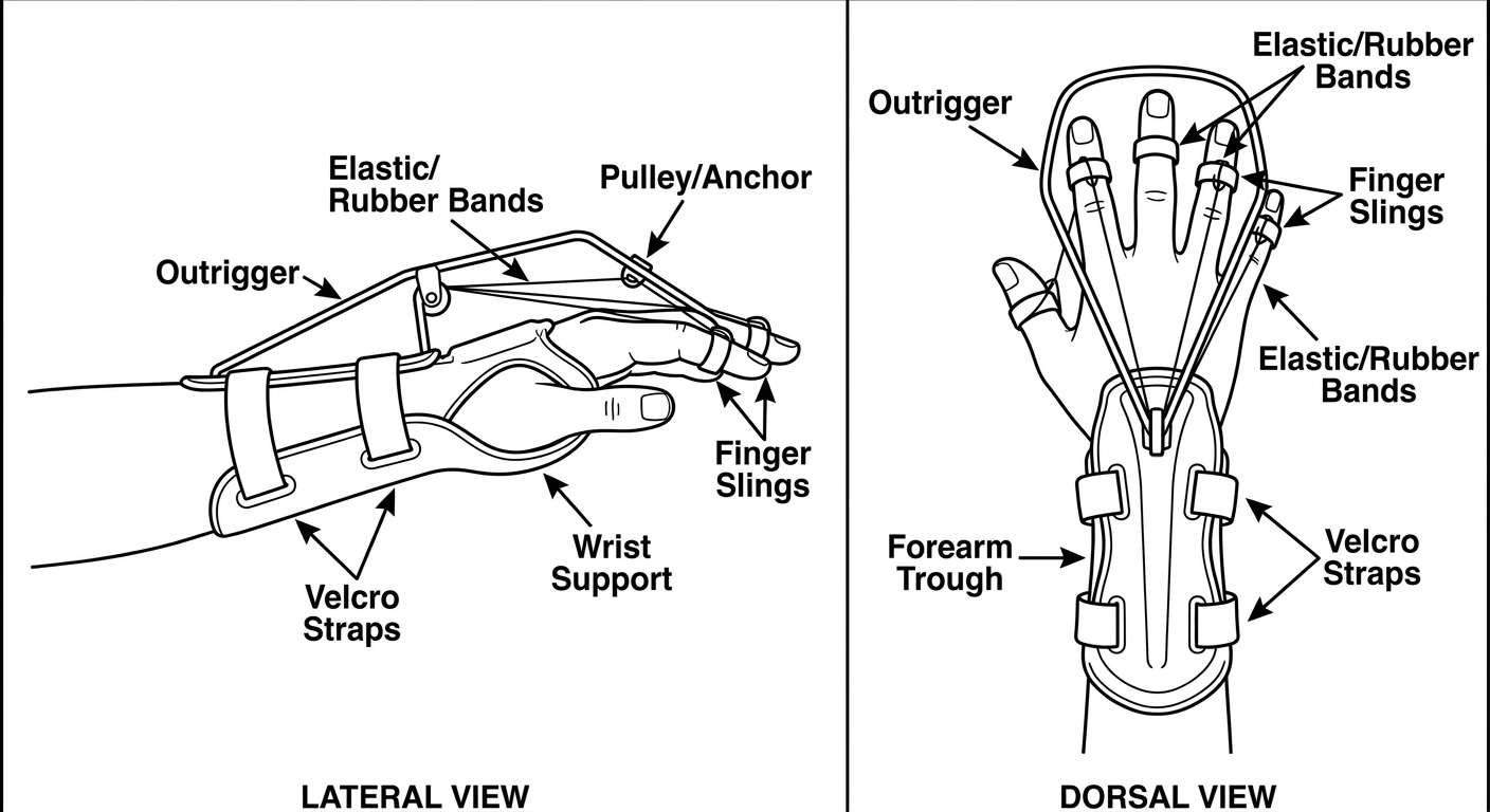
| Label | Component | Function |
|---|---|---|
| Forearm Trough | Static base extending mid-forearm to palm | Anchors the entire splint |
| Wrist Support | Holds wrist in ~20-30° extension | Prevents wrist drop |
| Outrigger | Wire/thermoplastic frame projecting dorsally over fingers | Directs line of pull at 90° to P1 |
| Pulley/Anchor | Fixed point on dorsum of splint | Redirects elastic force |
| Elastic/Rubber Bands | Connect outrigger to finger slings | Provide dynamic traction force |
| Finger Slings | Loop around proximal phalanx of each finger | Transmit force to extend fingers |
| Velcro Straps | 2-3 straps around forearm | Secure the splint to the limb |
Drawable diagram of dynamic finger extension ortosis
A clean, detailed medical educational drawable diagram of a Dynamic Finger Extension Orthosis shown from dorsal (back of hand) view. The diagram should clearly show: a hand-based thermoplastic base covering the dorsum of the hand and palm (metacarpal region), a low-profile outrigger wire arch projecting dorsally over all four fingers (index to little), individual finger slings made of soft loops placed around the proximal phalanx (P1) of each finger (index, middle, ring, little), monofilament lines running from each finger sling up to the outrigger, rubber bands or elastic traction attached from the monofilament to the outrigger providing extension force, velcro straps across the dorsum of the hand securing the base, and a thumb cutout showing the thumb is free. Each component must be clearly labeled with neat arrows: Hand-Based Thermoplastic Base, Low-Profile Outrigger, Finger Slings (on each finger), Monofilament Lines, Elastic/Rubber Band Traction, Velcro Strap, Thumb Cutout (free), 90° Angle of Pull arrow. Style: black and white clean line art, medical textbook illustration quality, suitable for student hand-drawing in OT or physiotherapy notes.
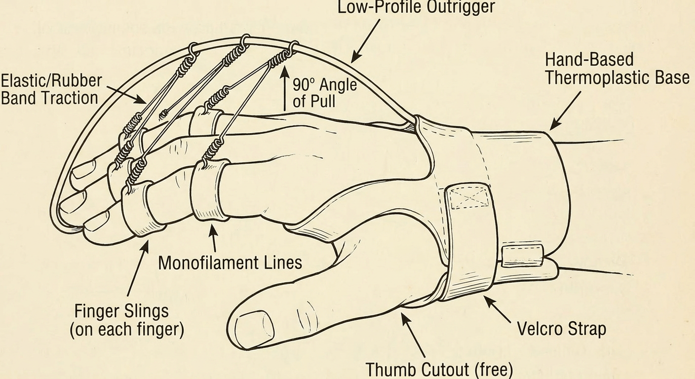
Key Components
| Component | Description |
|---|---|
| Hand-Based Thermoplastic Base | Covers the dorsum/palm at metacarpal level; anchors the splint |
| Low-Profile Outrigger | Wire or thermoplastic arch projecting dorsally over fingers |
| Finger Slings | Soft loops placed around the proximal phalanx (P1) of each finger |
| Monofilament Lines | Connect each finger sling to the outrigger |
| Elastic/Rubber Band Traction | Provides continuous dynamic extension force |
| Velcro Strap | Secures the base across the dorsum of the hand |
| Thumb Cutout | Thumb is left free for functional use |
| 90° Angle of Pull | The outrigger must be positioned so the pull is perpendicular to P1 |
Clinical Uses
- Extensor tendon repair - controlled early mobilization
- PIP/MCP joint stiffness - regain extension ROM
- Radial nerve palsy - hand-based version for finger extension only
- Post-fracture contracture - stretch flexion contractures
- Burns - prevent or correct extension lag
Key Principle
Diagram of dynamic finger flection orthosis draw
A clean, detailed medical educational drawable diagram of a Dynamic Finger Flexion Orthosis shown from the lateral (side) view and palmar (front) view of the hand. The diagram should clearly show: a forearm or hand-based thermoplastic base on the dorsal/volar surface, a palmar outrigger or pulley bar positioned at the palm level below the fingers, individual finger slings or nail hooks attached to the fingertips or middle phalanx of each finger (index, middle, ring, little), rubber bands or elastic cords running from each finger sling downward and palmarly toward the outrigger/pulley, pulling the fingers into flexion toward the palm, the MCP joints being pulled into flexion, a wrist strap and forearm strap securing the base, and a thumb left free. All components must be clearly labeled with neat arrows: Dorsal Forearm Base, Palmar Outrigger/Pulley Bar, Finger Nail Hook or Sling (on fingertip), Elastic Rubber Band pulling into flexion, Direction of Flexion Force (arrow toward palm), Velcro Wrist Strap, Thumb Free. Also show a small inset diagram of the 90 degree angle of pull at the proximal phalanx. Style: black and white clean line art, medical textbook quality, suitable for OT or physiotherapy student hand-drawing study notes.
400, message: Got more than 4194304 bytes when reading: b'data: {"candidates": [{"content": {"role": "model","parts": [{"inlineData": {"mimeType": "image/png"...'.
We encountered an error while processing your request. Please try again or reach out to us for help.
Diagram of dynamic finger flection or touches to draw
Clean black and white medical textbook line art diagram of a Dynamic Finger Flexion Orthosis, lateral side view. Shows: dorsal forearm thermoplastic base, palmar pulley bar at palm level, rubber bands pulling fingertips into flexion toward palm, nail hooks on fingertips, velcro straps on forearm. All parts labeled with arrows: Dorsal Base, Palmar Pulley Bar, Nail Hook, Rubber Band Traction, Flexion Force Direction, Velcro Strap. Simple clear style for student study notes.
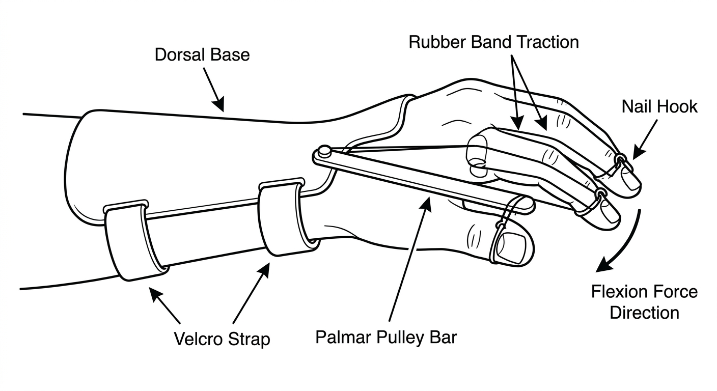
Key Components
| Component | Description |
|---|---|
| Dorsal Forearm/Hand Base | Thermoplastic base on the back of the hand/forearm - acts as the anchor |
| Palmar Pulley Bar | Positioned at palm level; redirects the elastic force toward the palm |
| Nail Hook / Finger Sling | Attached to fingertip or middle phalanx; connects finger to traction |
| Rubber Band / Elastic Traction | Pulls the finger toward the palm, creating dynamic flexion force |
| Flexion Force Direction | Force directed palmarly - toward the palm crease |
| Velcro Straps | Secure the dorsal base to the forearm/hand |
| Thumb | Usually left free |
How It Works
Clinical Indications
- Flexor tendon repair - early controlled mobilization (Kleinert protocol)
- PIP/MCP flexion contracture - regain lost flexion ROM
- Post-fracture stiffness - stretch extension contracture
- Dupuytren's contracture - post-op mobilization
- Burns - prevent extension contracture of fingers
Key Principle
Diagram of radial nerve pals is splint
Clean black and white medical textbook line art drawable diagram of a Radial Nerve Palsy Splint (Wrist Drop Splint / Cock-up splint with dynamic finger extension). Lateral and dorsal view of the hand and forearm. Shows: volar forearm thermoplastic base holding wrist in 30-40 degrees extension, dorsal outrigger wire arch projecting over fingers, individual finger slings on proximal phalanx of index middle ring and little fingers, rubber bands from finger slings to outrigger providing dynamic extension force, thumb post holding thumb in extension and abduction, velcro straps on forearm. Clearly label all parts with arrows: Volar Forearm Base, Wrist in 30-40 degree Extension, Dorsal Outrigger, Finger Slings, Rubber Band Traction, Thumb Post, Velcro Straps. Add small note: Indication - Radial Nerve Palsy / Wrist Drop. Simple clean style for OT physiotherapy student hand-drawing notes.
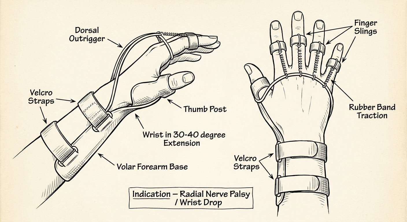
Key Components
| Component | Description |
|---|---|
| Volar Forearm Base | Thermoplastic base on the palm/forearm side - main anchor |
| Wrist in 30-40° Extension | Corrects the wrist drop deformity |
| Dorsal Outrigger | Wire/thermoplastic arch projecting over the fingers on the dorsal side |
| Finger Slings | Soft loops placed around proximal phalanx (P1) of all 4 fingers |
| Rubber Band Traction | Provides dynamic extension force to MCP joints |
| Thumb Post | Holds thumb in extension and radial abduction |
| Velcro Straps | 2-3 straps securing the forearm base |
Why These Features?
- Wrist extensors (ECRL, ECRB, ECU) - causes wrist drop
- Finger extensors (EDC, EIP, EDM) - cannot extend MCP joints
- Thumb extensors/abductor (EPL, EPB, APL) - thumb drops into palm
Types of Radial Nerve Palsy Splints
| Type | Use |
|---|---|
| Static cock-up splint | Simple wrist support only; no dynamic finger extension |
| Dynamic wrist-finger-thumb splint | Full substitution - wrist + finger + thumb extension |
| Tenodesis splint | Uses wrist movement to passively open/close hand |
Indication
Next radial gutter splint
Clean black and white medical textbook line art drawable diagram of a Radial Gutter Splint shown from dorsal and lateral views of the hand and forearm. The splint covers the radial (thumb) side of the forearm, wrist, and extends along the radial border supporting the index and middle fingers (2nd and 3rd digits) in a gutter. Show: a thermoplastic trough running along the radial aspect of the forearm down to the fingertips of index and middle fingers, wrist in neutral position, MCP and IP joints of index and middle fingers supported in slight flexion, thumb left free and visible, velcro straps securing the splint at forearm and hand level. Clearly label all parts with neat arrows: Radial Forearm Trough, Wrist in Neutral, Index Finger (2nd digit) supported, Middle Finger (3rd digit) supported, Thumb FREE (not included), Velcro Straps, MCP joints in slight flexion. Add small note box: Indications - 2nd/3rd metacarpal fractures, index/middle finger fractures, de Quervain tenosynovitis variant. Simple clean style suitable for OT physiotherapy student hand-drawing study notes.
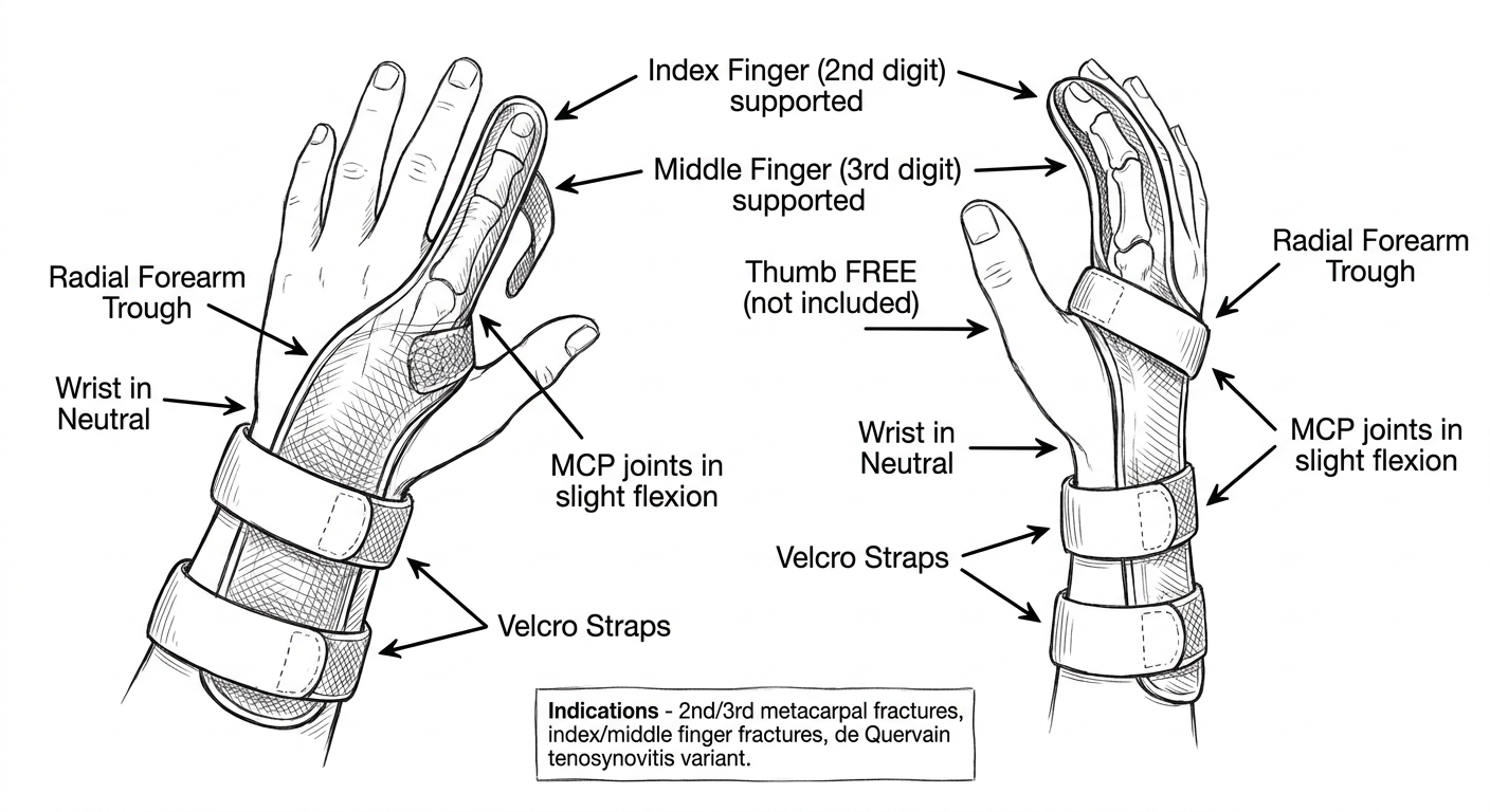
Key Components
| Component | Description |
|---|---|
| Radial Forearm Trough | Thermoplastic running along the radial (thumb) side of the forearm |
| Wrist in Neutral | Held at 0° - neutral position |
| Index Finger (2nd digit) | Supported in the gutter from MCP to fingertip |
| Middle Finger (3rd digit) | Supported in the gutter from MCP to fingertip |
| MCP joints | Held in slight flexion (~70-90°) |
| IP joints | Held in near full extension (0-10° flexion) |
| Thumb | Left completely FREE - not included in the splint |
| Velcro Straps | At forearm and hand level to secure the splint |
Positioning Summary
| Joint | Position |
|---|---|
| Wrist | Neutral (0°) |
| MCP joints (2nd & 3rd) | 70-90° flexion |
| PIP/DIP joints | 0-10° flexion (near extension) |
| Thumb | FREE |
Indications
- 2nd and 3rd metacarpal fractures (most common)
- Index and middle finger fractures (proximal/middle phalanx)
- 2nd/3rd MCP joint injuries
- Extensor tendon injuries to index or middle finger
- Post-operative immobilization of radial-side finger procedures
Key Points to Remember
- Covers the radial (lateral) border of the hand - index + middle fingers
- Thumb is always free (differentiates it from a thumb spica or hand-based thumb splint)
- The counterpart is the Ulnar Gutter Splint, which supports the ring and little fingers (4th & 5th digits) along the ulnar border
Next is mallet finger splint
Clean black and white medical textbook line art drawable diagram of a Mallet Finger Splint shown from lateral side view and dorsal view of a single finger. Show: a small thermoplastic or aluminium foam splint applied to the dorsal surface of the distal finger only, holding the DIP joint in full extension (0 degrees or slight hyperextension 5-10 degrees), PIP joint left completely free and mobile, fingertip visible, velcro strap or tape securing the splint at the middle and distal phalanx. Label all parts with neat arrows: Dorsal Splint on Distal Finger, DIP Joint in Full Extension (0 degrees), PIP Joint FREE and Mobile, Middle Phalanx, Distal Phalanx, Securing Strap or Tape. Add a small inset diagram showing the mallet deformity before splinting - finger drooping at DIP joint with extensor tendon rupture arrow. Add small note box: Indication - Mallet finger (extensor tendon rupture at DIP joint), Wear 6-8 weeks continuously. Simple clean style for OT physiotherapy student hand-drawing study notes.
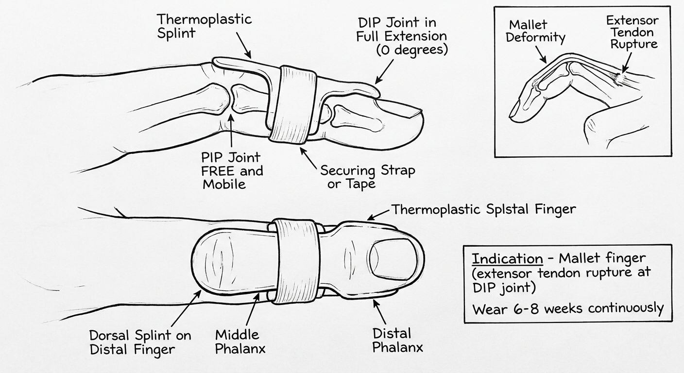
Key Components
| Component | Description |
|---|---|
| Dorsal Splint | Small thermoplastic or aluminium foam splint on dorsal surface of distal finger only |
| DIP Joint | Held in full extension (0°) or very slight hyperextension (5°) |
| PIP Joint | Left completely FREE and mobile - never included |
| Middle Phalanx | Proximal anchor of the splint |
| Distal Phalanx | Distal end supported by the splint |
| Securing Strap/Tape | Tape or velcro holds splint firmly to finger |
Positioning
| Joint | Position |
|---|---|
| DIP joint | 0° (full extension) or 5° hyperextension |
| PIP joint | Completely free - must be able to flex fully |
| MCP joint | Free |
Wearing Protocol
| Phase | Duration |
|---|---|
| Continuous wear (day + night, never remove) | 6-8 weeks |
| Weaning/night splint only | Additional 4-6 weeks |
| Total treatment | 10-12 weeks |
Critical rule: DIP joint must NEVER be allowed to flex even once during the initial 6-8 weeks - this restarts the healing clock from zero.
Indications
- Mallet finger - rupture of the terminal extensor tendon at the DIP joint
- Mallet fracture - bony avulsion of the dorsal base of the distal phalanx (if <1/3 of joint surface involved)
- Caused by: forced flexion of an extended finger (ball sports, jamming injury)
Types of Mallet Splints
| Type | Description |
|---|---|
| Stack splint | Most common prefabricated - volar + dorsal shell |
| Aluminium foam splint | Custom-molded, applied dorsally |
| Thermoplastic custom splint | Made by OT, better fit |
| Abouna splint | Dorsal application only |
Next is oval 8 finger splint
Clean black and white medical textbook line art drawable diagram of an Oval-8 Finger Splint shown in three configurations on a single finger lateral view. Configuration 1 top: Oval-8 worn to block hyperextension at PIP joint - figure-8 shaped metal ring splint with two oval loops, dorsal loop blocking PIP extension, label: Blocks PIP Hyperextension, Swan Neck Deformity. Configuration 2 middle: Oval-8 reversed to block flexion at PIP joint, label: Blocks PIP Flexion, Boutonniere Deformity. Configuration 3 bottom: Oval-8 worn at DIP joint to block hyperextension, label: DIP Mallet Finger / Trigger Finger. Each configuration shows the figure-8 shape clearly with two oval rings connected in the middle, one ring proximal to joint and one ring distal to joint, the joint in the center of the crossing point. Label all parts: Upper Oval Ring, Lower Oval Ring, Crossing Point at Joint, PIP Joint or DIP Joint. Add note box listing indications: Swan Neck deformity, Boutonniere deformity, Mallet finger, Trigger finger, Lateral band instability. Simple clean medical illustration style suitable for OT student hand-drawing notes.
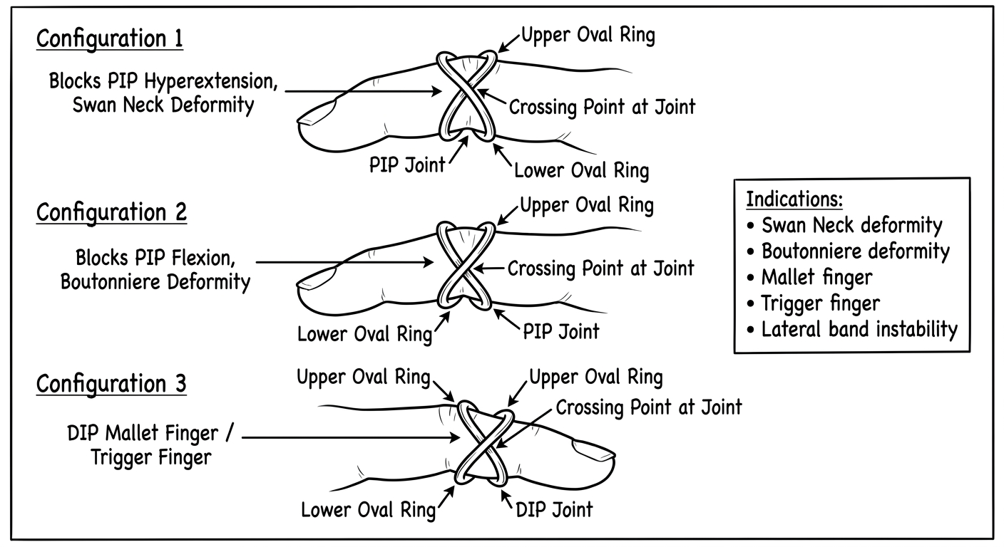
The Oval-8 Design
Three Configurations
| Configuration | Worn At | How | Blocks | Condition Treated |
|---|---|---|---|---|
| 1 - Dorsal block | PIP joint | Dorsal loop over PIP | Hyperextension | Swan Neck Deformity |
| 2 - Reversed (volar block) | PIP joint | Rotated 180° | Flexion / Boutonniere drop | Boutonniere Deformity |
| 3 - DIP application | DIP joint | Dorsal loop over DIP | DIP hyperextension or flexion drop | Mallet Finger / Trigger Finger |
Key Components
| Part | Description |
|---|---|
| Upper Oval Ring | Sits proximal to the target joint |
| Lower Oval Ring | Sits distal to the target joint |
| Crossing Point | Sits directly over the joint - acts as the block |
| Metal/Silver bar | The rigid crossing point prevents motion in one direction |
Indications
- Swan Neck Deformity - blocks PIP hyperextension (most common use)
- Boutonniere Deformity - blocks PIP flexion drop
- Mallet Finger - blocks DIP flexion
- Trigger Finger - blocks PIP snapping into flexion
- Lateral band instability - controls lateral deviation at PIP
- Rheumatoid Arthritis - joint instability management
Key Advantage
Boutonniere splint
Clean black and white medical textbook line art drawable diagram of a Boutonniere Deformity Splint shown in lateral side view of a single finger. Show two parts: Part 1 top - small inset diagram of Boutonniere Deformity showing PIP joint in flexion and DIP joint in hyperextension, with label: Boutonniere Deformity - PIP Flexion + DIP Hyperextension, central slip rupture arrow on dorsal PIP. Part 2 main diagram - the Boutonniere Splint (PIP extension splint) showing a small dorsal or three-point thermoplastic splint holding PIP joint in full extension 0 degrees, DIP joint left completely FREE and mobile, MCP joint free, proximal phalanx and middle phalanx as anchor points, securing straps or tape. Label all parts with neat arrows: Proximal Phalanx (anchor), PIP Joint held in FULL EXTENSION 0 degrees, Middle Phalanx (distal anchor), DIP Joint FREE and Mobile, Dorsal Thermoplastic Shell, Securing Strap. Add note box: Indication - Boutonniere Deformity (central slip injury), Wear continuously 6 weeks. Simple clean medical illustration style for OT physiotherapy student hand-drawing study notes.
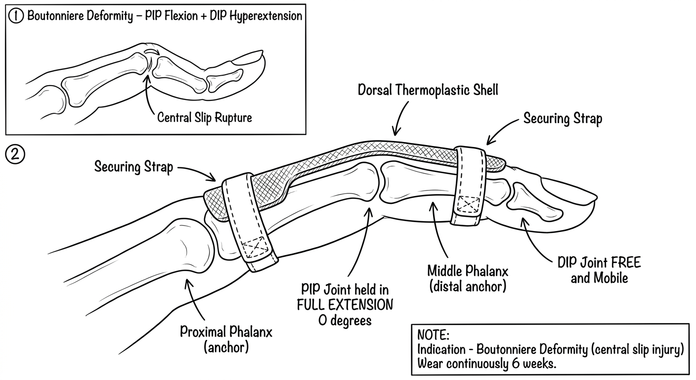
Understanding the Deformity First
| Feature | What Happens |
|---|---|
| Central slip | Ruptures at dorsal PIP joint |
| PIP joint | Drops into flexion (buttonholes through) |
| Lateral bands | Migrate volarly, pulling DIP into hyperextension |
| Appearance | PIP flexed + DIP hyperextended = classic Boutonniere |
The Boutonniere Splint - Key Components
| Component | Description |
|---|---|
| Dorsal Thermoplastic Shell | Applied to dorsal surface of PIP joint only |
| PIP Joint | Held in full extension (0°) - allows central slip to heal |
| Proximal Phalanx | Proximal anchor point |
| Middle Phalanx | Distal anchor point |
| DIP Joint | Left completely FREE - active DIP flexion encouraged |
| Securing Strap/Tape | Holds splint firmly against PIP |
Positioning
| Joint | Position |
|---|---|
| MCP joint | Free |
| PIP joint | 0° full extension (never allow flexion) |
| DIP joint | Free - active flexion exercises prescribed |
Wearing Protocol
| Phase | Duration |
|---|---|
| Continuous wear (day + night) | 6 weeks |
| Night splint + day exercises | 2-4 weeks more |
| Total | 8-10 weeks |
Key rule: Active DIP flexion exercises while wearing the splint are ESSENTIAL - this pulls the lateral bands dorsally back into correct position and helps restore extensor mechanism balance.
Comparison: Boutonniere vs Mallet Splint
| Feature | Boutonniere Splint | Mallet Splint |
|---|---|---|
| Joint splinted | PIP in extension | DIP in extension |
| Joint freed | DIP (must flex) | PIP (must be free) |
| Tendon injured | Central slip | Terminal extensor tendon |
| Deformity | PIP flexion + DIP hyperextension | DIP flexion drop |
Radial nerve palsy splint and thumb spoca orthosis
Clean black and white medical textbook line art drawable diagram of a Radial Nerve Palsy Splint (cock-up wrist drop splint with dynamic finger extension). Lateral and dorsal view. Shows: volar forearm thermoplastic base holding wrist in 30-40 degrees extension, dorsal outrigger wire arch over fingers, individual finger slings on proximal phalanx of all 4 fingers, rubber bands from finger slings to outrigger for dynamic extension, thumb post in extension and abduction, velcro straps on forearm. Label all parts: Volar Forearm Base, Wrist 30-40 degree Extension, Dorsal Outrigger, Finger Slings, Rubber Band Traction, Thumb Post, Velcro Straps. Indication note: Radial Nerve Palsy - Wrist Drop. Simple clean OT student study diagram style.
Clean black and white medical textbook line art drawable diagram of a Thumb Spica Orthosis (Short Opponens Splint) shown from dorsal and lateral view of the hand. Shows: forearm or wrist based thermoplastic trough extending along radial side of forearm and wrist, thumb trough or post immobilizing the thumb CMC and MCP joints in palmar abduction and opposition, IP joint of thumb left free and mobile, wrist held in slight extension 15-20 degrees, index and other fingers completely free, velcro straps at wrist and forearm. Label all parts with arrows: Forearm/Wrist Base, Thumb Trough (CMC + MCP immobilized), CMC Joint in Palmar Abduction, MCP Joint in slight flexion, Thumb IP Joint FREE, Wrist in 15-20 degrees Extension, Fingers FREE, Velcro Straps. Add indications note box: De Quervain Tenosynovitis, Thumb CMC Arthritis, Scaphoid Fracture, UCL Injury (Gamekeeper Thumb), Thumb Fractures. Simple clean medical illustration style for OT physiotherapy student hand-drawing study notes.
1. Radial Nerve Palsy Splint
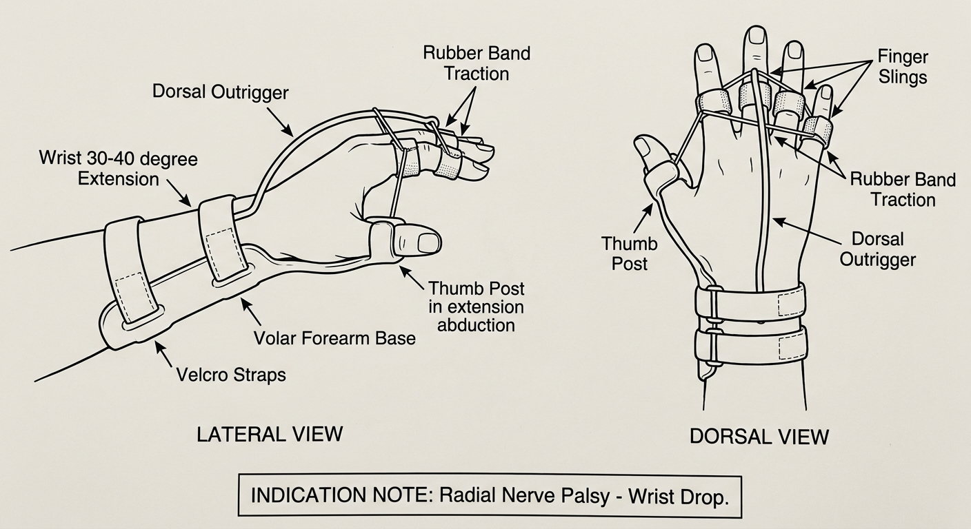
Key Components
| Component | Description |
|---|---|
| Volar Forearm Base | Thermoplastic anchor along the palm side of forearm |
| Wrist in 30-40° Extension | Corrects wrist drop deformity |
| Dorsal Outrigger | Wire arch over fingers directing extension force |
| Finger Slings | Loops at P1 of all 4 fingers |
| Rubber Band Traction | Dynamically extends MCP joints |
| Thumb Post | Holds thumb in extension + radial/palmar abduction |
| Velcro Straps | 2-3 straps securing forearm base |
2. Thumb Spica Orthosis
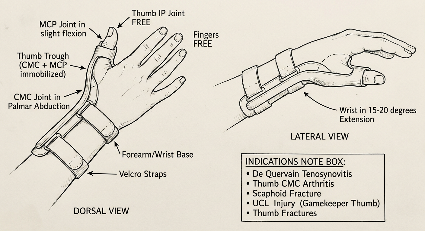
Key Components
| Component | Description |
|---|---|
| Forearm/Wrist Base | Radial-side thermoplastic trough from forearm to wrist |
| Thumb Trough | Immobilizes CMC + MCP joints of thumb |
| CMC Joint | In palmar abduction - functional rest position |
| MCP Joint | In slight flexion (~10-20°) |
| Thumb IP Joint | Left completely FREE |
| Wrist | 15-20° extension |
| Fingers | All FREE |
| Velcro Straps | At wrist and forearm |
Indications
| Condition | Reason |
|---|---|
| De Quervain Tenosynovitis | Rest APL + EPB tendons |
| Thumb CMC Arthritis | Offload CMC joint |
| Scaphoid Fracture | Immobilize wrist + CMC |
| UCL Injury (Gamekeeper's/Skier's Thumb) | Protect MCP ulnar collateral ligament |
| Thumb Metacarpal Fracture | Stabilize 1st metacarpal |
Quick Comparison
| Feature | Radial Nerve Palsy Splint | Thumb Spica |
|---|---|---|
| Type | Dynamic | Static |
| Wrist position | 30-40° extension | 15-20° extension |
| Fingers | Supported dynamically | All free |
| Thumb | Post (extension/abduction) | Trough (CMC+MCP immobilized) |
| Primary use | Nerve palsy | CMC/thumb injuries |
Short opponens and long opponius orthosis diagram
Clean black and white medical textbook line art drawable diagram of a Short Opponens Orthosis (hand-based thumb spica) shown from dorsal and lateral view. Shows: hand-based thermoplastic base covering only the palm and metacarpal area (does NOT extend onto the forearm), thumb trough holding thumb CMC and MCP joints in palmar abduction and opposition, thumb IP joint left free, all four fingers completely free, C-bar maintaining the first web space open, velcro strap across the dorsum of the hand. Label all parts with neat arrows: Hand-Based Thermoplastic (no forearm extension), C-Bar (maintains web space), Thumb Trough, CMC Joint in Palmar Abduction, MCP Joint supported, Thumb IP Joint FREE, Fingers ALL FREE, Velcro Strap. Add note box: Indications - Median nerve palsy, Thumb opposition weakness, Carpal tunnel syndrome, Mild CMC arthritis. Simple clean OT student study diagram style.
Clean black and white medical textbook line art drawable diagram of a Long Opponens Orthosis (forearm-based thumb spica) shown from dorsal and lateral view. Shows: long forearm-based thermoplastic trough extending from mid-forearm all the way to the hand, wrist held in 15-20 degrees extension, thumb trough holding CMC and MCP joints in palmar abduction and opposition, thumb IP joint left free, all four fingers completely free, C-bar maintaining first web space, two or three velcro straps on the forearm and one at the wrist. Label all parts with neat arrows: Long Forearm Trough (mid-forearm to hand), Wrist in 15-20 degree Extension, C-Bar (first web space), Thumb Trough, CMC Joint in Palmar Abduction, MCP Joint supported, Thumb IP Joint FREE, Fingers ALL FREE, Velcro Straps x3. Add note box: Indications - Rheumatoid arthritis, Scaphoid fracture, De Quervain tenosynovitis, Post-op thumb reconstruction, Severe CMC arthritis. Simple clean OT student study diagram style.
1. Short Opponens Orthosis (Hand-Based)
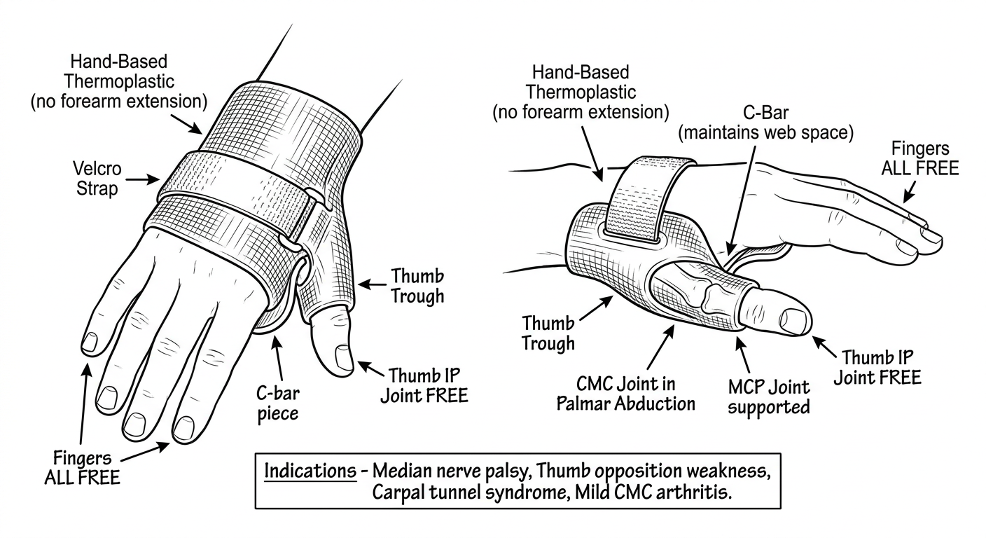
Key Components
| Component | Description |
|---|---|
| Hand-Based Thermoplastic | Covers palm only - does NOT extend onto forearm |
| C-Bar | Maintains the 1st web space open between thumb and index |
| Thumb Trough | Holds CMC + MCP in palmar abduction/opposition |
| CMC Joint | Palmar abduction - thumb pointing away from palm |
| MCP Joint | Slight flexion (~10°) |
| Thumb IP Joint | Completely FREE |
| Fingers | All FREE |
| Velcro Strap | One strap across dorsum of hand |
2. Long Opponens Orthosis (Forearm-Based)
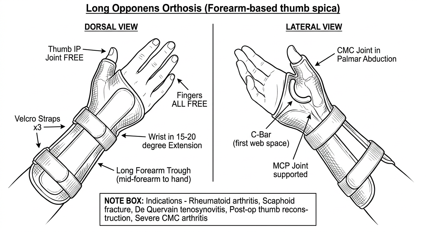
Key Components
| Component | Description |
|---|---|
| Long Forearm Trough | Extends from mid-forearm all the way to the hand |
| Wrist | Held in 15-20° extension |
| C-Bar | Maintains 1st web space open |
| Thumb Trough | Holds CMC + MCP in palmar abduction/opposition |
| Thumb IP Joint | Completely FREE |
| Fingers | All FREE |
| Velcro Straps x3 | At mid-forearm, distal forearm, and wrist |
Key Differences - Short vs Long Opponens
| Feature | Short Opponens | Long Opponens |
|---|---|---|
| Base | Hand only | Forearm + hand |
| Wrist | FREE - not included | Immobilized in 15-20° extension |
| Straps | 1 strap | 2-3 straps |
| Immobilization | CMC + MCP only | Wrist + CMC + MCP |
| Bulk/weight | Lighter, less bulky | More supportive, heavier |
| Best for | Functional use, mild conditions | Post-op, fractures, severe arthritis |
| Thumb IP | Free (both) | Free (both) |
| Fingers | Free (both) | Free (both) |
The C-Bar - Why It Matters
- Maintains the 1st web space in abduction
- Prevents thumb adduction contracture
- Is present in both short and long opponens orthoses
- Named for its C-shape appearance when viewed from above
Thumb abduction orthosis and thumb post orthosis and finger gutter splint and ulnar gutter splint
Clean black and white medical textbook line art drawable diagram of a Thumb Abduction Orthosis shown dorsal and lateral view. Hand-based thermoplastic splint with a wide C-bar and web spacer holding the thumb in maximum radial and palmar abduction away from the palm, thumb MCP and IP joints free, fingers free, velcro strap on hand dorsum. Label: Wide C-Bar Web Spacer, Thumb in Maximum Abduction, MCP Joint Free, IP Joint Free, Fingers Free, Velcro Strap. Indications note: Adduction contracture prevention, Burn injury web space, Median nerve palsy. Simple clean OT student study diagram.
Clean black and white medical textbook line art drawable diagram of a Thumb Post Orthosis shown dorsal and lateral view. Small hand-based thermoplastic post or platform supporting only the thumb metacarpal and MCP joint in extension and abduction, thumb IP joint free, all fingers free, small velcro strap. Label: Thumb Post (metacarpal support), MCP Joint in Extension, CMC in Abduction, Thumb IP Joint FREE, Fingers FREE, Velcro Strap. Indications note: Thumb MCP instability, UCL repair, Gamekeeper thumb, Post-surgical stabilization. Simple clean OT student study diagram.
Clean black and white medical textbook line art drawable diagram of a Finger Gutter Splint shown lateral and dorsal view on a single finger. Aluminum foam or thermoplastic trough shaped like a U-gutter wrapping around one finger from tip to proximal phalanx, holding MCP PIP and DIP joints in slight flexion functional position, secured with tape or velcro. Label: Finger Gutter Trough (U-shaped), Proximal Phalanx, Middle Phalanx, Distal Phalanx, MCP Joint in slight flexion, PIP Joint supported, DIP Joint supported, Securing Tape or Velcro. Indications note: Single finger fracture, Soft tissue injury, Post-dislocation immobilization. Simple clean OT student study diagram.
Clean black and white medical textbook line art drawable diagram of an Ulnar Gutter Splint shown dorsal and lateral view of the hand and forearm. Thermoplastic trough running along the ulnar (little finger) side of the forearm and hand, supporting ring finger (4th digit) and little finger (5th digit) from proximal phalanx to fingertip in a gutter, wrist in neutral position, MCP joints in 70-90 degrees flexion, IP joints in near full extension, thumb and index and middle fingers completely free, velcro straps. Label: Ulnar Forearm Trough, Wrist Neutral, Ring Finger 4th digit in gutter, Little Finger 5th digit in gutter, MCP Joints 70-90 degree flexion, IP Joints near extension, Thumb + Index + Middle FREE, Velcro Straps. Indications: 4th and 5th metacarpal fractures, Boxer fracture, Ring and little finger injuries. Simple clean OT student study diagram.
429 Too Many Requests. {'message': '{\n "error": {\n "code": 429,\n "message": "Resource exhausted. Please try again later. Please refer to https://cloud.google.com/vertex-ai/generative-ai/docs/error-code-429 for more details.",\n "status": "RESOURCE_EXHAUSTED"\n }\n}\n', 'status': 'Too Many Requests'}
We encountered an error while processing your request. Please try again or reach out to us for help.
Continue with thumb. Abduction orthosis and thumb post orthosis
Clean black and white medical textbook line art drawable diagram of a Thumb Abduction Orthosis shown dorsal and lateral view. Hand-based thermoplastic splint with a wide C-bar and web spacer holding the thumb in maximum radial and palmar abduction away from the palm, thumb MCP and IP joints free, fingers free, velcro strap on hand dorsum. Label with arrows: Wide C-Bar Web Spacer, Thumb in Maximum Abduction, MCP Joint Free, IP Joint Free, Fingers Free, Velcro Strap. Indications note box: Adduction contracture prevention, Burn injury web space, Median nerve palsy. Simple clean OT student study diagram style.
Clean black and white medical textbook line art drawable diagram of a Thumb Post Orthosis shown dorsal and lateral view of the hand. Small hand-based thermoplastic post or platform supporting only the thumb metacarpal and MCP joint in extension and abduction, thumb IP joint completely free, all four fingers free, small velcro strap across dorsum of hand. Label with arrows: Thumb Metacarpal Post, MCP Joint in Extension, CMC in Abduction, Thumb IP Joint FREE, Fingers FREE, Velcro Strap. Indications note box: Thumb MCP instability, UCL repair Gamekeeper thumb, Post-surgical thumb stabilization. Simple clean OT physiotherapy student study diagram style.
1. Thumb Abduction Orthosis
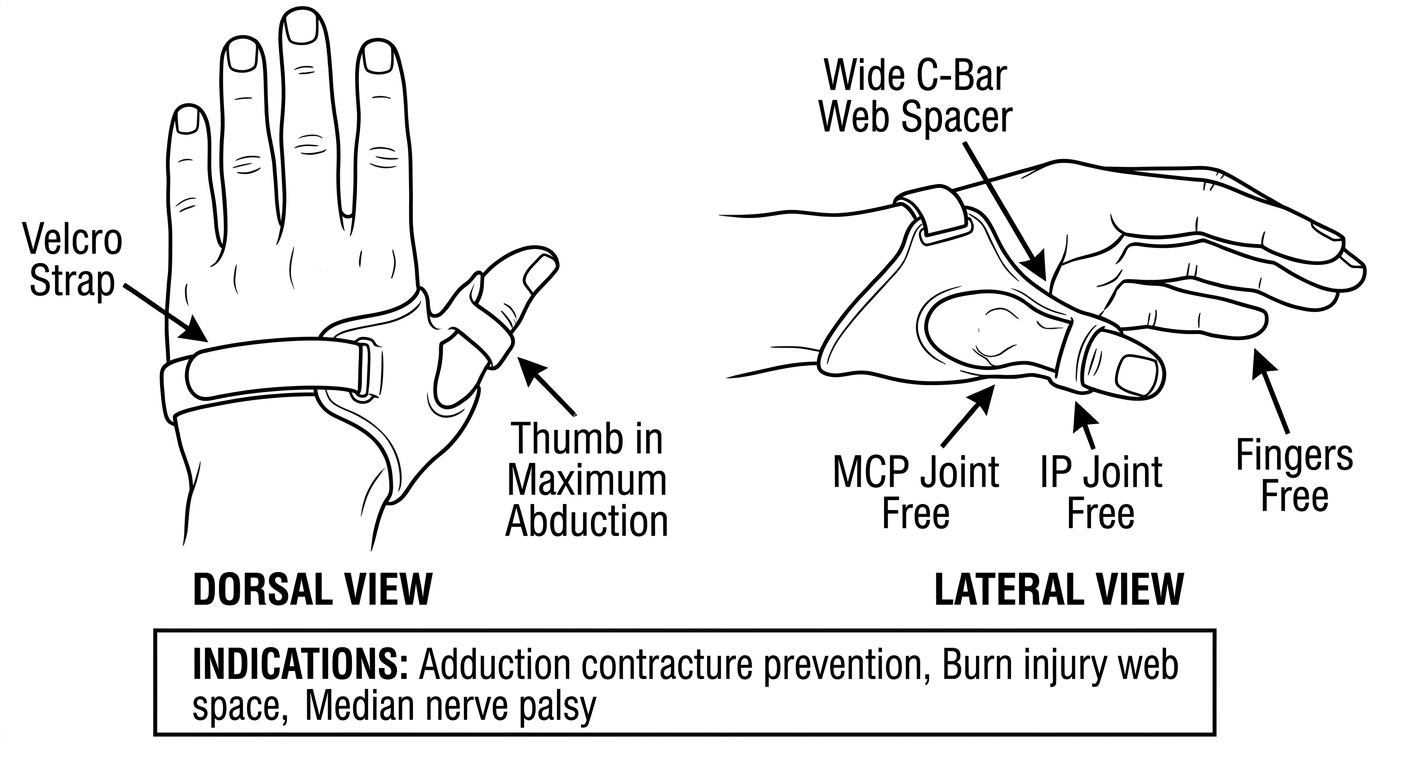
Key Components
| Component | Description |
|---|---|
| Wide C-Bar / Web Spacer | Broad thermoplastic piece filling and stretching the 1st web space |
| Thumb in Maximum Abduction | Held away from the palm in full radial + palmar abduction |
| MCP Joint | Free - not immobilized |
| IP Joint | Completely free |
| Fingers | All four fingers free |
| Velcro Strap | Secures across dorsum of hand |
Indications
- Adduction contracture - prevents or corrects thumb web space tightness
- Burn injury - maintains 1st web space during healing
- Median nerve palsy - prevents adduction contracture when opposition lost
- Post-surgical web space release
2. Thumb Post Orthosis
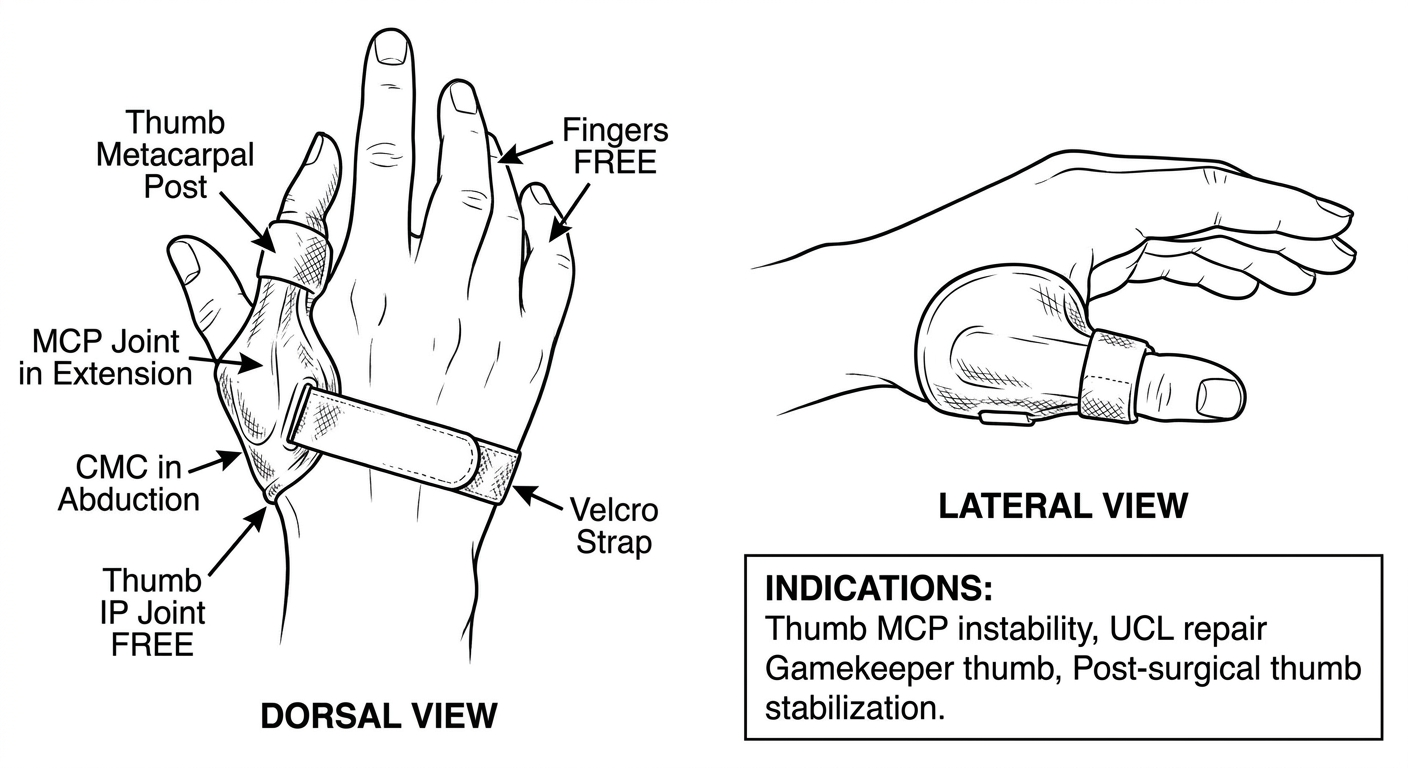
Key Components
| Component | Description |
|---|---|
| Thumb Metacarpal Post | Small thermoplastic platform supporting the 1st metacarpal |
| CMC Joint | Held in abduction |
| MCP Joint | Supported in extension |
| Thumb IP Joint | Completely FREE |
| Fingers | All FREE |
| Velcro Strap | Single strap across dorsum of hand |
Indications
- UCL injury (Gamekeeper's / Skier's Thumb) - protects MCP ulnar collateral ligament
- Thumb MCP instability
- Post-surgical thumb stabilization
- Thumb MCP arthritis
Quick Comparison
| Feature | Thumb Abduction Orthosis | Thumb Post Orthosis |
|---|---|---|
| Primary goal | Maintain/stretch web space | Stabilize MCP joint |
| Key component | Wide C-bar web spacer | Metacarpal post/platform |
| CMC position | Maximum abduction | Abduction |
| MCP | Free | Supported/stabilized |
| IP Joint | Free | Free |
| Fingers | Free | Free |
| Main indication | Burn / contracture / median nerve palsy | UCL injury / MCP instability |
Finger gutter splint and ulnar gutter splint
Clean black and white medical textbook line art drawable diagram of a Finger Gutter Splint shown in lateral and dorsal view on a single finger. A U-shaped aluminum foam or thermoplastic trough wrapping around one finger from proximal phalanx to fingertip, holding MCP PIP and DIP joints in slight functional flexion position, secured with circumferential tape or velcro straps at two points. Label all parts with neat arrows: U-Shaped Gutter Trough, Proximal Phalanx, Middle Phalanx, Distal Phalanx, MCP Joint slight flexion, PIP Joint supported, DIP Joint supported, Securing Tape or Velcro x2. Add indications note box: Single finger fracture, Soft tissue injury, Post-dislocation immobilization, Phalangeal fracture. Simple clean OT physiotherapy student hand-drawing study notes style.
Clean black and white medical textbook line art drawable diagram of an Ulnar Gutter Splint shown in dorsal and lateral view of the hand and forearm. Thermoplastic trough running along the ulnar side of the forearm and hand, forming a gutter that supports ring finger (4th digit) and little finger (5th digit) from proximal phalanx to fingertips, wrist held in neutral 0 degrees, MCP joints in 70-90 degrees flexion, IP joints in near full extension 0-10 degrees, thumb and index and middle fingers completely free, two velcro straps on forearm and one at hand. Label all parts with neat arrows: Ulnar Forearm Trough, Wrist in Neutral, Ring Finger 4th digit, Little Finger 5th digit, MCP Joints 70-90 degree flexion, IP Joints near extension, Thumb plus Index plus Middle FREE, Velcro Straps. Indications note box: 4th and 5th metacarpal fractures, Boxer fracture 5th metacarpal, Ring and little finger phalangeal fractures, Ulnar-side hand injuries. Simple clean OT physiotherapy student hand-drawing study notes style.
1. Finger Gutter Splint
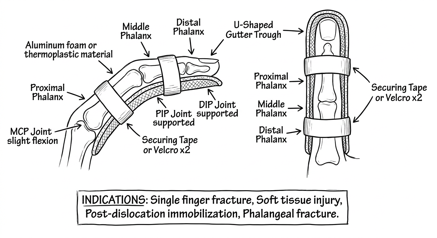
Key Components
| Component | Description |
|---|---|
| U-Shaped Gutter Trough | Aluminium foam or thermoplastic, wraps around one finger |
| Proximal Phalanx | Proximal anchor of the gutter |
| Middle Phalanx | Supported in the trough |
| Distal Phalanx | Distal end supported to fingertip |
| MCP Joint | Slight flexion (~20-30°) |
| PIP Joint | Supported in slight flexion |
| DIP Joint | Supported in slight flexion |
| Securing Tape / Velcro x2 | At proximal and distal ends of the gutter |
Positioning
| Joint | Position |
|---|---|
| MCP | 20-30° flexion |
| PIP | 10-20° flexion |
| DIP | 10° flexion |
Indications
- Single finger phalangeal fracture
- Post-dislocation (PIP/DIP) immobilization
- Soft tissue finger injuries
- Buddy-taping base for unstable injuries
2. Ulnar Gutter Splint
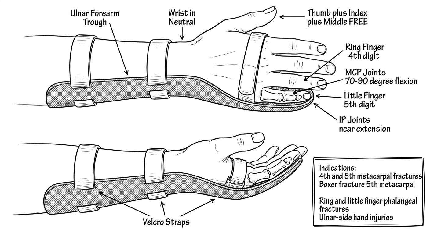
Key Components
| Component | Description |
|---|---|
| Ulnar Forearm Trough | Runs along the ulnar (little finger) side of forearm |
| Wrist | Held in neutral (0°) |
| Ring Finger (4th digit) | Fully supported in gutter |
| Little Finger (5th digit) | Fully supported in gutter |
| MCP Joints | 70-90° flexion (intrinsic plus position) |
| IP Joints | Near full extension (0-10°) |
| Thumb + Index + Middle | All completely FREE |
| Velcro Straps | 2 on forearm + 1 at hand |
Positioning
| Joint | Position |
|---|---|
| Wrist | 0° neutral |
| MCP (4th & 5th) | 70-90° flexion |
| PIP/DIP (4th & 5th) | 0-10° (near extension) |
Indications
- Boxer's fracture (5th metacarpal neck fracture) - most common
- 4th and 5th metacarpal fractures
- Ring and little finger phalangeal fractures
- Ulnar-side hand injuries
- 4th/5th MCP joint dislocations
Radial vs Ulnar Gutter - Quick Comparison
| Feature | Radial Gutter | Ulnar Gutter |
|---|---|---|
| Side | Radial (thumb side) | Ulnar (little finger side) |
| Fingers included | Index (2nd) + Middle (3rd) | Ring (4th) + Little (5th) |
| Thumb | Free | Free |
| Common use | 2nd/3rd metacarpal fractures | Boxer's fracture (5th metacarpal) |
| Wrist position | Neutral | Neutral |
| MCP position | 70-90° flexion | 70-90° flexion |
Swan neck splint and finger extension assist orthosis
Clean black and white medical textbook line art drawable diagram of a Swan Neck Deformity Splint shown in lateral side view of a single finger. Show two parts: top inset - swan neck deformity diagram showing PIP joint in hyperextension and DIP joint in flexion, labeled Swan Neck Deformity - PIP Hyperextension plus DIP Flexion. Main diagram below - three-point pressure splint or figure-8 ring splint (like Oval-8 or silver ring splint) applied at PIP joint blocking hyperextension while allowing flexion, dorsal pressure pad over PIP joint, two volar support points proximal and distal to PIP. Label all parts with neat arrows: Three-Point Pressure System, Dorsal Pad over PIP joint (blocks hyperextension), Volar Support Proximal to PIP, Volar Support Distal to PIP, PIP Joint allowed to FLEX but blocked from hyperextension, DIP Joint Free, MCP Joint Free. Add indications note box: Rheumatoid Arthritis, Hypermobility syndrome, Post-traumatic swan neck. Simple clean OT physiotherapy student hand-drawing study notes style.
Clean black and white medical textbook line art drawable diagram of a Finger Extension Assist Orthosis shown in lateral side view and dorsal view of a single finger or whole hand. Shows a hand-based or finger-based dynamic splint with a small spring coil or elastic component on the dorsal side of the finger at PIP joint level, providing upward extension assist force to lift the finger into extension, while allowing active flexion against the spring resistance. The base is secured to the proximal phalanx or hand dorsum, the spring or elastic attaches to the middle phalanx. Label all parts with neat arrows: Finger Base (proximal phalanx anchor), Spring Coil or Elastic Component, Extension Assist Force arrow pointing upward, Middle Phalanx attachment, PIP Joint assisted into extension, Active Flexion still possible against resistance, Securing Strap. Add indications note box: PIP extension lag, Extensor tendon weakness, Ulnar nerve palsy, Post-operative PIP stiffness, Boutonniere late stage. Simple clean OT physiotherapy student hand-drawing study notes style.
1. Swan Neck Deformity Splint
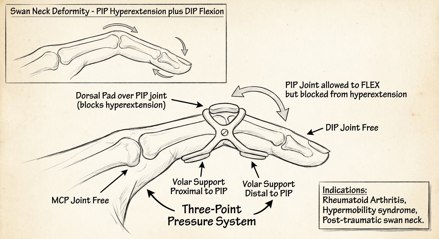
Understanding the Deformity
| Feature | What Happens |
|---|---|
| PIP joint | Hyperextends (snaps back) |
| DIP joint | Flexes (drops down) |
| Cause | Volar plate laxity, intrinsic tightness, rheumatoid arthritis |
| Appearance | Finger looks like a swan's neck - curved middle, drooping tip |
The Three-Point Pressure System
| Pressure Point | Location | Direction |
|---|---|---|
| Point 1 | Dorsal surface of PIP joint | Pushes DOWN - blocks hyperextension |
| Point 2 | Volar surface proximal to PIP | Pushes UP |
| Point 3 | Volar surface distal to PIP | Pushes UP |
The splint blocks PIP hyperextension but still allows PIP flexion - this is the key difference from a full immobilization splint.
Key Components
| Component | Description |
|---|---|
| Dorsal Pad over PIP | Blocks hyperextension - the main working part |
| Volar Proximal Support | Counter-pressure point on P1 |
| Volar Distal Support | Counter-pressure point on P2 |
| PIP Joint | Allows flexion, blocks hyperextension only |
| DIP Joint | Free |
| MCP Joint | Free |
Types of Swan Neck Splints
| Type | Example |
|---|---|
| Figure-8 ring splint | Oval-8, Silver ring splint |
| Three-point thermoplastic | Custom OT-fabricated |
| Finger ring splint | Metal prefabricated |
Indications
- Rheumatoid arthritis (most common)
- Hypermobility syndrome (Ehlers-Danlos)
- Post-traumatic PIP volar plate laxity
2. Finger Extension Assist Orthosis
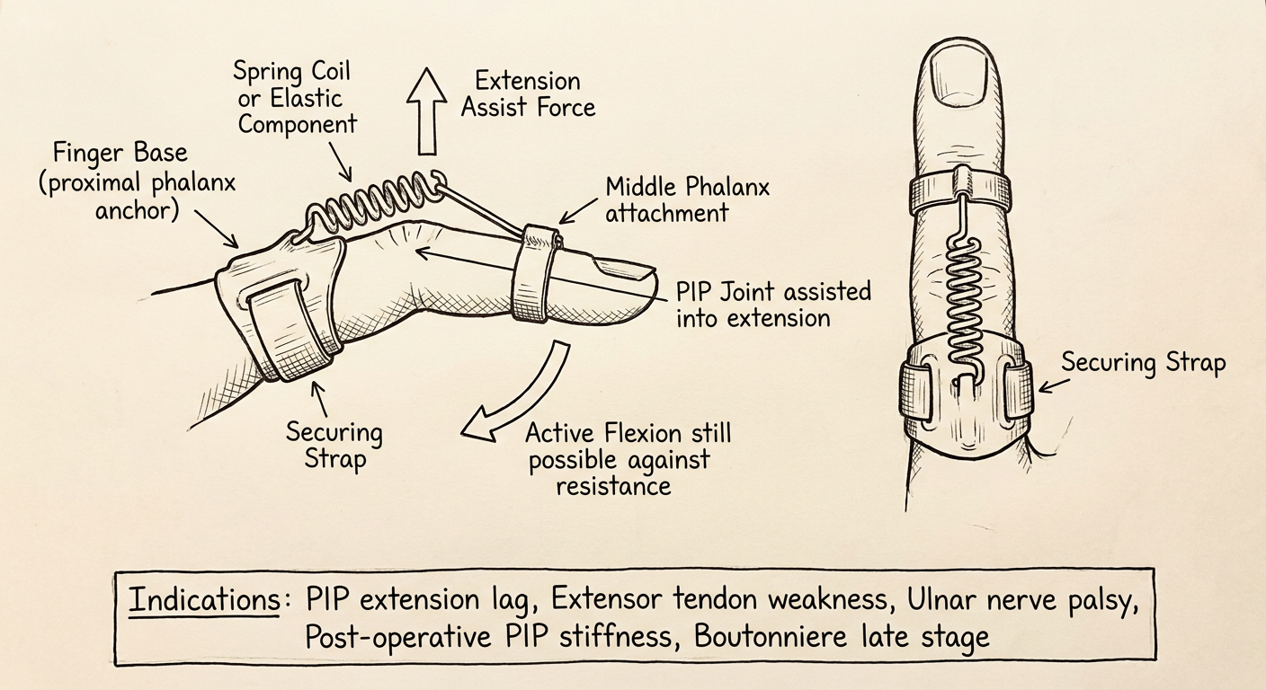
Key Components
| Component | Description |
|---|---|
| Finger Base / Anchor | Secured to proximal phalanx or hand dorsum |
| Spring Coil / Elastic | Provides continuous upward extension assist force |
| Extension Assist Force | Lifts finger into extension dynamically |
| Middle Phalanx Attachment | Where the spring connects distally |
| PIP Joint | Assisted into extension by the spring |
| Active Flexion | Still possible - patient works against the spring |
| Securing Strap | Holds base firmly to finger/hand |
How It Works
- The spring or elastic component provides a constant gentle extension force at the PIP joint
- The patient can still actively flex the finger against the resistance (exercise component)
- When the patient relaxes, the spring returns the finger to extension
- This creates a dynamic assist rather than full immobilization
Indications
- PIP extension lag - finger cannot fully extend actively
- Extensor tendon weakness - partial recovery phase
- Ulnar nerve palsy - intrinsic minus hand, clawing
- Post-operative PIP stiffness - late-stage rehab
- Boutonniere deformity - late stage remodeling phase
- Post-fracture extension deficit
Comparison: Swan Neck vs Boutonniere vs Extension Assist
| Feature | Swan Neck Splint | Boutonniere Splint | Extension Assist Orthosis |
|---|---|---|---|
| PIP position | Free to flex, blocks hyperextension | Held in full extension (0°) | Assisted into extension dynamically |
| DIP | Free | Free (must flex) | Free |
| Type | Static blocking | Static immobilization | Dynamic assist |
| Main deformity | PIP hyperextension | PIP flexion | PIP extension lag/weakness |
| Mechanism | 3-point pressure | Full immobilization | Spring/elastic traction |
| Active motion | Allowed (flexion) | Not allowed at PIP | Encouraged (against resistance) |
Mcp blocking orthosis anti claw splint and dynamic mcp flexion orthosis diagram
Clean black and white medical textbook line art drawable diagram of an MCP Blocking Orthosis also called Anti-Claw Splint shown in lateral side view and dorsal view of the hand. Shows: small hand-based thermoplastic splint with a volar MCP block bar positioned across the volar aspect of all four MCP joints preventing MCP hyperextension, MCP joints held at 70-90 degrees flexion, PIP and DIP joints completely free to flex and extend, thumb free, velcro strap on dorsum of hand. Include small inset showing claw deformity before splinting - MCP hyperextension with PIP DIP flexion in ring and little fingers, labeled Ulnar Claw Deformity. Label all parts with neat arrows: Volar MCP Block Bar, MCP Joints blocked at 70-90 degree flexion, PIP Joint FREE, DIP Joint FREE, Thumb FREE, Velcro Strap, Intrinsic Plus Position. Add indications note box: Ulnar nerve palsy claw hand, Combined median ulnar nerve palsy, Intrinsic minus hand. Simple clean OT physiotherapy student hand-drawing study notes style.
Clean black and white medical textbook line art drawable diagram of a Dynamic MCP Flexion Orthosis shown in lateral side view and dorsal view of the hand. Shows: forearm or hand based thermoplastic base, a volar or palmar outrigger bar or pulley at palm level, individual finger slings placed on the proximal phalanx of all four fingers, rubber bands or elastic cords running from each finger sling down toward the palmar pulley bar pulling the MCP joints into flexion, PIP and DIP joints free, thumb free, velcro straps on forearm. Label all parts with neat arrows: Forearm or Hand Base, Palmar Outrigger or Pulley Bar, Finger Slings on Proximal Phalanx, Rubber Band Elastic pulling MCP into Flexion, Direction of Flexion Force arrow, PIP and DIP Joints FREE, Thumb FREE, Velcro Straps. Add indications note box: MCP joint stiffness in extension, Post-fracture MCP extension contracture, Intrinsic tightness, Post-surgical MCP stiffness. Simple clean OT physiotherapy student hand-drawing study notes style.
400, message: Got more than 4194304 bytes when reading: b'data: {"candidates": [{"content": {"role": "model","parts": [{"inlineData": {"mimeType": "image/png"...'.
We encountered an error while processing your request. Please try again or reach out to us for help.
Mcp blocking orthosis
Black and white medical textbook line art diagram of MCP Blocking Orthosis anti-claw splint, lateral and dorsal view. Hand-based thermoplastic splint with volar MCP block bar across all four MCP joints preventing hyperextension, MCP joints at 70-90 degrees flexion, PIP and DIP joints free, thumb free, dorsal velcro strap. Small inset showing ulnar claw deformity. Labels: Volar MCP Block Bar, MCP 70-90 degrees flexion, PIP FREE, DIP FREE, Thumb FREE, Velcro Strap. Indications: Ulnar nerve palsy, Claw hand. Clean simple student study style.
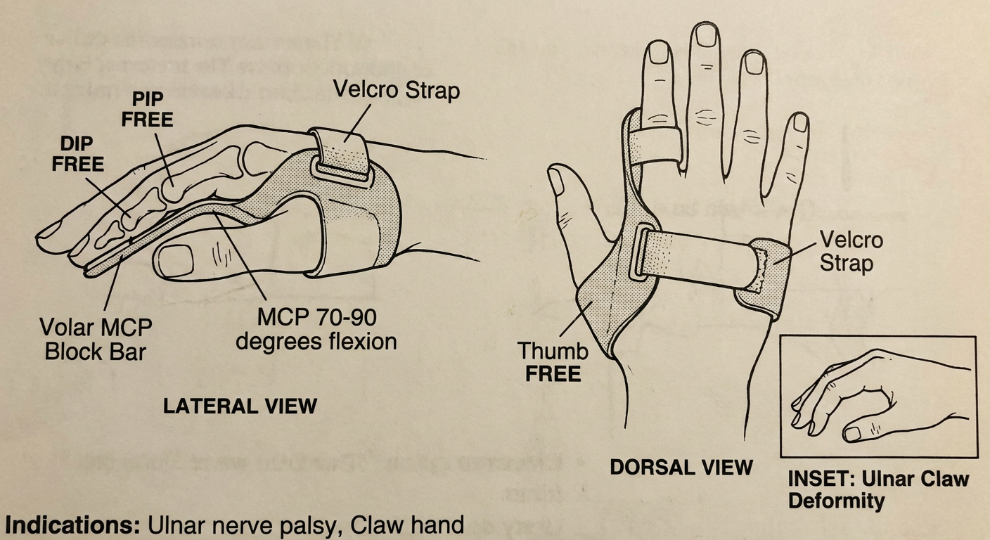
Understanding the Claw Deformity First
| Feature | What Happens |
|---|---|
| MCP joints | Hyperextend (pull back) |
| PIP + DIP joints | Flex (curl down) |
| Cause | Intrinsic muscle paralysis (ulnar/median nerve) |
| Appearance | Fingers clawed - MCP up, IP joints curled |
| Nerves affected | Ulnar nerve (ring + little fingers) / Combined median + ulnar (all 4 fingers) |
Key Components
| Component | Description |
|---|---|
| Volar MCP Block Bar | Thermoplastic bar across volar aspect of all 4 MCP joints |
| MCP Joints | Blocked at 70-90° flexion (intrinsic plus position) |
| PIP Joints | Completely FREE to flex and extend |
| DIP Joints | Completely FREE |
| Thumb | FREE - not included |
| Velcro Strap | Dorsal strap holding the block in place |
How It Works
Positioning
| Joint | Position |
|---|---|
| MCP (all 4 fingers) | 70-90° flexion - blocked here |
| PIP joints | Free - full active range |
| DIP joints | Free - full active range |
Indications
- Ulnar nerve palsy - ring + little finger clawing (most common)
- Combined median + ulnar nerve palsy - all 4 finger clawing
- Low ulnar nerve injury - below elbow
- Leprosy - intrinsic muscle paralysis
- Post-surgical nerve repair - while awaiting reinnervation
Anti-Claw vs Knuckle Bender
| Feature | Anti-Claw (MCP Block) | Knuckle Bender |
|---|---|---|
| Action | Blocks MCP hyperextension | Forces MCP into flexion |
| Type | Static blocking | Dynamic flexion assist |
| MCP | Held at 70-90° | Pulled into flexion |
| Goal | Restore functional use | Increase MCP flexion ROM |
Anti claw splint and dynamic mcp flexion
Black and white medical line art diagram of Anti-Claw Splint lateral view. Hand-based thermoplastic with volar MCP block bar preventing MCP hyperextension, MCPs held at 70-90 degrees flexion, PIP DIP free, thumb free, dorsal strap. Labels: Volar MCP Block Bar, MCP 70-90deg flexion, PIP free, DIP free, Velcro Strap. Ulnar nerve palsy indication. Clean student OT notes style.
Black and white medical line art diagram of Dynamic MCP Flexion Orthosis lateral view. Forearm base, palmar outrigger pulley bar at palm, finger slings on proximal phalanx of all four fingers, rubber bands pulling MCP joints into flexion toward palm, PIP DIP free, thumb free, velcro straps. Labels: Forearm Base, Palmar Pulley Bar, Finger Slings on P1, Rubber Band Traction, Flexion Force arrow, PIP DIP Free. Indications: MCP extension contracture, post-fracture stiffness. Clean student OT notes style.
1. Anti-Claw Splint
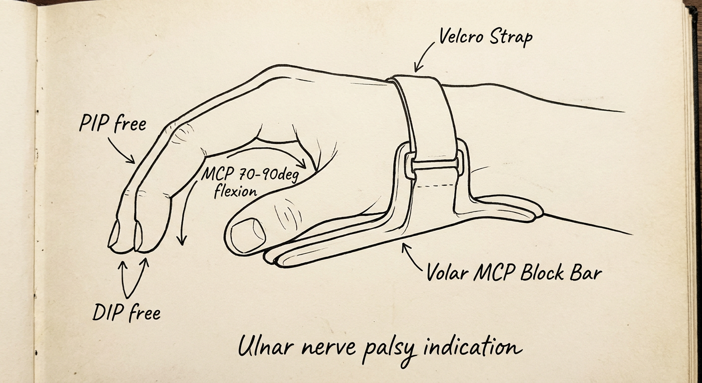
Key Components
| Component | Description |
|---|---|
| Volar MCP Block Bar | Thermoplastic bar on palm side blocking MCP hyperextension |
| MCP Joints | Blocked at 70-90° flexion |
| PIP Joints | FREE - full active range |
| DIP Joints | FREE |
| Thumb | FREE |
| Velcro Strap | Dorsal strap securing the block |
2. Dynamic MCP Flexion Orthosis
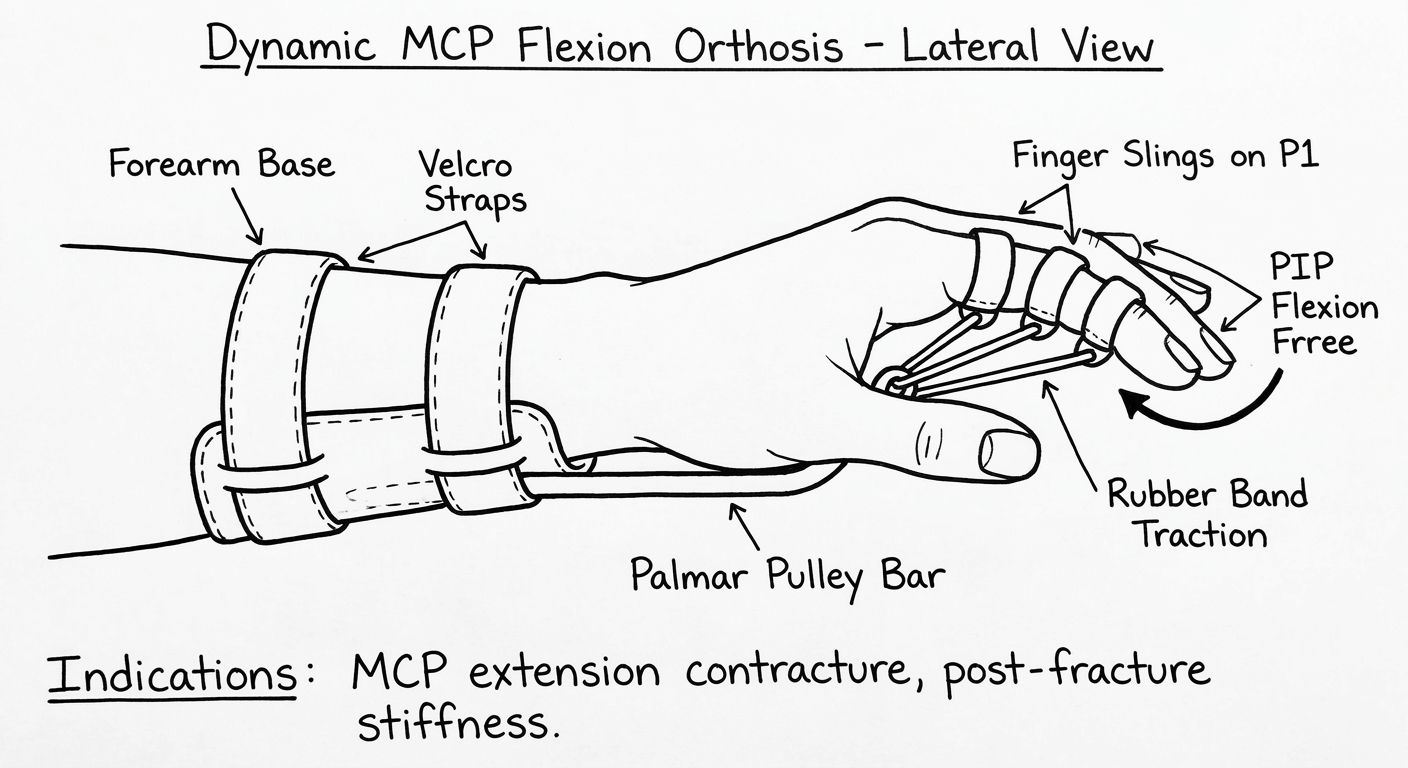
Key Components
| Component | Description |
|---|---|
| Forearm Base | Thermoplastic anchor extending from mid-forearm |
| Palmar Pulley Bar | Redirects elastic force toward the palm |
| Finger Slings on P1 | Loops placed on proximal phalanx of each finger |
| Rubber Band Traction | Pulls MCPs dynamically into flexion |
| Flexion Force | Directed palmarly toward the palm crease |
| PIP + DIP Joints | Completely FREE |
| Thumb | FREE |
| Velcro Straps | Secure forearm base |
Key Difference Between the Two
| Feature | Anti-Claw Splint | Dynamic MCP Flexion Orthosis |
|---|---|---|
| Type | Static blocking | Dynamic traction |
| Purpose | Restore function in nerve palsy | Increase MCP flexion ROM |
| MCP position | Held at 70-90° (blocked) | Pulled progressively into flexion |
| PIP/DIP | Free | Free |
| Use timing | During nerve recovery | Post-fracture / contracture rehab |
| Rubber bands | None | Yes - rubber band traction |
Dynamic pip extension orthosis and hand based functional orthosis
Black and white medical line art diagram of Dynamic PIP Extension Orthosis lateral view on a single finger. Hand-based or finger-based thermoplastic base on proximal phalanx, small dorsal outrigger or spring wire projecting over PIP joint, rubber band or coil spring pulling middle phalanx into extension, PIP joint being dynamically extended, DIP joint free, MCP joint free, securing strap on proximal phalanx. Labels: Proximal Phalanx Base, Dorsal Outrigger or Spring, Rubber Band Traction, Middle Phalanx attachment, PIP Joint dynamically extended, DIP FREE, MCP FREE, Securing Strap. Indications: PIP flexion contracture, Boutonniere late stage, Post-fracture PIP stiffness. Clean student OT notes style.
Black and white medical line art diagram of Hand-Based Functional Orthosis shown dorsal and lateral view. Hand-based thermoplastic splint covering the palm and metacarpal area only, wrist free, MCP joints supported in 70-90 degrees flexion, thumb in palmar abduction and opposition, fingers in functional position slight flexion, IP joints free, C-bar maintaining first web space, velcro strap across dorsum. Labels: Hand-Based Thermoplastic Base, C-Bar first web space, Thumb in Opposition, MCP Joints 70-90 degrees, Fingers in Functional Position, IP Joints Free, Wrist FREE, Velcro Strap. Indications: Median nerve palsy, Functional hand positioning, Post-CVA hand, Burns functional position. Clean student OT notes style.
400, message: Got more than 4194304 bytes when reading: b'data: {"candidates": [{"content": {"role": "model","parts": [{"inlineData": {"mimeType": "image/png"...'.
We encountered an error while processing your request. Please try again or reach out to us for help.
Dynamic pip extension orthosis and hand based functional orthosis
An error occurred (ValidationException) when calling the ConverseStream operation: Expected toolResult blocks at messages.90.content for the following Ids: tooluse_rjF7ZcFkA3cbk7A2PeulJn
We encountered an error while processing your request. Please try again or reach out to us for help.