Mechanism of normal labour

Reading File
Finding Sources
Finding Sources
Searching Images

mechanism of normal labour cardinal movements
A series of four clinical photographs demonstrating the cardinal movements of the human thumb at the carpometacarpal (CMC) joint. The hand is shown in four distinct positions, labeled with medical abbreviations: 'Ab' for Abduction, showing the thumb moving away from the palm in a sagittal plane; 'Ad' for Adduction, showing the thumb returned toward the radial side of the palm; 'F' for Flexion, depicting the thumb moving across the palm toward the ulnar side; and 'E' for Extension, showing the thumb moving away from the palm in the frontal plane. The images highlight the Range of Motion (ROM) and kinematic capabilities of the thumb's first metacarpal. This visual is used in physical therapy, orthopedics, and prosthetic design to define anatomical landmarks and standard functional assessments of the thumb's degree of freedom (DOF) and ability to perform opposition and repositioning tasks.
A series of four clinical photographs demonstrating the cardinal movements of the human thumb at the carpometacarpal (CMC) joint. The hand is shown in four distinct positions, labeled with medical abbreviations: 'Ab' for Abduction, showing the thumb moving away from the palm in a sagittal plane; 'Ad' for Adduction, showing the thumb returned toward the radial side of the palm; 'F' for Flexion, depicting the thumb moving across the palm toward the ulnar side; and 'E' for Extension, showing the thumb moving away from the palm in the frontal plane. The images highlight the Range of Motion (ROM) and kinematic capabilities of the thumb's first metacarpal. This visual is used in physical therapy, orthopedics, and prosthetic design to define anatomical landmarks and standard functional assessments of the thumb's degree of freedom (DOF) and ability to perform opposition and repositioning tasks.

This diagnostic image is a diffusion tensor tractography (DTT) reconstruction overlaid on a grayscale MRI axial slice of the human brain, illustrating five proposed recovery mechanisms for the injured anterior cingulum. The visualization uses colored dotted arrows to represent neural tract trajectories. Mechanism 1 (yellow) shows the normal pathway of the cingulum descending to the basal nucleus of Meynert (Ch. 4). Mechanism 2 (green) depicts a curved pathway descending toward the brainstem cholinergic nuclei. Mechanism 3 (blue) represents the lateral cholinergic pathway extending toward the temporo-occipital white matter. Mechanism 4 (red) demonstrates an interhemispheric tract connecting the contralesional and ipsilesional basal forebrains via the genu of the corpus callosum. Mechanism 5 (purple) illustrates an aberrant pathway from the injured cingulum also terminating at Ch. 4. The diagram serves as an educational model for neuroplasticity and cholinergic system compensation following brain injuries such as traumatic brain injury (TBI) or stroke, highlighting specific neuroanatomical landmarks including the brainstem, basal forebrain, and cingulate cortex.
This diagnostic image is a diffusion tensor tractography (DTT) reconstruction overlaid on a grayscale MRI axial slice of the human brain, illustrating five proposed recovery mechanisms for the injured anterior cingulum. The visualization uses colored dotted arrows to represent neural tract trajectories. Mechanism 1 (yellow) shows the normal pathway of the cingulum descending to the basal nucleus of Meynert (Ch. 4). Mechanism 2 (green) depicts a curved pathway descending toward the brainstem cholinergic nuclei. Mechanism 3 (blue) represents the lateral cholinergic pathway extending toward the temporo-occipital white matter. Mechanism 4 (red) demonstrates an interhemispheric tract connecting the contralesional and ipsilesional basal forebrains via the genu of the corpus callosum. Mechanism 5 (purple) illustrates an aberrant pathway from the injured cingulum also terminating at Ch. 4. The diagram serves as an educational model for neuroplasticity and cholinergic system compensation following brain injuries such as traumatic brain injury (TBI) or stroke, highlighting specific neuroanatomical landmarks including the brainstem, basal forebrain, and cingulate cortex.

A clinical photograph of an infant in a supine position, overlaid with a motion analysis coordinate system for the General Movement Assessment (GMA). The visual illustrates the quantitative analysis of spontaneous movements, specifically writhing movements (WM). A blue Cartesian coordinate system is centered on the infant's right shoulder joint, with axes normalized to the length of the analyzed limb. The vertical axis is oriented toward the head, and the horizontal axis is oriented toward the body midline. An orange ellipse is circumscribed over the trajectory of the right wrist, representing a 30-second observation period. The ellipse features internal black lines marking its major and minor axes, with a numerical value of 0.46 indicated. A large blue shaded circle represents the maximum possible range of motion used to calculate the Fraction of Movement Area (FMA). This methodology is used in neonatal neurology to differentiate normal spontaneous movements from poor repertoire (PR) movements, serving as a diagnostic tool for early detection of neurodevelopmental disorders such as cerebral palsy.
A clinical photograph of an infant in a supine position, overlaid with a motion analysis coordinate system for the General Movement Assessment (GMA). The visual illustrates the quantitative analysis of spontaneous movements, specifically writhing movements (WM). A blue Cartesian coordinate system is centered on the infant's right shoulder joint, with axes normalized to the length of the analyzed limb. The vertical axis is oriented toward the head, and the horizontal axis is oriented toward the body midline. An orange ellipse is circumscribed over the trajectory of the right wrist, representing a 30-second observation period. The ellipse features internal black lines marking its major and minor axes, with a numerical value of 0.46 indicated. A large blue shaded circle represents the maximum possible range of motion used to calculate the Fraction of Movement Area (FMA). This methodology is used in neonatal neurology to differentiate normal spontaneous movements from poor repertoire (PR) movements, serving as a diagnostic tool for early detection of neurodevelopmental disorders such as cerebral palsy.

This pathophysiology diagram illustrates the neurobiological mechanism of Premenstrual Dysphoric Disorder (PMDD) focusing on allopregnanolone (ALLO) and GABAA receptor signaling. The diagram is divided into 'Normal' (left) and 'PMDD' (right) physiological states. In the 'Normal' state, higher ALLO levels maintain the function of extrasynaptic alpha-4 beta-delta GABAA receptors on GABAergic interneurons, leading to robust GABA release and effective tonic inhibition of pyramidal neurons, shown with low excitability. In the 'PMDD' state, a rapid decline in ALLO (indicated by multiple downward arrows) is shown alongside altered GABAergic interneurons. This leads to reduced GABA release and a subsequent 'disinhibition' of the postsynaptic pyramidal neuron. The clinical consequence is visualized as increased pyramidal neuron excitability, labeled as 'PMDD-like symptoms.' Key components include labeled GABAergic interneurons, pyramidal neurons with electrophysiological excitability inserts, and extrasynaptic receptor subunits. This content is intended for advanced medical education in psychiatry and neuroendocrinology.

This pathophysiology diagram illustrates the neurobiological mechanism of Premenstrual Dysphoric Disorder (PMDD) focusing on allopregnanolone (ALLO) and GABAA receptor signaling. The diagram is divided into 'Normal' (left) and 'PMDD' (right) physiological states. In the 'Normal' state, higher ALLO levels maintain the function of extrasynaptic alpha-4 beta-delta GABAA receptors on GABAergic interneurons, leading to robust GABA release and effective tonic inhibition of pyramidal neurons, shown with low excitability. In the 'PMDD' state, a rapid decline in ALLO (indicated by multiple downward arrows) is shown alongside altered GABAergic interneurons. This leads to reduced GABA release and a subsequent 'disinhibition' of the postsynaptic pyramidal neuron. The clinical consequence is visualized as increased pyramidal neuron excitability, labeled as 'PMDD-like symptoms.' Key components include labeled GABAergic interneurons, pyramidal neurons with electrophysiological excitability inserts, and extrasynaptic receptor subunits. This content is intended for advanced medical education in psychiatry and neuroendocrinology.

Finding Sources
Finding Sources
Searching Images

cardinal movements of labour engagement descent flexion rotation fetus
Clinical photograph of a fetus's lower limbs and feet, demonstrating multiple congenital malformations. The feet show severe bilateral talipes equinovarus (clubfoot), characterized by inward and downward rotation with excessive plantar flexion. Postaxial polydactyly is evident on at least one foot, which presents with six digits. The skin appears pale to cyanotic (bluish tint) with evidence of desquamation and epidermal sloughing, potentially indicating post-mortem changes or intrauterine distress. Traces of blood and vernix caseosa are visible on the skin surface. These findings are consistent with polymalformative conditions, such as Meckel-Gruber syndrome, which often involves multisystem congenital defects including limb and digit abnormalities. The photograph serves as an educational example of macroscopic fetal pathology for pediatrics, genetics, and obstetrics.
Clinical photograph of a fetus's lower limbs and feet, demonstrating multiple congenital malformations. The feet show severe bilateral talipes equinovarus (clubfoot), characterized by inward and downward rotation with excessive plantar flexion. Postaxial polydactyly is evident on at least one foot, which presents with six digits. The skin appears pale to cyanotic (bluish tint) with evidence of desquamation and epidermal sloughing, potentially indicating post-mortem changes or intrauterine distress. Traces of blood and vernix caseosa are visible on the skin surface. These findings are consistent with polymalformative conditions, such as Meckel-Gruber syndrome, which often involves multisystem congenital defects including limb and digit abnormalities. The photograph serves as an educational example of macroscopic fetal pathology for pediatrics, genetics, and obstetrics.

This Comparison Chart displays three-dimensional Finite Element (FE) biomechanical models of the lumbosacral spine, contrasting a 'Healthy' model with a 'Degenerated' model (specifically targeting the L5-S1 disc level). The image is organized into a 4x2 grid demonstrating four fundamental spinal movements: Flexion (labeled FleZion), Extension (labeled EZtension), Lateral Bending, and Axial Rotation. Each movement is depicted using a green wireframe mesh representing the deformed state, overlaid against a semi-transparent white outline representing the neutral anatomical position. In the sagittal plane movements (flexion and extension), the healthy model demonstrates greater spinal arc curvature and range of motion compared to the degenerated model, which appears more rigid. Similarly, the coronal view for lateral bending shows more significant vertebral displacement in the healthy spine. The axial rotation view (superior-inferior perspective) illustrates the rotational torque and displacement of the vertebral bodies. These models serve as an educational tool for studying the biomechanical impact of intervertebral disc degeneration on spinal mobility and structural mechanics across the L1 to S1 segments.
This Comparison Chart displays three-dimensional Finite Element (FE) biomechanical models of the lumbosacral spine, contrasting a 'Healthy' model with a 'Degenerated' model (specifically targeting the L5-S1 disc level). The image is organized into a 4x2 grid demonstrating four fundamental spinal movements: Flexion (labeled FleZion), Extension (labeled EZtension), Lateral Bending, and Axial Rotation. Each movement is depicted using a green wireframe mesh representing the deformed state, overlaid against a semi-transparent white outline representing the neutral anatomical position. In the sagittal plane movements (flexion and extension), the healthy model demonstrates greater spinal arc curvature and range of motion compared to the degenerated model, which appears more rigid. Similarly, the coronal view for lateral bending shows more significant vertebral displacement in the healthy spine. The axial rotation view (superior-inferior perspective) illustrates the rotational torque and displacement of the vertebral bodies. These models serve as an educational tool for studying the biomechanical impact of intervertebral disc degeneration on spinal mobility and structural mechanics across the L1 to S1 segments.

A series of clinical photographs illustrating lower limb range of motion (ROM) exercises and biomechanics. The images are categorized into four panels (A-D), each demonstrating specific joint movements used in musculoskeletal assessment and physical therapy. Panel A shows sagittal view knee extension (left) and knee flexion (right), with curved red arrows indicating the arc of motion. Panel B displays hip/femoral rotation, featuring external (lateral) rotation (left) and internal (medial) rotation (right) in a seated position. Panel C demonstrates ankle kinematics, specifically dorsiflexion (left) and plantar flexion (right). Panel D illustrates transverse plane tibial rotation, showing lateral rotation (left) and medial rotation (right). These visuals serve as a clinical guide for identifying standard non-weight-bearing movements, useful for studying motor patterns, surface electromyography (sEMG) electrode placement, and rehabilitation protocols for lower limb conditions or phantom limb pain treatment.
A series of clinical photographs illustrating lower limb range of motion (ROM) exercises and biomechanics. The images are categorized into four panels (A-D), each demonstrating specific joint movements used in musculoskeletal assessment and physical therapy. Panel A shows sagittal view knee extension (left) and knee flexion (right), with curved red arrows indicating the arc of motion. Panel B displays hip/femoral rotation, featuring external (lateral) rotation (left) and internal (medial) rotation (right) in a seated position. Panel C demonstrates ankle kinematics, specifically dorsiflexion (left) and plantar flexion (right). Panel D illustrates transverse plane tibial rotation, showing lateral rotation (left) and medial rotation (right). These visuals serve as a clinical guide for identifying standard non-weight-bearing movements, useful for studying motor patterns, surface electromyography (sEMG) electrode placement, and rehabilitation protocols for lower limb conditions or phantom limb pain treatment.

This educational graphic illustrates the procedural steps and anatomical considerations for Vacuum-Assisted Delivery (VAD). Panel A, 'Cup Placement', features a superior-view diagram of a fetal skull and a clinical photograph. It defines the 'flexion point' along the sagittal suture, located 6 cm from the anterior fontanelle and 3 cm from the posterior fontanelle. A sagittal cross-section shows the fetus in the uterus, identifying landmarks like the pubic symphysis, sacrum, and stations of delivery (0 to +3). Panel B, 'Traction', demonstrates the application of force. One hand provides 'Applied Traction' along the pelvic axis, while the other provides 'Counter Traction' at the introitus to stabilize the vacuum cup. Panel C, 'Cup Release', depicts the removal of the vacuum device once the fetal head has successfully crowned. This diagram is designed for obstetrics education, emphasizing correct cup positioning to facilitate head flexion and descent through the birth canal while minimizing maternal and neonatal trauma.

This educational graphic illustrates the procedural steps and anatomical considerations for Vacuum-Assisted Delivery (VAD). Panel A, 'Cup Placement', features a superior-view diagram of a fetal skull and a clinical photograph. It defines the 'flexion point' along the sagittal suture, located 6 cm from the anterior fontanelle and 3 cm from the posterior fontanelle. A sagittal cross-section shows the fetus in the uterus, identifying landmarks like the pubic symphysis, sacrum, and stations of delivery (0 to +3). Panel B, 'Traction', demonstrates the application of force. One hand provides 'Applied Traction' along the pelvic axis, while the other provides 'Counter Traction' at the introitus to stabilize the vacuum cup. Panel C, 'Cup Release', depicts the removal of the vacuum device once the fetal head has successfully crowned. This diagram is designed for obstetrics education, emphasizing correct cup positioning to facilitate head flexion and descent through the birth canal while minimizing maternal and neonatal trauma.

Reading File
Reading File
Loading Image
Reading File
I now have comprehensive content and an excellent diagram. Let me compile the full answer.

Mechanism of Normal Labour (Cardinal Movements)
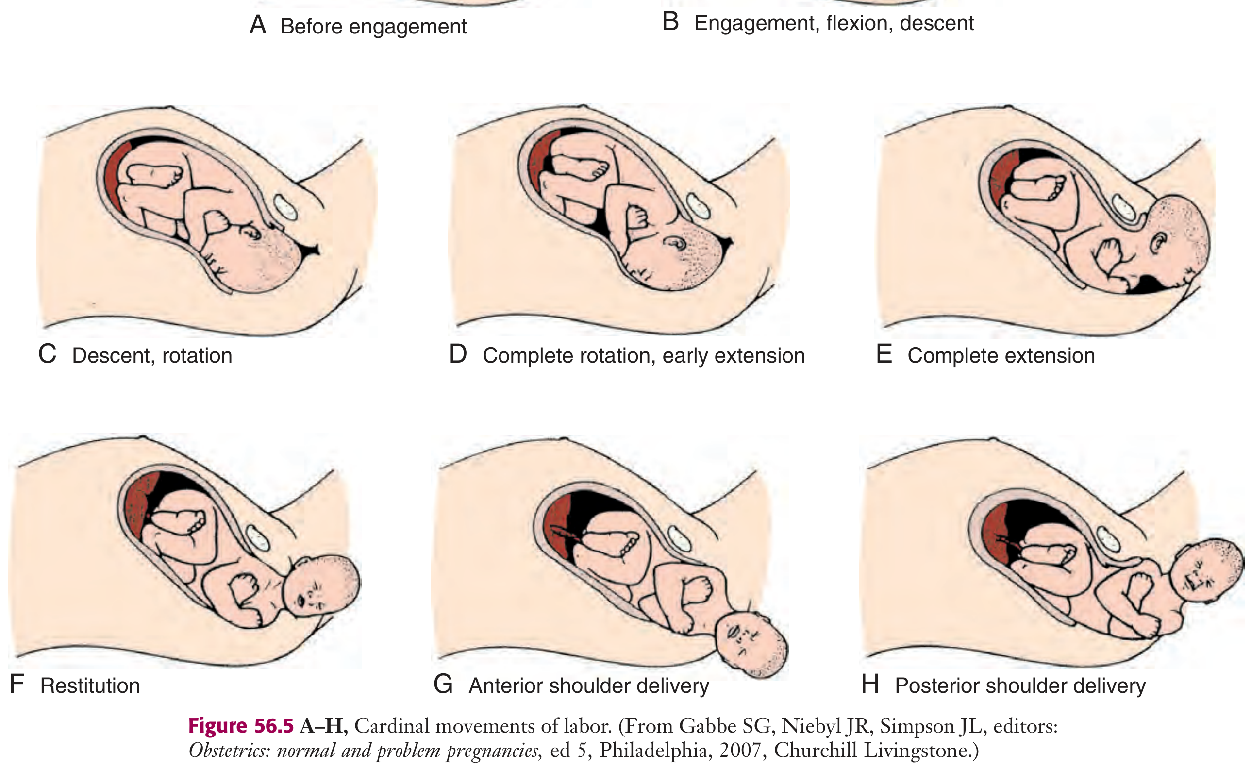
The mechanism of labour refers to the series of movements the fetus undergoes as it negotiates the birth canal. These are collectively called the cardinal movements of labour. They are determined by three factors: pelvic dimensions and configuration, fetal size, and strength of uterine contractions. The fetus follows the path of least resistance, adapting its smallest achievable diameter to the most favourable dimensions of the birth canal.
In vertex (cephalic) presentations, there are 7 cardinal movements:

Cardinal movements of labor - Roberts & Hedges
Fig. 56.5 - Cardinal movements of labor (A: before engagement; B: engagement, flexion, descent; C: descent, rotation; D: complete rotation, early extension; E: complete extension; F: restitution; G: anterior shoulder delivery; H: posterior shoulder delivery) - Roberts & Hedges' Clinical Procedures in Emergency Medicine

1. Engagement

Engagement is the mechanism by which the greatest transverse diameter of the fetal head - the biparietal diameter (BPD) in occiput presentations (~9.5 cm) - passes through the pelvic inlet. The fetus is engaged when the presenting part is at station 0 (at the level of the ischial spines).
  • In primigravidas: occurs in the last 2 weeks of pregnancy ("lightening")
  • In multigravidas: may occur only at the onset of labour
  • The head engages most commonly in the left occiput transverse (LOT) or right occiput transverse (ROT) position

2. Flexion

The fetal head flexes so that the chin is brought onto the chest, minimising the presenting cross-sectional diameter. This changes the presenting diameter from the occipitofrontal (~11 cm) to the suboccipitobregmatic diameter (~9.5 cm), which is the smallest diameter. Flexion is a passive movement occurring as the head meets resistance from the pelvic floor and walls. It is necessary for both engagement and descent.

3. Descent

Descent is the downward passage of the presenting part through the birth canal. It is progressive but not necessarily continuous. Descent is driven by:
  • Uterine contractions (the primary force)
  • Abdominal muscle contractions (voluntary bearing down)
  • Straightening and extension of the fetal body
  • Amniotic fluid pressure
Descent begins during engagement and continues throughout labour. It accelerates during the second stage.

4. Internal Rotation

As the head descends and reaches the level of the ischial spines, it undergoes internal rotation. The occiput gradually rotates from its original (more transverse) position anteriorly toward the symphysis pubis. This is the normal occiput anterior (OA) position.
  • The rotation brings the longest diameter of the head (anteroposterior) in line with the longest diameter of the pelvic outlet
  • Less commonly, the occiput rotates posteriorly toward the hollow of the sacrum - called occiput posterior (OP) position
  • Internal rotation is necessary to traverse the ischial spines

5. Extension

As the flexed head reaches the anteriorly directed vaginal introitus, it undergoes extension. The occiput impinges under the pubic arch (the symphysis acts as a pivot/fulcrum), and the head extends around it. In sequence, the occiput, bregma, forehead, nose, mouth, and chin pass successively over the anterior margin of the perineum.
  • Extension delivers the head
  • Immediately after delivery, the head drops downward so the chin lies over the maternal anal region

6. External Rotation (Restitution)

After delivery of the head, it undergoes external rotation, returning to the correct anatomic position with respect to the fetal torso. The head rotates to the transverse position it occupied at engagement. This is a passive movement and reflects the alignment of the shoulders in the anteroposterior diameter of the pelvic outlet.
  • "Restitution" = the head rotating back to its natural relationship with the shoulders
  • Followed by further rotation as the shoulders align for delivery

7. Expulsion

The remainder of the fetal body is delivered. The shoulders descend in a path similar to that traced by the head - rotating anteroposteriorly for delivery. The sequence is:
  1. Anterior shoulder delivered beneath the symphysis pubis (by lateral flexion of trunk toward mother's abdomen)
  2. Posterior shoulder delivered across the perineum
  3. The rest of the body follows rapidly

Summary Table

MovementKey Diameter / AxisPassive/ActiveClinical Significance
EngagementBPD passes inlet-Station 0; lightening in primigravidas
FlexionSuboccipitobregmatic presentedPassiveReduces presenting diameter
DescentAlong pelvic axisActive (contractions)Driven by uterine + abdominal forces
Internal rotationOcciput to anterior (OA)PassiveAllows head to negotiate ischial spines
ExtensionAround pubic symphysisPassiveDelivers the head
External rotationHead back to transversePassiveAligns shoulders for delivery
ExpulsionShoulders + bodyActiveAnterior then posterior shoulder

Key Anatomical Points

  • Presenting diameter in flexed vertex: suboccipitobregmatic = ~9.5 cm (vs. occipitofrontal = 11.5 cm in deflexed head)
  • Reference point: the occiput in vertex presentations; the sacrum in breech
  • Station: measured in cm above (-) or below (+) the ischial spines
  • Normal position: Left Occiput Anterior (LOA) is the most common position at delivery

Sources: Roberts & Hedges' Clinical Procedures in Emergency Medicine (Fig. 56.5, pp. 1351-1352); Tintinalli's Emergency Medicine, 9th ed.; Textbook of Family Medicine, 9th ed.
This is a shared conversation. Sign in to Orris to start your own chat.