
Hey, I m Tushar Kumar, I m Puersing my degree in bsc anaesthesia and operations theatre technology, I need answer according to my degree,
What would you like help with today?
Tell about Et tube in detailed and tell me about how it is work during the intubation like insert into vocal code , bronchia tree
endotracheal tube anatomy parts diagram
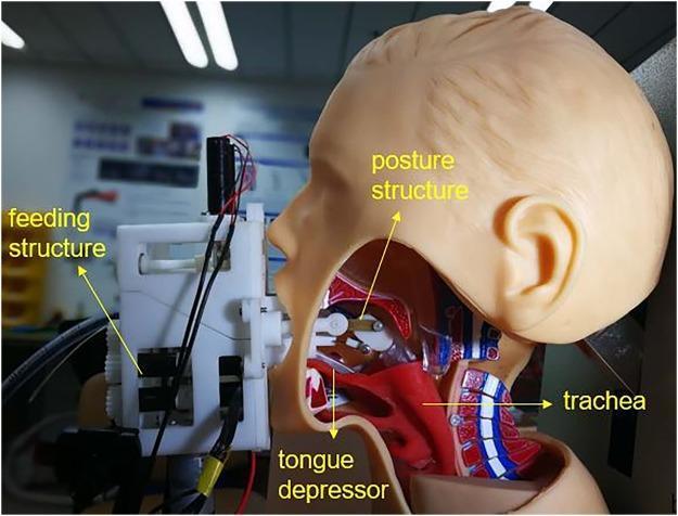
This clinical photograph/diagram shows a lateral cross-section of a medical manikin used to demonstrate a robotic-assisted intubation system. The image illustrates the mechanical interface between the 'Remote Robot-Assisted Intubation System' (RRAIS) and human upper airway anatomy. Key visible components include an external feeding structure situated at the mouth, which houses the mechanism for advancing the endotracheal tube. A robotic tongue depressor is shown inserted into the oral cavity, making contact with the base of the tongue to facilitate glottis exposure. Internally, a 'posture structure' is positioned within the oropharynx to control the tube's tip orientation. Anatomical landmarks labeled on the manikin's sagittal view include the tongue, oral cavity, and the trachea, demonstrating the intended pathway for the airway device. This visual serves as an educational tool for anesthesiology and emergency medicine, highlighting technological advancements in airway management and the mechanics of remote-controlled endotracheal intubation.
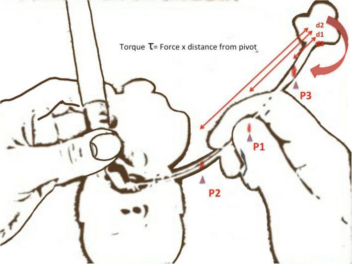
This medical illustration demonstrates the physics of torque during endotracheal intubation. The diagram shows a clinician's hands manipulating an endotracheal tube (ETT) through a patient's mouth using a laryngoscope. The focus is on the biomechanics of tube tip control. Three specific holding points on the ETT are labeled: P1 (proximal), P2 (middle), and P3 (distal, furthest from the tip). Annotations include the formula 'Torque τ = Force x distance from pivot'. Red arrows indicate the distance (d1, d2) from holding points to the distal tip. A large red curved arrow at the tip represents the ease of rotation. The educational purpose is to illustrate that as the holding point (pivot) moves further from the tip (e.g., at P3), the mechanical advantage increases, allowing for finer, more effortless adjustments of the tube tip movement toward the glottic opening. This concept is vital for anesthesiology and emergency medicine trainees to improve intubation success rates and maneuverability.
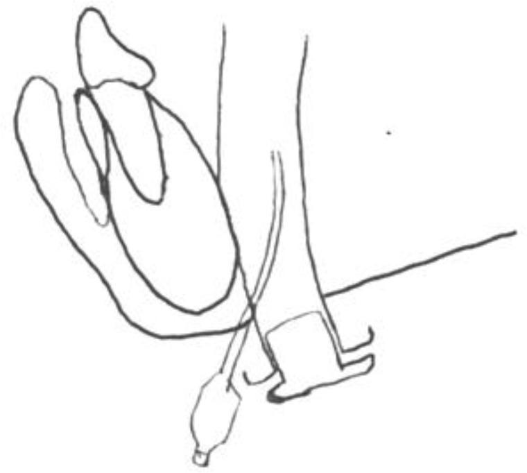
This medical illustration is a line diagram depicting the anatomical route of the original subperiosteal midline submental intubation technique. The diagram shows a sagittal-oblique view of the oral cavity and neck structures. Key anatomical landmarks include the mandible (anteriorly) and the floor of the mouth. An endotracheal tube is illustrated following a submental trajectory, entering from the submental skin through a midline incision and passing superiorly into the oral cavity, medial to the mandibular border. The cuff of the armored anesthetic tube is shown positioned in the sublingual space. The illustration highlights the spatial relationship between the intubation tube and the oral floor, designed to facilitate airway management in complex maxillofacial surgeries where oral or nasal intubation is contraindicated. This diagram serves as an educational tool for anesthesiology and oral-maxillofacial surgery, specifically demonstrating the Altemir technique and its associated anatomical risks, such as potential damage to sublingual vascular structures during subperiosteal dissection.
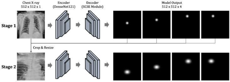
A technical diagram illustrating a two-stage deep learning architecture for key point detection in chest radiography, specifically designed to evaluate endotracheal tube (ETT) positioning. Stage 1 takes a full-field chest X-ray (512x512x1) as input, passing it through a DenseNet121 encoder and a decoder with a Spatial and Channel Squeeze & Excitation (SCSE) module. The output is a set of four heatmaps representing the initial localization of four clinical key points: the tracheal tube end, the carina, and the left and right clavicular heads. In Stage 2, the process is refined by cropping and resizing the region of interest based on Stage 1 results, passing it through identical encoder-decoder blocks to produce high-resolution probability distributions of the target coordinates. The model facilitates clinical assessment by calculating distances between these anatomical landmarks to determine if the ETT position is appropriate (typically 20–70 mm from the carina). This tool is intended for medical AI research and radiology computer-aided diagnosis training.
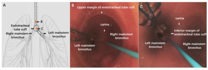
This composite educational resource illustrates the positioning of an endotracheal tube (ETT) for lung isolation and hemorrhage control. Panel A is an anatomical diagram showing the ETT tip positioned within the left mainstem bronchus, with the inflated cuff situated at the carina to isolate the right lung. Panels B and C are bronchoscopic images captured via a flexible electronic bronchoscope. Image B demonstrates the view from within the trachea, showing the upper margin of the inflated ETT cuff, the carina, and the openings to the left and right mainstem bronchi. Image C provides a view from a more distal position, identifying the carina and the inferior margin of the cuff as it sits at the tracheal bifurcation. This content is designed to teach airway management, one-lung ventilation techniques, and compression hemostasis protocols for managing massive hemoptysis or pulmonary hemorrhage.
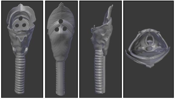
Anatomical Diagram/3D Model: This image displays a grey-scale 3D digital rendering of a pediatric throat piece designed for a medical simulation model, shown in four standard orientations: anterior, posterior, lateral, and cranial-caudal (superior) views. The model illustrates the essential upper airway anatomy required for Endotracheal Intubation (ETI) training. The anterior and lateral views highlight the distal trachea characterized by prominent horizontal ridges representing tracheal rings. The proximal portion includes the laryngeal structures and esophagus, featuring three circular registration holes for assembly with a head unit. The cranial-caudal view provides an internal perspective of the airway, depicting an oval-shaped glottic opening and vocal cord structures surrounded by simulated soft tissues. This model is constructed from flexible materials to mimic the tactile feel of human tissue, serving as a pedagogical tool for medical students and clinicians to practice airway management and recognize key anatomical landmarks such as the larynx, trachea, and esophagus.
intubation endotracheal tube vocal cords trachea insertion
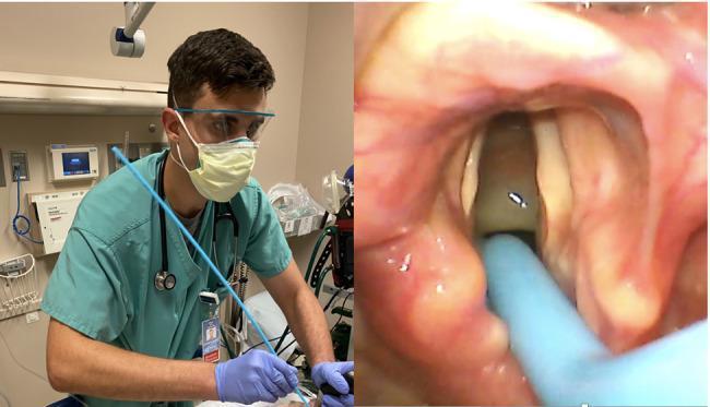
This composite clinical photograph illustrates an endotracheal intubation procedure using a tracheal tube introducer (bougie). The left panel shows the clinical setup where an emergency medicine resident, in appropriate personal protective equipment (mask, eye protection, and gloves), is performing the procedure. He is holding a blue bougie with his right arm adducted to optimize the angle of insertion. The right panel displays the corresponding real-time video laryngoscope view within the oropharynx. This internal view reveals the epiglottis, arytenoids, and the vocal cords (Cormack-Lehane Grade 2a). The blue tip of the bougie is visible passing through the glottic opening into the trachea, demonstrating successful placement. The content emphasizes the relationship between clinician ergonomics, specifically shoulder position, and the successful navigation of airway adjuncts during rapid sequence intubation (RSI) for respiratory failure.
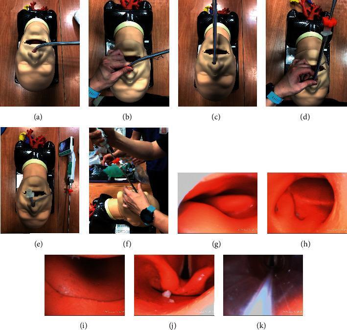
This composite educational image illustrates the multi-step process of nasotracheal intubation using a Trachway video stylet, demonstrated on a medical mannequin. Panels (a) through (f) provide a superior view of the external clinical technique, showing the insertion of the endotracheal tube (ETT) into the nostril, followed by a 90-degree rotation and elevation to the midline to align the stylet with the anatomical curve of the nasopharynx. Panels (g) through (k) display the concurrent internal endoscopic views captured by the stylet's camera. These internal frames demonstrate the advancement through the nasopharynx (g, h), the transition into the oropharynx (i), and the direct visualization of the laryngopharynx and glottic opening (j). The final frame (k) confirms successful placement as the ETT tip passes through the vocal cords into the trachea. This content demonstrates difficult airway management techniques, highlighting the use of video-assisted stylets to facilitate visualization without requiring significant head or neck manipulation, which is essential in patients with limited mouth opening or cervical spine precautions.
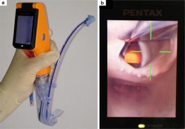
This composite image illustrates the design and clinical application of the Airway Scope® (AWS), a portable, battery-operated video-laryngoscope used for endotracheal intubation. Figure A shows the device's physical components: an orange handle with an integrated 6.1 cm LCD monitor and a single-use 'Intlock' blade. An endotracheal tube (ETT) with a blue radiopaque stripe is preloaded into the blade’s dedicated side-channel guide, which facilitates direct advancement into the trachea. Figure B demonstrates the device's functional output during indirect laryngoscopy. The LCD screen displays a real-time view of the upper airway, specifically focusing on the glottic opening. To assist the clinician, a green crosshair target is superimposed on the digital image; alignment of this target with the glottis indicates the correct path for ETT insertion. This visual aid is designed to simplify intubation by providing a wide viewing angle (180°) and clear anatomical visualization of the vocal cords, thereby potentially increasing first-pass success rates in both novice and expert practitioners.
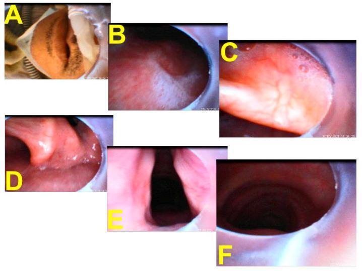
This composite of endoscopic images illustrates a serial pictorial progression of tracheal intubation using a video-assisted intubating stylet (Shikani technique). (A) Shows the clinical context of the patient receiving high-flow nasal cannula (HFNC) treatment just prior to insertion. (B) Displays the pharyngeal view with visible mucus and saliva at the start of the procedure. (C) Provides a close-up of the vallecula as the stylet advances. (D) Visualizes the corniculate and cuneiform cartilages of the posterior larynx. (E) Offers a clear, full view of the glottic opening and vocal cords, representing the target for endotracheal tube (ETT) placement. (F) Confirms successful placement by visualizing the internal tracheal rings and the distal tip of the ETT within the trachea. The images demonstrate the necessary anatomical landmarks for safe airway management, including the transition from the oropharynx through the glottis and into the subglottic space. This series is an educational example of real-time visualization used to guide airway management in high-risk patients, such as those with severe respiratory infections requiring rapid ventilator support.
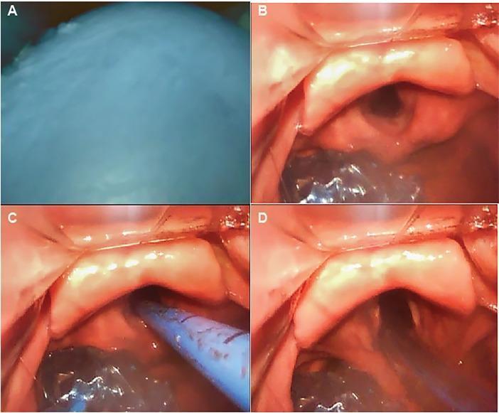
This sequence of four endoscopic images (A-D) demonstrates a Seldinger-style exchange of a King LT extraglottic device for a definitive tracheal tube under video laryngoscopy. Panel A shows the initial view of the inflated, opaque oropharyngeal balloon of the King LT obscuring the laryngeal inlet. Panel B illustrates the glottic view following balloon deflation and blade advancement into the vallecula, clearly revealing the epiglottis, arytenoid cartilages, and vocal cords. Panel C shows the insertion of a blue tracheal introducer (bougie) through the vocal cords into the trachea. Panel D depicts the final stage of advancing a cuffed endotracheal tube over the bougie into the airway. This clinical sequence provides an educational protocol for emergency airway management, specifically addressing the transition from supraglottic ventilation to endotracheal intubation in a controlled manner.
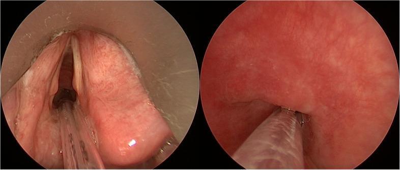
This endoscopic clinical photograph displays two laryngoscopic views of a patient with severe subglottic stenosis undergoing specialized intubation. The left panel shows a supraglottic view where the vocal cords appear as pale, whitish bands. The surrounding laryngeal mucosa is erythematous and congested. Centrally, a clear, ultrathin Tritube endotracheal tube is visible, inserted through a significantly narrowed subglottic opening. Small amounts of white, mucoid secretions are noted along the peripheral laryngeal structures. The right panel provides a subglottic view, demonstrating the distal portion of the clear endotracheal tube positioned within the trachea. The tracheal walls appear intensely erythematous and inflamed, with a concentric narrowing consistent with severe stenosis. There is a lack of normal tracheal rings' definition, indicating chronic inflammatory or cicatricial changes. This comparison highlights the anatomical challenges of managing a compromised airway and the use of small-lumen ventilation tubes to maintain oxygenation while maximizing surgical exposure in the laryngeal and tracheal regions.
Endotracheal (ET) Tube - Complete Guide
1. What is an ET Tube?
- Securing and maintaining a patent airway
- Delivering anaesthetic gases and oxygen directly to the lungs
- Enabling controlled mechanical ventilation
- Preventing aspiration of gastric contents into the lungs
2. Parts of an ET Tube (Anatomy)
| Part | Description |
|---|---|
| Connector (15 mm adapter) | Universal 15 mm connector at the top that attaches to the breathing circuit/ventilator |
| Tube body | Flexible, transparent PVC tube, approximately 30 cm long in adults |
| Cuff | Inflatable balloon near the distal end; creates a seal in the trachea |
| Pilot balloon | Small balloon outside the tube connected to the cuff - tells you the cuff is inflated |
| Inflation line | Connects pilot balloon to cuff |
| One-way valve | On the inflation line; holds air inside the cuff once inflated |
| Murphy eye | A side hole near the distal tip; allows gas to flow even if the main tip is blocked |
| Bevel tip | Angled distal end (bevel faces left); makes insertion through vocal cords easier |
| Centimetre markings | Printed along the tube body to measure depth of insertion at the teeth/gum |
| Radio-opaque line | A line running the length of the tube so it is visible on chest X-ray |
3. Tube Sizes (Internal Diameter)
| Patient | Tube Size (ID) |
|---|---|
| Adult Female | 7.0 - 8.0 mm |
| Adult Male | 7.5 - 9.0 mm |
| Child 5-6 years | 5.0 mm |
| Child 3-4 years | 4.5 mm |
| Child 1-2 years | 4.0 mm |
| Term newborn | 3.0 mm |
- Uncuffed ETT size = [Age (years) / 4] + 4
- Cuffed ETT size = [Age (years) / 4] + 3
4. Cuff - High-Volume, Low-Pressure Design
- Low pressure on the tracheal wall prevents pressure necrosis of the tracheal mucosa
- Capillary blood flow in the tracheal mucosa is compromised when cuff pressure exceeds 30 mmHg
- Ideal cuff pressure: 20-25 mmHg for long-term use
- Clinical test: slowly inject air until no audible leak during bag-mask ventilation - this usually takes 5-8 mL of air
- In emergencies: inflate with 10 mL air and adjust later
5. Step-by-Step Intubation Process
Pre-intubation Preparation
- Laryngoscope (check light)
- ET tube (check cuff - inflate and deflate to confirm no leak)
- Stylet inside the tube (gives rigidity and shape)
- 10 mL syringe for cuff inflation
- Suction
- Bag-valve-mask + oxygen
- End-tidal CO₂ colorimeter
Step 1 - Patient Positioning: "Sniffing Position"
- Neck flexed (pillow under the head)
- Head extended at the atlanto-occipital joint
Step 2 - Preoxygenation
Step 3 - Drugs (in Anaesthesia)
- IV induction agent (e.g., propofol, thiopentone) - renders the patient unconscious
- Muscle relaxant (e.g., suxamethonium for RSI, or rocuronium) - relaxes the jaw and vocal cords for easy passage of the tube
Step 4 - Laryngoscopy (Opening the View)
- Hold the laryngoscope in the LEFT hand
- Open the patient's mouth with the right hand
- Insert the laryngoscope blade into the right side of the mouth, sweeping the tongue to the LEFT (critical - if tongue is not swept left, it folds over the blade and blocks the view)
- Slowly advance the blade toward the base of the tongue
- Lift upward and forward at 45 degrees along the axis of the laryngoscope handle - do NOT use the teeth as a lever/fulcrum
Step 5 - Visualising the Vocal Cords
- Epiglottis (first landmark to identify - described as "epiglottoscopy")
- Below the epiglottis: the glottic opening (laryngeal inlet)
- The vocal cords appear as two pale white bands on either side, forming a V-shape (triangular glottis)
Do NOT attempt to pass the tube if vocal cords are not visible.
Step 6 - Inserting the ET Tube Through the Vocal Cords
- Hold the ET tube in the RIGHT hand
- Advance the tube tip through the glottic opening (between the vocal cords)
- The bevel (angled tip) faces left and helps navigate between the cords
- Advance until the cuff is just past (below) the vocal cords - approximately 2-3 cm below
- Once cuff clears the cords, remove the stylet
- Advance to 21 cm at the teeth for women, 22 cm for men
Step 7 - Cuff Inflation and Position in the Trachea
- Inflate the cuff with air using the 10 mL syringe via the pilot balloon
- The cuff should sit in the mid-trachea, well below the vocal cords
- The cuff creates a seal between the tube and tracheal wall, preventing:
- Leakage of gases
- Aspiration of secretions or gastric contents into the bronchial tree
Step 8 - Confirming Correct Position (Most Critical Step)
- End-tidal CO₂ colorimeter - turns yellow/green if CO₂ is detected (confirms tracheal placement, not oesophageal)
- Auscultation - bilateral equal breath sounds over both lung fields; no sounds over the stomach
- Chest rise - symmetrical on both sides
- Chest X-ray - tube tip should be at the level of the carina + 2-3 cm (roughly at T4-T5 level)
- Fogging in the tube during exhalation (less reliable on its own)
6. What Happens in the Bronchial Tree
Mouth → Pharynx → Larynx (past vocal cords) → Trachea → TUBE TIP STOPS HERE
                                                     ↓
                                              Carina (bifurcation)
                                            ↙               ↘
                               Right mainstem            Left mainstem
                               bronchus                  bronchus
- Only the right lung ventilated
- Left lung collapses
- Decreased SpO₂, asymmetrical chest movement
- Fix: pull tube back slowly until bilateral breath sounds are equal
7. Complications Related to the Vocal Cords and Trachea
| Complication | Cause |
|---|---|
| Vocal cord injury | Repeated forceful intubation attempts; excessive cuff pressure against underside of vocal cords |
| Tracheal mucosal necrosis | Cuff pressure > 30 mmHg for prolonged periods |
| Accidental oesophageal intubation | Tube in wrong place - immediately detected by CO₂ monitor |
| Right mainstem endobronchial intubation | Tube advanced too far |
| Subglottic stenosis | Long-term intubation injury |
8. Quick Summary Table
| Feature | Detail |
|---|---|
| Material | Transparent PVC |
| Adult female size | 7.0-8.0 mm ID |
| Adult male size | 7.5-9.0 mm ID |
| Cuff type | High-volume, low-pressure |
| Ideal cuff pressure | 20-25 mmHg |
| Insertion depth (female) | 21 cm at teeth |
| Insertion depth (male) | 22 cm at teeth |
| Tube tip position | 3-7 cm above carina (mid-trachea) |
| Confirmation | EtCO₂ + auscultation + CXR |