
Supra orbital fissure in detail in simplified manner according to standard ENT textbook and along with images explaining everything about it and that is supposed to be drawn in exam
superior orbital fissure anatomy diagram structures passing through
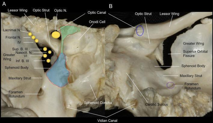
This medical anatomical diagram features two clinical photographs of a dry bone specimen, showing the osseous anatomy of the human orbital apex of the sphenoid bone. Image (A) provides an anterior view, highlighting the optic canal superomedially and the superior orbital fissure (SOF) inferolaterally. Key landmarks include the optic strut, which separates the optic nerve and ophthalmic artery from the SOF contents, and the maxillary strut, which separates the SOF from the foramen rotundum. Overlays illustrate the surgical decompression areas: the light green area denotes the medial wall of the optic canal, and the light blue area indicates the medial wall of the SOF. Image (B) presents a posterior view, showing the spatial relationship between the optic canal, SOF, foramen rotundum, and the carotid sulcus. The diagram identifies neurovascular structures passing through these apertures, including the optic nerve (CN II), oculomotor nerve (CN III), trochlear nerve (CN IV), and divisions of the trigeminal nerve (V1, V2). This resource is designed for advanced surgical planning in endoscopic endonasal decompression procedures.
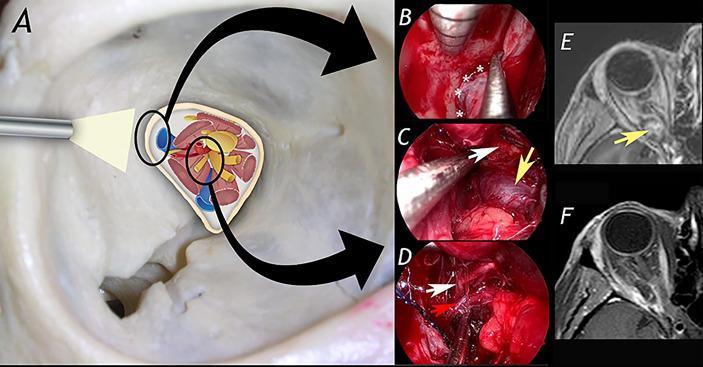
This composite educational image illustrates a transorbital endoscopic-assisted surgical approach for the resection of an orbital apex cavernous hemangioma. Panel A provides a schematic diagram of the orbital apex anatomy, detailing neurovascular structures including the optic nerve, oculomotor nerve branches, and the ophthalmic artery. Panels B, C, and D are intraoperative endoscopic photographs capturing key surgical steps: (B) exposure of the lateral aspect of the superior orbital fissure (indicated by asterisks), (C) identification of the cavernous hemangioma (yellow arrow), and (D) microsurgical dissection of the lesion from the superior division of the oculomotor nerve (white arrow) and the ophthalmic artery (red arrow). Panels E and F present axial T1-weighted MRI scans for comparison: (E) shows the preoperative state with a well-defined mass in the orbital apex compressing adjacent structures, while (F) demonstrates the postoperative result with complete lesion resection and restoration of the orbital apex space. The material is intended for neurosurgical and ophthalmological education, focusing on minimally invasive skull base techniques.
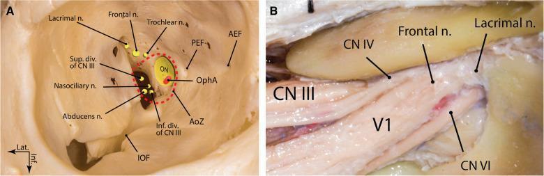
Anatomical diagrams and clinical photographs illustrating the neurovascular structures of the right superior orbital fissure (SOF). Image A provides a frontal schematic view of the bony orbit, highlighting the annulus of Zinn (AoZ) encircling the optic nerve (ON) and ophthalmic artery (OphA). It shows the spatial arrangement of the cranial nerves: the superior and inferior divisions of CN III, the nasociliary nerve, and the abducens nerve (CN VI) are positioned within the annulus. The lacrimal, frontal, and trochlear (CN IV) nerves are shown superior and lateral to the annulus within the fissure. Bony landmarks include the anterior and posterior ethmoidal foramina (AEF, PEF) and the inferior orbital fissure (IOF). Image B is a cadaveric dissection showing the neural anatomy. It depicts the physical relationships between the larger bundles of the oculomotor nerve (CN III), trochlear nerve (CN IV), and the ophthalmic division of the trigeminal nerve (V1) with its frontal and lacrimal branches, alongside the abducens nerve (CN VI) as they converge toward the SOF. This educational material focuses on orbital apex anatomy and the complex arrangement of nerves essential for neurosurgery and ophthalmology.
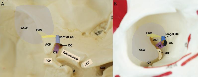
This educational anatomical diagram consists of two panels (A and B) illustrating the bony anatomy and supporting structures of the anterior clinoid process (ACP) within the human skull base. Panel A provides a left oblique intracranial view, identifying the three roots of the ACP: the lateral root connecting to the lesser wing of the sphenoid (LSW, yellow), the anterior root forming the roof of the optic canal (OC, blue), and the posterior root known as the optic strut (OS, purple). Surrounding landmarks include the greater wing of the sphenoid (GSW), posterior clinoid process (PCP), superior orbital fissure (SOF), and the tuberculum sellae. Panel B displays a right intra-orbital view, showing the same colored structures from an endoscopic perspective. This panel highlights the spatial relationship between the ACP, the optic canal, and the superior and inferior orbital fissures (IOF). The gray shaded area represents the planned craniotomy for an endoscopic transorbital approach (ETOA). The visual serves to define critical landmarks for neurosurgical procedures like anterior clinoidectomy.
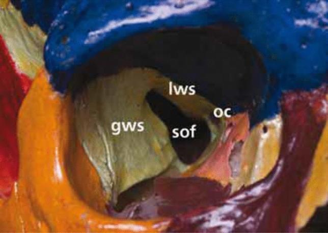
A clinical photograph of an anatomical skull model focused on the right orbital apex, highlighting the complex bony architecture. The sphenoid bone is central to the anatomy, with labels identifying the optic canal (OC), superior orbital fissure (SOF), greater wing of the sphenoid (GWS), and lesser wing of the sphenoid (LWS). The optic canal (OC) is situated medially, bordered superiorly by the LWS and medially by the sphenoid body. The superior orbital fissure (SOF) is a larger, more lateral cleft-like opening located inferolateral to the optic canal, separated from it by the optic strut. The boundaries of the SOF include the LWS superiorly and medially, and the GWS forming the lateral margin. The different bones are color-coded to differentiate cranial structures, with the orbital roof in blue and the lateral orbital wall in orange/yellow. This image serves as an educational tool for medical students and clinicians to understand the spatial orientation of neurovascular conduits at the orbital apex, which are critical in ophthalmology, neurosurgery, and maxillofacial surgery.
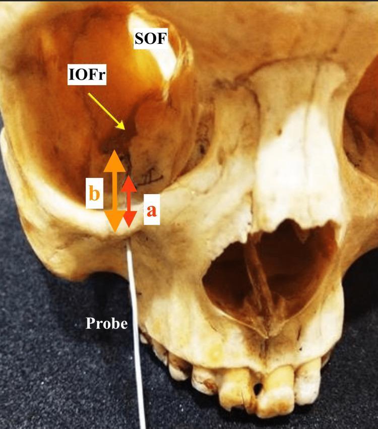
Anatomical anatomical illustration and clinical photograph of a human dry skull focusing on the right infraorbital and orbital regions for morphometric study. A metallic linear probe is inserted into the right infraorbital foramen, demonstrating the trajectory of the infraorbital canal. Key landmarks are labeled: the Superior Orbital Fissure (SOF) and the Inferior Orbital Fissure (IOFr). Two vertical measurement indicators are shown relative to the inferior orbital rim: arrow 'a' represents the distance from the rim to the anterior part of the infraorbital groove, and arrow 'b' represents the distance to the anterior-most extent of the inferior orbital fissure. These measurements help define the clinical anatomy of the infraorbital canal, which is vital for safe anesthetic nerve blocks and maxillofacial surgical procedures. Visible adjacent structures include the nasal cavity, the maxillary sinus region, and the superior alveolar process with maxillary teeth.
superior orbital fissure syndrome cranial nerves III IV VI V1 ophthalmoplegia
Anatomical diagrams and clinical photographs illustrating the neurovascular structures of the right superior orbital fissure (SOF). Image A provides a frontal schematic view of the bony orbit, highlighting the annulus of Zinn (AoZ) encircling the optic nerve (ON) and ophthalmic artery (OphA). It shows the spatial arrangement of the cranial nerves: the superior and inferior divisions of CN III, the nasociliary nerve, and the abducens nerve (CN VI) are positioned within the annulus. The lacrimal, frontal, and trochlear (CN IV) nerves are shown superior and lateral to the annulus within the fissure. Bony landmarks include the anterior and posterior ethmoidal foramina (AEF, PEF) and the inferior orbital fissure (IOF). Image B is a cadaveric dissection showing the neural anatomy. It depicts the physical relationships between the larger bundles of the oculomotor nerve (CN III), trochlear nerve (CN IV), and the ophthalmic division of the trigeminal nerve (V1) with its frontal and lacrimal branches, alongside the abducens nerve (CN VI) as they converge toward the SOF. This educational material focuses on orbital apex anatomy and the complex arrangement of nerves essential for neurosurgery and ophthalmology.
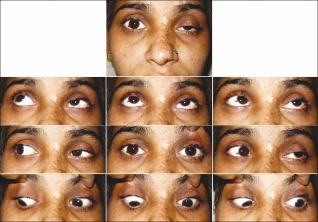
A composite clinical photograph illustrating ophthalmoplegia and ptosis in a patient with Herpes Zoster Ophthalmicus (HZO) and Orbital Apex Syndrome. The top panel shows a primary position view with significant left-sided blepharoptosis. The subsequent nine-gaze montage demonstrates a comprehensive ocular motility assessment. Findings include severe restriction of the left eye in all cardinal directions of gaze (superior, inferior, lateral, and medial), indicating multiple cranial nerve involvement (III, IV, and VI). The right eye shows normal range of motion. The skin of the left forehead and periocular region shows signs of resolving vesiculopustular lesions and post-inflammatory pigmentary changes, characteristic of the ophthalmic division of the trigeminal nerve (V1) involvement. This educational visual represents the clinical presentation of orbital apex syndrome, highlighting the functional deficits in extraocular muscles and eyelid elevation following viral infection in an immunocompromised context.
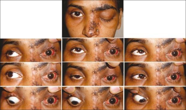
Clinical photograph series documenting a patient with Herpes Zoster Ophthalmicus (HZO) and associated complications. The primary image displays a unilateral vesiculopustular rash and hemorrhagic crusting following the V1 ophthalmic distribution of the trigeminal nerve on the left side, involving the forehead, periocular region, and bridge of the nose (Hutchinson's sign). Marked ophthalmological findings in the left eye include severe ptosis and conjunctival hyperemia. Below, a nine-gaze montage demonstrates a complete limitation of ocular motility (ophthalmoplegia) in the left eye across all cardinal directions of gaze, while the right eye shows normal motility. The clinical presentation is highly suggestive of Orbital Apex Syndrome, characterized by the involvement of cranial nerves III, IV, VI, and the ophthalmic branch of V. This visual material is used in medical education to illustrate the dermatological manifestations of HZO and the neuro-ophthalmological complications associated with viral reactivation in immunocompromised states.
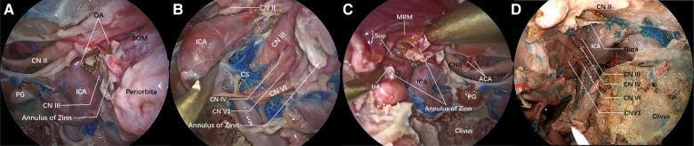
This composite of four endoscopic clinical photographs (A–D) provides an endonasal perspective of the sphenoid sinus lateral wall, specifically focusing on the anatomical landmarks of the optic strut triangle and the cavernous sinus (CS). Panel A demonstrates the relationship between the optic nerve (CN II), the internal carotid artery (ICA), and the ophthalmic artery (OA) following bone removal of the optic strut. Panel B illustrates the vertical spatial arrangement of cranial nerves emerging from the medial wall of the cavernous sinus: from superior to inferior, the oculomotor nerve (CN III), trochlear nerve (CN IV), ophthalmic nerve (CN V1), and abducent nerve (CN VI) are identified. Panel C shows the division of the oculomotor nerve into superior (Sup) and inferior (Inf) branches near the medial rectus muscle (MRM) and Annulus of Zinn. Panel D provides a broader view of the parasellar region, highlighting the course of CN III, IV, VI, and V1 relative to the ICA, clivus, and surrounding dura. These images illustrate key neurovascular relationships critical for transnasal endoscopic decompression of the orbital apex and superior orbital fissure.
Superior Orbital Fissure (SOF) - Complete Exam Guide
1. What Is It?
2. Boundaries (How the Gap Is Formed)
| Border | Structure |
|---|---|
| Above (superior) | Lesser wing of sphenoid |
| Below (inferior) | Greater wing of sphenoid |
| Medially | Body of sphenoid |
| Laterally | Frontal bone (at frontosphenoidal suture) |
Think of it as the gap created where the lesser wing sits above and the greater wing sits below the sphenoid bone.
3. Key Landmark - The Annulus of Zinn
| Compartment | Position | Structures |
|---|---|---|
| Within Annulus (medial/central zone) | Inside the ring | CN III (superior & inferior divisions), CN VI (abducens), Nasociliary nerve (V1 branch) |
| Outside Annulus (lateral zone) | Outside the ring | CN IV (trochlear), Lacrimal nerve (V1), Frontal nerve (V1), Superior ophthalmic vein |
4. Structures Passing Through - The Most Important List
Nerves (6 nerves or nerve branches):
| Nerve | Function |
|---|---|
| CN III - Oculomotor (superior + inferior divisions) | Moves eyeball (SR, IO, MR, IR), elevates upper eyelid, pupil constriction |
| CN IV - Trochlear | Moves superior oblique muscle (intorsion + depression) |
| CN VI - Abducens | Moves lateral rectus muscle (abduction) |
| V1 - Lacrimal branch | Sensory to lacrimal gland, lateral upper lid |
| V1 - Frontal branch | Sensory to forehead (divides into supraorbital + supratrochlear) |
| V1 - Nasociliary branch | Sensory to nasal mucosa, globe, skin of nose tip |
Veins:
- Superior ophthalmic vein (drains to cavernous sinus)
- Inferior ophthalmic vein (partial/occasional)
Artery:
- Orbital branch of middle meningeal artery
- Recurrent branch of lacrimal artery
Memory trick for nerves: "Lazy French Tarts Never Arrive In All Night Cinemas" L=Lacrimal, F=Frontal, T=Trochlear (CN IV), N=Nasociliary, A=Abducens (CN VI), I=Inferior div CN III, A=Above (Superior div CN III) → simplified: "3, 4, 6, V1 branches"
5. Exam Diagrams from Standard Textbooks
Diagram 1: Openings into the Bony Orbit (Gray's Anatomy)
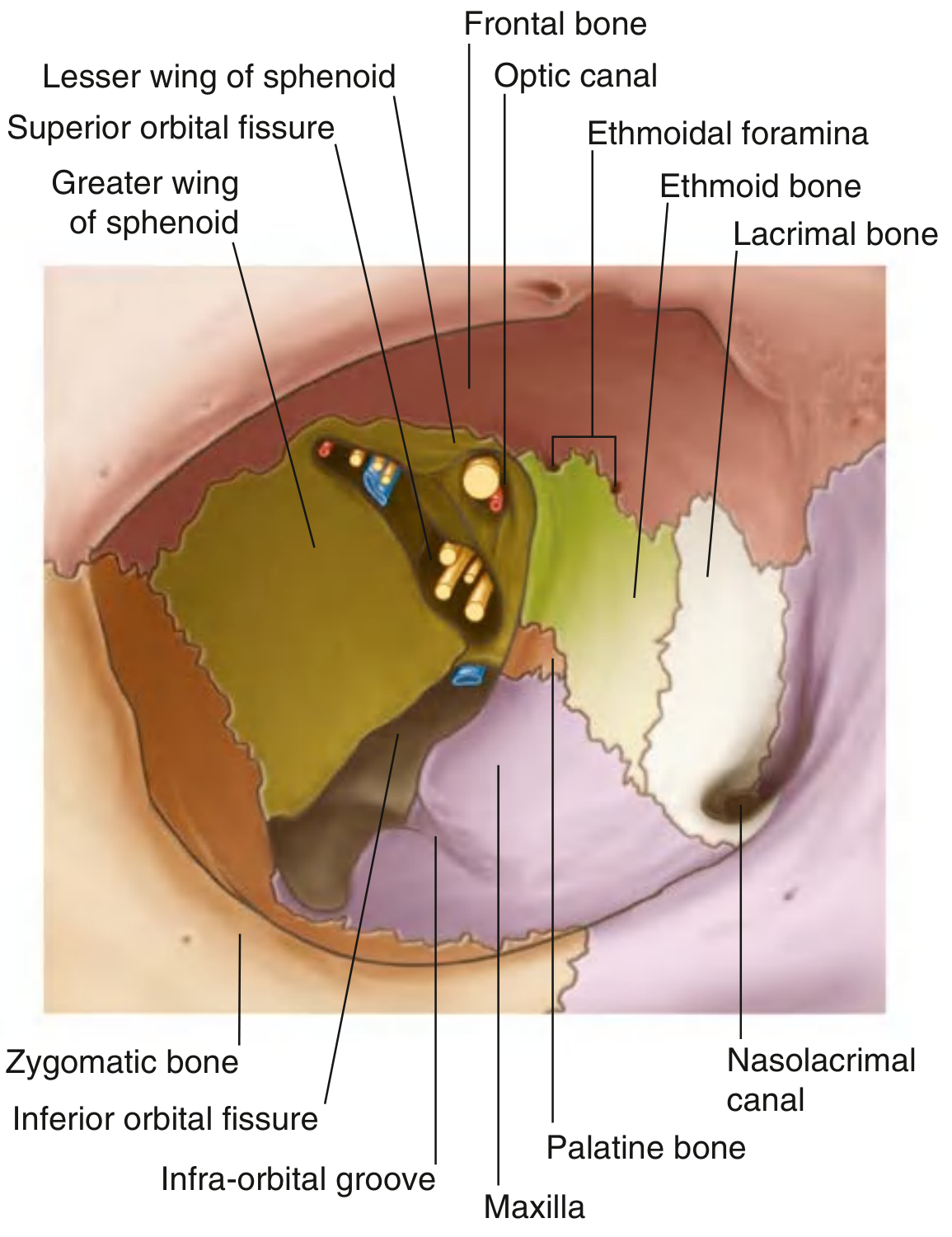
Diagram 2: Cross-Section View of SOF Contents (Most Important Exam Diagram!)
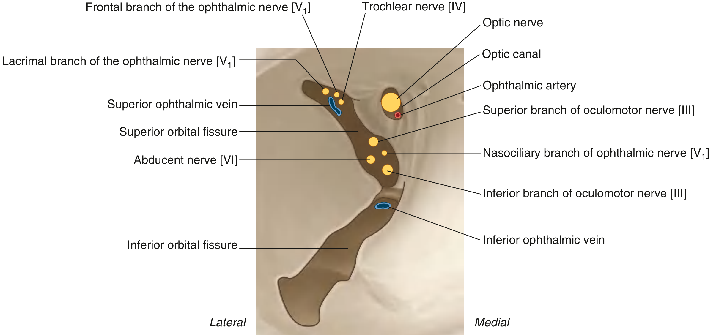
Diagram 3: Skull Specimen showing SOF, Optic Canal, and Key Bony Landmarks
Diagram 4: Cadaveric + Schematic showing the Annulus of Zinn arrangement
6. Superior Orbital Fissure Syndrome
Causes:
- Tumors (meningioma, nasopharyngeal carcinoma, metastases, pituitary adenoma)
- Sphenoid sinusitis
- Trauma (bone fragment compression)
- Aneurysm (internal carotid / posterior communicating artery)
- Cavernous sinus thrombosis
- Tolosa-Hunt syndrome (granulomatous inflammation)
Features:
| Structure Damaged | Clinical Sign |
|---|---|
| CN III (superior div.) | Ptosis (levator palpebrae), SR muscle palsy |
| CN III (inferior div.) | MR, IR, IO palsy; dilated fixed pupil |
| CN IV | Weakness of superior oblique (diplopia on downward gaze) |
| CN VI | Inability to abduct eye (lateral rectus palsy) |
| V1 - all branches | Pain, paresthesia, sensory loss in forehead, nose tip, cornea |
| Superior ophthalmic vein blocked | Proptosis (exophthalmos) |
Key differentiator from Orbital Apex Syndrome: Orbital apex syndrome also damages CN II (optic nerve) → vision loss is added. SOF syndrome alone = NO vision loss.
7. Comparison: SOF Syndrome vs Orbital Apex Syndrome vs Cavernous Sinus Syndrome
| Feature | SOF Syndrome | Orbital Apex Syndrome | Cavernous Sinus Syndrome |
|---|---|---|---|
| CN III | Yes | Yes | Yes |
| CN IV | Yes | Yes | Yes |
| CN VI | Yes | Yes | Yes |
| V1 | Yes | Yes | Yes |
| V2 | No | No | Yes (may be involved) |
| CN II (Vision) | No | Yes (vision loss) | No |
| Proptosis | Possible | Possible | Possible |
| Cause location | SOF itself | SOF + optic canal | Cavernous sinus |
8. Relations to Remember
- SOF is directly continuous with the cavernous sinus posteriorly - this is why cavernous sinus pathology can mimic SOF syndrome
- The inferior ophthalmic vein may also pass through the SOF (it primarily drains via the inferior orbital fissure to the pterygoid plexus, but communicates with SOF/cavernous sinus)
- The sympathetic fibers traveling with CN V1 into the orbit pass through the SOF → involvement causes oculosympathetic paresis (partial Horner's: ptosis + miosis, but NO anhidrosis because the sudomotor fibers travel with external carotid, not through SOF)
9. Quick Exam Summary Box
SUPERIOR ORBITAL FISSURE
━━━━━━━━━━━━━━━━━━━━━━━━
Location:   Between roof + lateral wall of orbit
Shape:      Triangular gap / cleft
Connects:   Orbit ←→ Middle Cranial Fossa
Bounded by: Lesser wing (above) + Greater wing (below) of sphenoid

CONTENTS (mnemonic: 3, 4, 6 + V1 branches + Veins):
  NERVES: CN III (sup + inf), CN IV, CN VI,
          V1 branches (lacrimal, frontal, nasociliary)
  VEINS:  Superior ophthalmic vein
  ARTERY: Orbital br. of middle meningeal a., recurrent lacrimal br.

ANNULUS OF ZINN divides SOF:
  Inside ring  → CN III (both divs), CN VI, Nasociliary nerve
  Outside ring → CN IV, Lacrimal, Frontal nerves, Sup. ophthalmic vein

SOF SYNDROME:
  = Ophthalmoplegia + Ptosis + Fixed dilated pupil
    + V1 sensory loss + Proptosis
  = NO vision loss (CN II spared)