Function of golgi tendon organ

Reading File
Searching Images

Golgi tendon organ diagram anatomy function
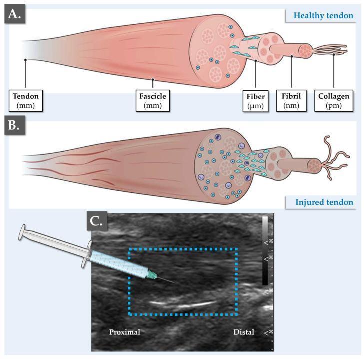
A multi-panel medical graphic illustrating tendon anatomy, pathophysiology, and clinical management. Panel (A) provides an anatomical diagram of a healthy tendon, detailing the hierarchical structure from the whole tendon (mm scale) down to fascicles, fibers (µm), fibrils (nm), and collagen (pm). It shows parallel, organized collagen bundles and sparse, spindle-shaped tenocytes. Panel (B) is a comparison chart showing an injured tendon characterized by disorganization of the extracellular matrix (ECM), collagen denaturing, hypercellularity with rounded cell morphology, and increased presence of immune cells and vascular infiltration. Panel (C) contains a diagnostic ultrasound image of a fissured Achilles tendon in the longitudinal plane. Within a blue dashed box, a linear hypoechoic (dark) area represents the structural fissure, contrasting with the normal hyperechoic fibrillar pattern of a healthy tendon. An overlaid illustration shows a needle delivering a platelet-rich plasma (PRP) injection directly into the fissured site for regenerative therapy. Labels identify proximal and distal orientations, highlighting the clinical application of orthobiologics in managing tendinopathies.
A multi-panel medical graphic illustrating tendon anatomy, pathophysiology, and clinical management. Panel (A) provides an anatomical diagram of a healthy tendon, detailing the hierarchical structure from the whole tendon (mm scale) down to fascicles, fibers (µm), fibrils (nm), and collagen (pm). It shows parallel, organized collagen bundles and sparse, spindle-shaped tenocytes. Panel (B) is a comparison chart showing an injured tendon characterized by disorganization of the extracellular matrix (ECM), collagen denaturing, hypercellularity with rounded cell morphology, and increased presence of immune cells and vascular infiltration. Panel (C) contains a diagnostic ultrasound image of a fissured Achilles tendon in the longitudinal plane. Within a blue dashed box, a linear hypoechoic (dark) area represents the structural fissure, contrasting with the normal hyperechoic fibrillar pattern of a healthy tendon. An overlaid illustration shows a needle delivering a platelet-rich plasma (PRP) injection directly into the fissured site for regenerative therapy. Labels identify proximal and distal orientations, highlighting the clinical application of orthobiologics in managing tendinopathies.

This medical illustration presents two side-by-side axial diagrams of the lateral ankle, contrasting normal anatomy with peroneal tendon subluxation. Both frames detail the lateral malleolus with its characteristic trabecular bone pattern and smooth outer cortex. The left frame illustrates the normal anatomy of the superior peroneal tunnel, where the peroneal tendons (specifically the peroneus longus) are securely positioned in the retromalleolar groove behind the lateral malleolus, stabilized by an intact superior peroneal retinaculum (SPR). The right frame demonstrates a pathological subluxation/dislocation, showing the peroneal tendon displaced anteriorly over the lateral malleolus due to a failure or disruption of the SPR. This comparison serves as an educational tool for orthopedics and sports medicine, highlighting the biomechanical importance of the retinaculum in preventing tendon instability. The diagram is relevant for understanding acute ankle injuries, chronic tendon instability, and the rationale for surgical interventions like retinacular repair or groove deepening.
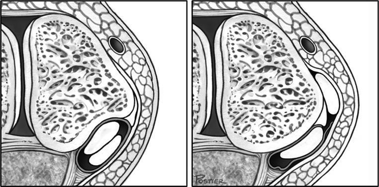
This medical illustration presents two side-by-side axial diagrams of the lateral ankle, contrasting normal anatomy with peroneal tendon subluxation. Both frames detail the lateral malleolus with its characteristic trabecular bone pattern and smooth outer cortex. The left frame illustrates the normal anatomy of the superior peroneal tunnel, where the peroneal tendons (specifically the peroneus longus) are securely positioned in the retromalleolar groove behind the lateral malleolus, stabilized by an intact superior peroneal retinaculum (SPR). The right frame demonstrates a pathological subluxation/dislocation, showing the peroneal tendon displaced anteriorly over the lateral malleolus due to a failure or disruption of the SPR. This comparison serves as an educational tool for orthopedics and sports medicine, highlighting the biomechanical importance of the retinaculum in preventing tendon instability. The diagram is relevant for understanding acute ankle injuries, chronic tendon instability, and the rationale for surgical interventions like retinacular repair or groove deepening.

Anatomical diagram depicting the normal musculoskeletal structure of a human finger digit, specifically focusing on the flexor tendon and its pulley system. The illustration shows a tan-colored cylindrical phalangeal bone as the foundation. Overlaid on the bone and underlying tendon is a series of white, fibrous bands representing the annular (A) and cruciform (C) pulleys. The annular pulleys appear as dense, circular transverse bands (like the A1, A2, and A3 pulleys), while the cruciform pulleys are shown as thinner, crisscrossing diagonal bands that allow for flexibility during finger flexion. A smooth, glistening tendon is visible beneath these ligamentous sheaths. The diagram illustrates the osteofibrous canal, which serves to keep the flexor tendons closely apposed to the bone, preventing 'bowstringing' and facilitating efficient mechanical finger movement. This visual is relevant for understanding hand anatomy, tenosynovitis pathology, and surgical or acupotomy interventions for trigger finger.
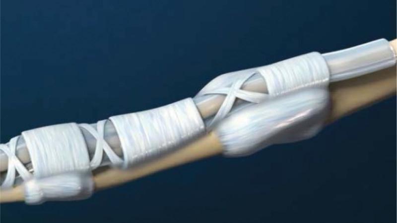
Anatomical diagram depicting the normal musculoskeletal structure of a human finger digit, specifically focusing on the flexor tendon and its pulley system. The illustration shows a tan-colored cylindrical phalangeal bone as the foundation. Overlaid on the bone and underlying tendon is a series of white, fibrous bands representing the annular (A) and cruciform (C) pulleys. The annular pulleys appear as dense, circular transverse bands (like the A1, A2, and A3 pulleys), while the cruciform pulleys are shown as thinner, crisscrossing diagonal bands that allow for flexibility during finger flexion. A smooth, glistening tendon is visible beneath these ligamentous sheaths. The diagram illustrates the osteofibrous canal, which serves to keep the flexor tendons closely apposed to the bone, preventing 'bowstringing' and facilitating efficient mechanical finger movement. This visual is relevant for understanding hand anatomy, tenosynovitis pathology, and surgical or acupotomy interventions for trigger finger.

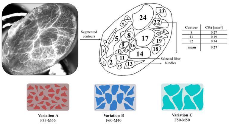
This composite educational illustration demonstrates the bio-inspired design of a Tendon-Mimic (TM) pattern based on equine superficial digital flexor tendon (SDFT) anatomy. The image is divided into three sections: 1) A cross-sectional grayscale stereo-micrograph of a tendon specimen showing the internal hierarchical arrangement of fascicles. 2) A diagnostic line diagram illustrating the segmentation of the specimen into 24 distinct fascicle contours. A corresponding data table provides the cross-sectional area (CSA) in mm² for selected fiber bundles (contours 8, 13, and 22), noting a mean CSA of 0.27 mm². 3) Three colored schematics (Variations A, B, and C) showing different biomimetic fiber-to-matrix ratios for 3D printing applications: F33-M66 (red), F60-M40 (dark blue), and F50-M50 (cyan). The figure illustrates the translation of biological morphology into quantitative parameters for bioengineering and tissue-mimicking polymer research, specifically focusing on tendon fascicle distribution and cross-sectional morphology.
This composite educational illustration demonstrates the bio-inspired design of a Tendon-Mimic (TM) pattern based on equine superficial digital flexor tendon (SDFT) anatomy. The image is divided into three sections: 1) A cross-sectional grayscale stereo-micrograph of a tendon specimen showing the internal hierarchical arrangement of fascicles. 2) A diagnostic line diagram illustrating the segmentation of the specimen into 24 distinct fascicle contours. A corresponding data table provides the cross-sectional area (CSA) in mm² for selected fiber bundles (contours 8, 13, and 22), noting a mean CSA of 0.27 mm². 3) Three colored schematics (Variations A, B, and C) showing different biomimetic fiber-to-matrix ratios for 3D printing applications: F33-M66 (red), F60-M40 (dark blue), and F50-M50 (cyan). The figure illustrates the translation of biological morphology into quantitative parameters for bioengineering and tissue-mimicking polymer research, specifically focusing on tendon fascicle distribution and cross-sectional morphology.

This medical illustration depicts the surgical technique and functional anatomy of a lower trapezius transfer for shoulder reconstruction. The main diagram shows a patient in a lateral decubitus position, demonstrating active external rotation of the arm. Anatomical highlights in red illustrate the lower fibers of the trapezius muscle being utilized as a tendon transfer to restore shoulder function, specifically targeting irreparable rotator cuff tears where external rotation is lost. The muscle is shown transitioning into a graft that extends toward the humerus. An inset at the top provides a detailed view of the surgical fixation method, illustrating a weave-style tendinous anastomosis (likely a Pulvertaft weave) secured with sutures to join the donor tendon to the recipient site. This procedure is indicated for patients with posterosuperior rotator cuff insufficiency, providing a biomechanical advantage for external rotation when the infraspinatus and teres minor are non-functional.
This medical illustration depicts the surgical technique and functional anatomy of a lower trapezius transfer for shoulder reconstruction. The main diagram shows a patient in a lateral decubitus position, demonstrating active external rotation of the arm. Anatomical highlights in red illustrate the lower fibers of the trapezius muscle being utilized as a tendon transfer to restore shoulder function, specifically targeting irreparable rotator cuff tears where external rotation is lost. The muscle is shown transitioning into a graft that extends toward the humerus. An inset at the top provides a detailed view of the surgical fixation method, illustrating a weave-style tendinous anastomosis (likely a Pulvertaft weave) secured with sutures to join the donor tendon to the recipient site. This procedure is indicated for patients with posterosuperior rotator cuff insufficiency, providing a biomechanical advantage for external rotation when the infraspinatus and teres minor are non-functional.

Historical anatomical diagram from Carl Toldt's 'Anatomischer Atlas' depicting a dissection of the human abdominal and pelvic cavity. The illustration focuses on the spatial relationships of the visceral organs and their peritoneal attachments. Key labeled structures include the spleen (Lien), shown as an oblong organ situated superior to the left colic flexure (Flexura coli sinistra) and adjacent to the jejunum. In the upper right quadrant (anatomical left), the left lobe of the liver (Lobus sinister hepatis), ligamentum teres, and gallbladder (Vesica fellea) are prominent. The gastrointestinal tract is shown with the duodenum, ileum, and cecum (Intestinum caecum). Extensive detail is provided on the mesentery and folds, including the Mesenterium commune, Mesocolon descendens, and Mesocolon sigmoideum. In the inferior pelvic region, the ovary (Ovarium) is visible. This diagram illustrates the complex organization of the peritoneum and the fixation of various abdominal organs, which is of historical and educational significance for understanding surgical anatomy and conditions such as 'wandering spleen' (splenoptosis).

Historical anatomical diagram from Carl Toldt's 'Anatomischer Atlas' depicting a dissection of the human abdominal and pelvic cavity. The illustration focuses on the spatial relationships of the visceral organs and their peritoneal attachments. Key labeled structures include the spleen (Lien), shown as an oblong organ situated superior to the left colic flexure (Flexura coli sinistra) and adjacent to the jejunum. In the upper right quadrant (anatomical left), the left lobe of the liver (Lobus sinister hepatis), ligamentum teres, and gallbladder (Vesica fellea) are prominent. The gastrointestinal tract is shown with the duodenum, ileum, and cecum (Intestinum caecum). Extensive detail is provided on the mesentery and folds, including the Mesenterium commune, Mesocolon descendens, and Mesocolon sigmoideum. In the inferior pelvic region, the ovary (Ovarium) is visible. This diagram illustrates the complex organization of the peritoneum and the fixation of various abdominal organs, which is of historical and educational significance for understanding surgical anatomy and conditions such as 'wandering spleen' (splenoptosis).

Finding Sources
Finding Sources
Reading File
Reading File
Reading File
Loading Image
Loading Image
I now have all the information needed for a thorough, well-illustrated answer. Here it is:

Golgi Tendon Organ (GTO) - Structure and Function

Structure
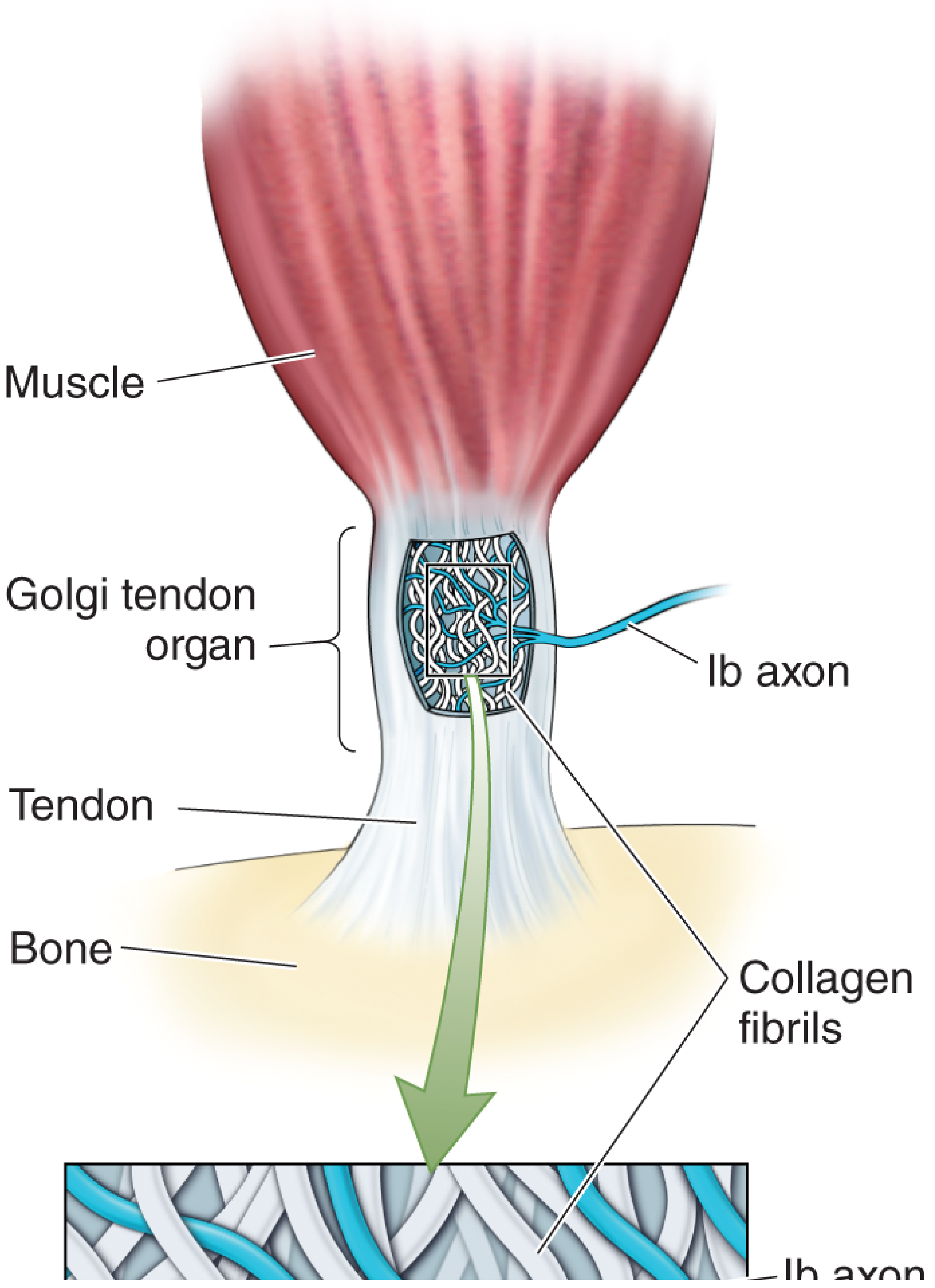
The GTO is an encapsulated sensory receptor located at the musculotendinous junction, arranged in series with the muscle fibers (unlike the muscle spindle, which lies in parallel). Each GTO is connected to roughly 10-15 muscle fibers, and its interior contains a network of collagen fibrils intertwined with the branching terminals of Ib afferent axons (large, myelinated fibers averaging ~16 µm in diameter).
Golgi tendon organ anatomy - collagen fibrils and Ib axon at the musculotendinous junction

Primary Function: Tension Sensing

The GTO acts as a highly sensitive strain gauge for muscle tension (force) - not length. When a muscle contracts or is stretched, the pulling force compresses and distorts the collagen fibrils, mechanically deforming the Ib axon terminals and triggering action potentials.
  • In parallel (muscle spindle): detects muscle length
  • In series (GTO): detects muscle tension / force
This series arrangement means the GTO is especially sensitive during active muscle contraction, since the full contractile force is transmitted through it. It also responds during passive stretch, but less intensely.

Response Characteristics

The GTO has both a dynamic response and a static response:
  • Dynamic: fires intensely when tension suddenly increases
  • Static: settles to a steady firing rate proportional to the sustained muscle tension
This means the nervous system receives real-time, detailed information about the degree of tension in each small segment of a muscle. - Guyton and Hall Textbook of Medical Physiology

The Golgi Tendon Reflex (Ib / Autogenic Inhibition)

This is the GTO's most well-known reflex arc:
Golgi tendon reflex - excess tension triggers Ib afferent, inhibitory interneuron, anterior motor neuron inhibition, and relaxation response
Step-by-step:
  1. Excessive tension in muscle/tendon activates GTO
  2. Ib afferent axons carry signals rapidly to the spinal cord
  3. Ib axons synapse on an inhibitory interneuron in the dorsal horn
  4. The inhibitory interneuron suppresses the alpha motor neuron of the same muscle (autogenic inhibition)
  5. The muscle relaxes - reducing tension and protecting the muscle and tendon from tearing or avulsion
When tension becomes extreme, this inhibition can be so powerful it causes sudden, complete relaxation of the entire muscle - called the lengthening reaction (or "clasp-knife" phenomenon). This is a protective mechanism against musculotendinous damage. - Guyton and Hall, Medical Physiology

Simultaneous Effects on Antagonist Muscles

The Ib afferent simultaneously excites excitatory interneurons targeting the antagonist muscle, causing it to contract. This is the inverse of the stretch reflex. So the overall effect is:
Effect on...Result
Agonist (contracting muscle)Inhibited (relaxed)
AntagonistFacilitated (contracted)

Other Important Functions

Beyond protection, GTOs serve broader roles:
  1. Continuous force monitoring during normal movement: Even at low forces, Ib axons are tonically active, providing the spinal cord and cerebellum detailed force information via spinocerebellar tracts.
  2. Locomotion: During rapid movements like walking or running, GTO input can actually excite motor neurons of the same muscle (opposite of the protective reflex), helping regulate and sustain rhythmic movement patterns. - Medical Physiology (Boron & Boulpaep)
  3. Joint stability: GTO reflex activity helps stabilize specific joints by modulating the tension balance across joint-spanning muscles.
  4. Cerebellar input: Signals travel via dorsal and ventral spinocerebellar tracts to the cerebellum, contributing to fine motor coordination and learning.

Key Comparison: GTO vs. Muscle Spindle

FeatureGolgi Tendon OrganMuscle Spindle
LocationMusculotendinous junctionWithin muscle belly
ArrangementIn series with fibersIn parallel with fibers
DetectsMuscle tension/forceMuscle length
Afferent fiberGroup IbGroup Ia (primary), II (secondary)
Reflex effectInhibits own muscle (autogenic inhibition)Excites own muscle (stretch reflex)
Protective roleAgainst excessive tensionAgainst excessive stretch
Sources: Neuroscience: Exploring the Brain (5th ed.); Guyton and Hall Textbook of Medical Physiology; Medical Physiology (Boron & Boulpaep); Miller's Review of Orthopaedics (9th ed.)
This is a shared conversation. Sign in to Orris to start your own chat.