
Ankle approaches
ankle surgical approaches incision anterolateral anteromedial posterolateral
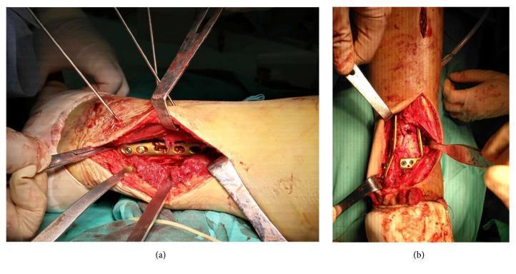
A clinical photograph consisting of two panels (a and b) illustrating orthopedic surgical approaches for the internal fixation of complex ankle fractures. Panel (a) shows a posterolateral approach, with a longitudinal incision on the lateral aspect of the distal leg. Self-retaining and manual retractors expose the deep tissue layers and the posterior column of the tibia. Internal hardware, consisting of a metallic compression plate and fixation screws, is visible, secured to the bone to achieve anatomical reduction. Panel (b) depicts an anterior extensile approach with the patient in a supine position. This view demonstrates the exposure of the anterior articular surface and the distal tibia. Multiple retractors provide visualization of the fracture site, where an anterior rafting plate and screws are being utilized for stabilization. Both images highlight the importance of specific surgical corridors (posterolateral versus anterior) in managing multicomponent pilon or ankle fractures, focusing on soft tissue handling and precise anatomical hardware placement.
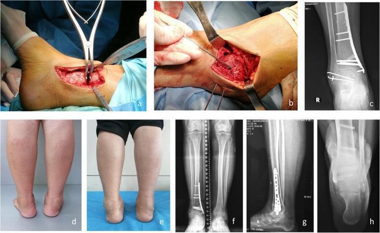
This composite figure illustrates the surgical management and longitudinal follow-up of a patient with varus ankle arthritis. Panels (a) and (b) are intraoperative clinical photographs showing anteromedial and anterolateral surgical approaches for supramalleolar osteotomy and lateral ligament reconstruction. Panel (c) is a 6-week postoperative anteroposterior (AP) radiograph showing Kirschner wire (K-wire) fixation of the talus. Panels (d) and (e) are clinical photographs comparing preoperative and 20-month postoperative hindfoot alignment, demonstrating correction from a varus deformity to a neutral axis. Panels (f), (g), and (h) provide 20-month postoperative weight-bearing imaging, including AP, lateral, and hindfoot alignment radiographs. These diagnostic images reveal a medial distal tibial locking plate and screws fixating the supramalleolar osteotomy site. Key educational concepts shown include the surgical correction of distal tibial alignment, the use of K-wires for temporary talar stabilization, and the objective improvement of joint matching and tibial-talar angles (MDTA, ADTA, TTA) in the context of late-stage ankle arthritis.
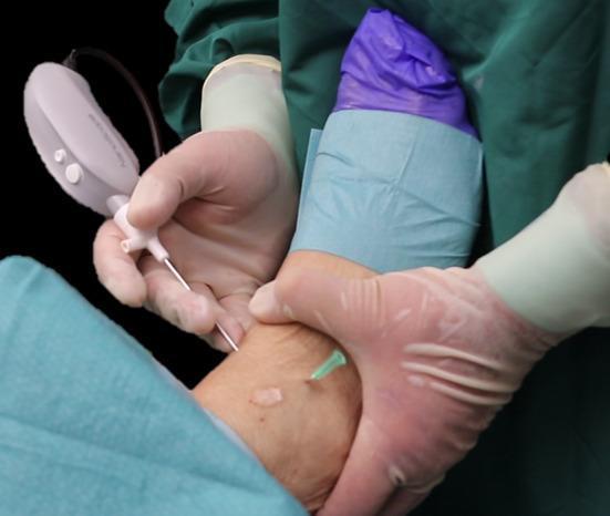
Clinical photograph illustrating the external setup of a minimally invasive ankle arthroscopy. The image shows a surgeon's gloved hands performing the procedure on a prepped ankle joint. A 2-mm diameter arthroscope, attached to a handheld control unit with a white casing, is introduced via the anteromedial portal. A green-hubbed hypodermic needle is inserted laterally to mark and localize the anterolateral portal for secondary instrument access. The surgical site is prepared with an antiseptic solution and isolated using blue sterile drapes, while the distal foot is covered with a purple sterile wrap. The educational focus is on the correct anatomical positioning of standard arthroscopic portals (anteromedial and anterolateral) and the use of small-caliber (2-mm) instrumentation in orthopedic sports medicine. This visualization demonstrates the external coordination required for joint insufflation and instrument triangulation during diagnostic or therapeutic ankle surgery.
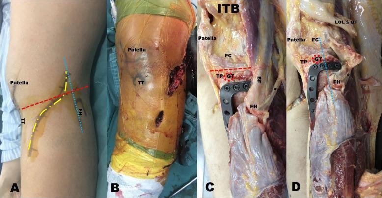
This composite of clinical and anatomical images illustrates a modified anterolateral surgical approach for treating posterolateral tibial plateau fractures. Panel A displays the planned curved incision (yellow dotted line) on the lateral knee, positioned between the tibial tubercle (TT) and the anterior edge of the fibular head (blue dotted line), intersecting the joint line (red dashed line). Panel B shows the actual surgical incision in an intraoperative setting. Panels C and D provide fresh specimen dissections demonstrating the anatomical depth and implant placement. Key structures identified include the femoral condyle (FC), patella, tibial plateau (TP), and Gerdy’s tubercle (GT), which is detached in these views (red dotted circle). The novel reverse L-shaped anatomical plate is shown secured to the posterolateral tibial plateau. Panel D specifically highlights the detachment and retraction of the biceps femoris (BF) and lateral collateral ligament (LCL) to facilitate plate fixation. The images emphasize the plate's ability to provide subchondral support via multiple rafting screws while avoiding extensive posterior dissection near the common peroneal nerve.
Surgical Approaches to the Ankle
1. Anterolateral Approach (to the Ankle and Chopart Joint)
- Begin incision over anterolateral leg, medial to fibula, 5 cm proximal to ankle joint. Extend distally over the joint, anterolateral talar body, and calcaneocuboid joint to the base of the 4th metatarsal (extensible proximally or distally as needed).
- Incise fascia and superior/inferior extensor retinacula down to tibial periosteum and ankle capsule. This divides the anterolateral malleolar and lateral tarsal arteries.
- Identify and protect intermediate dorsal cutaneous branches of the superficial peroneal nerve.
- Divide or reflect extensor digitorum brevis distally.
- Retract extensor tendons, dorsalis pedis artery, and deep peroneal nerve medially; incise capsule.
- Expose talonavicular joint by dissecting deep and incising its capsule transversely.
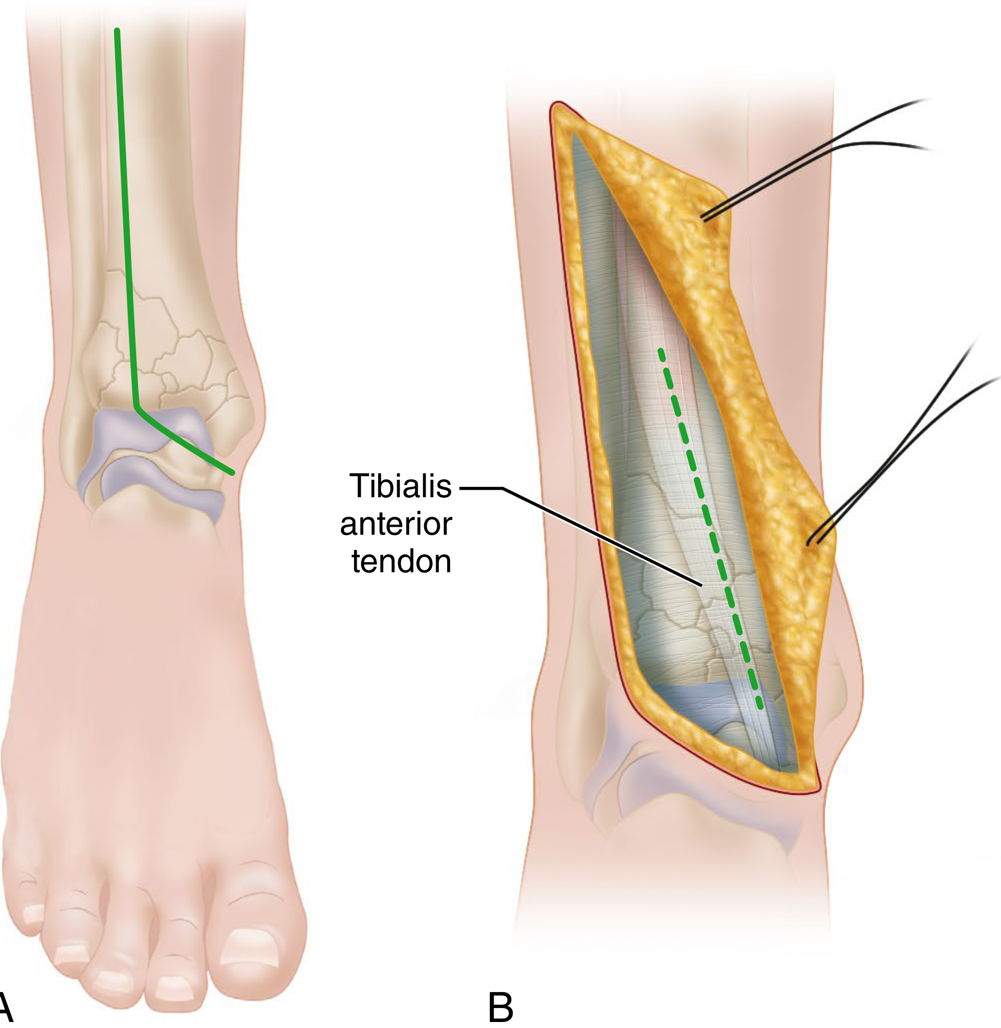
2. Anteromedial (Extensile) Approach
3. Kocher Lateral Approach to the Tarsus and Ankle
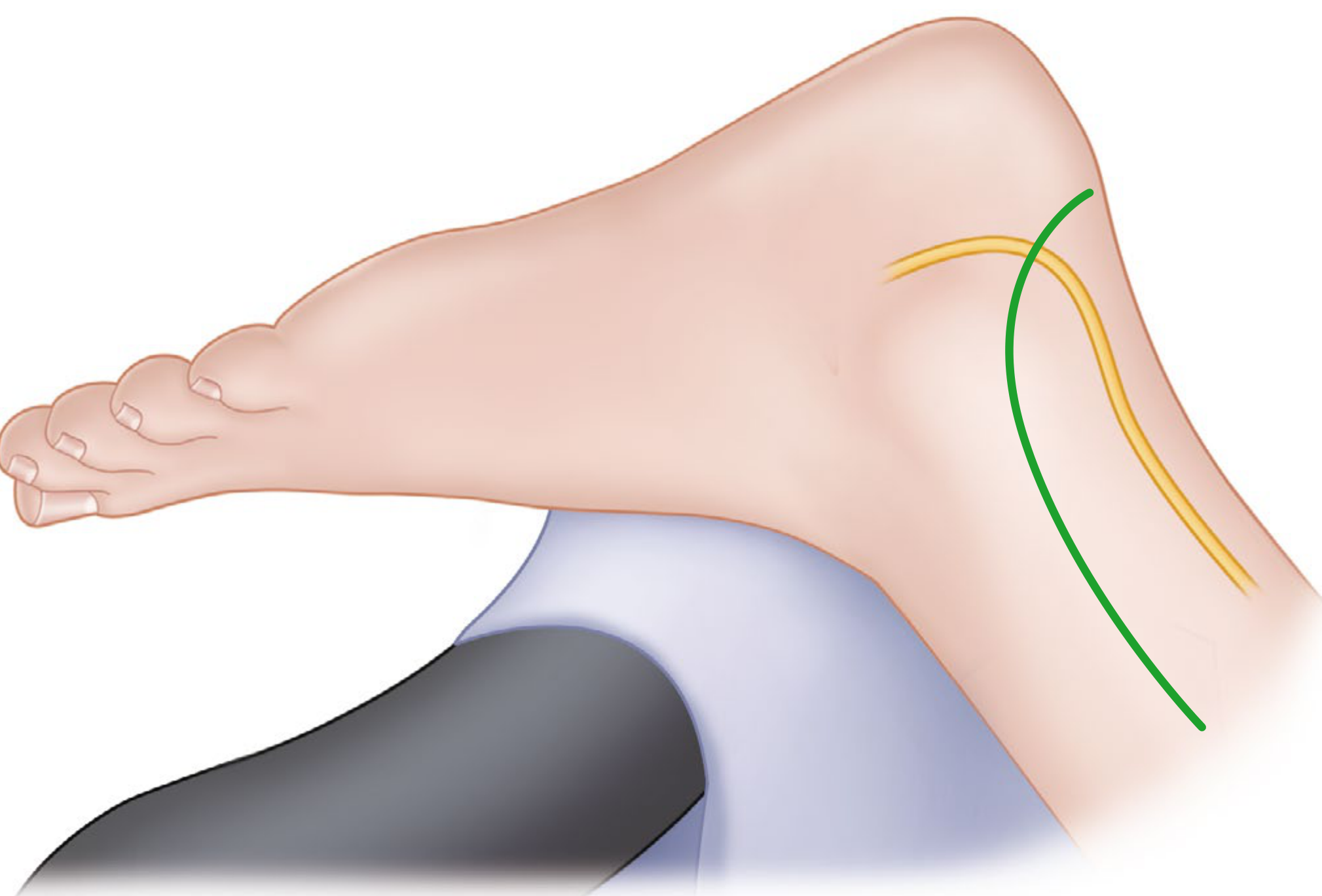
- Incision: from just lateral/distal to the head of the talus, curve 2.5 cm inferior to the tip of the lateral malleolus, then posteriorly and proximally, ending 2.5 cm posterior to the fibula and 5 cm proximal to the malleolar tip.
- Incise fascia, retract peroneal tendons posteriorly, protecting the lesser saphenous vein and sural nerve posterior to the incision.
- If wider field needed: Z-plasty and retract tendons.
- Deepen distally, divide calcaneofibular ligament, expose subtalar joint. Calcaneocuboid and talonavicular joints reachable through distal part.
- After dividing talofibular ligaments, dislocate ankle by medial traction to access entire articular surface.
4. Transfibular Posterolateral Approach (Gatellier and Chastang)
- Large, laterally situated posterior tibial lip (posterior malleolus) fractures
- Osteochondritis dissecans of the lateral talar dome
- Osteochondromatosis of the ankle
- Laterally based total ankle replacement
- Incision along posterior fibular margin, 12 cm proximal to the lateral malleolus tip, extending distally to the tip, then curving anteriorly 2.5-4 cm in the line of the peroneal tendons.
- Expose fibula superperiosteally; incise peroneal retinacular sheaths, displace tendons anteriorly.
- If fibula intact: osteotomize 10 cm proximal to malleolar tip, divide interosseous membrane and tibiofibular ligaments.
- Preserve calcaneofibular and talofibular ligaments as a hinge - turn fibula laterally to expose lateral/posterior distal tibia and lateral ankle joint. (Caution in children: avoid fracturing distal fibular physis.)
- Closure: replace fibula and fix with a transsyndesmotic screw. Overdrill fibula hole for compression. Dorsiflex ankle while tightening (talar dome wider anteriorly).
5. Posterior Approach to the Ankle
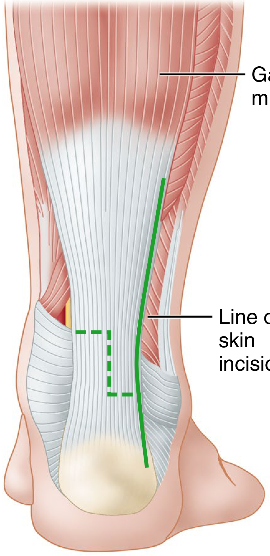
- Patient prone.
- 12 cm incision along posterolateral border of the Achilles tendon down to calcaneal insertion.
- Divide superficial and deep fasciae; divide Achilles tendon by Z-plasty or retract it; incise posterior capsule.
- Structures at risk: posterior tibial artery and tibial nerve (medial), sural nerve (lateral).
6. Posteromedial Approach Through Posterior Tibial Tendon Sheath (Bassett et al.)
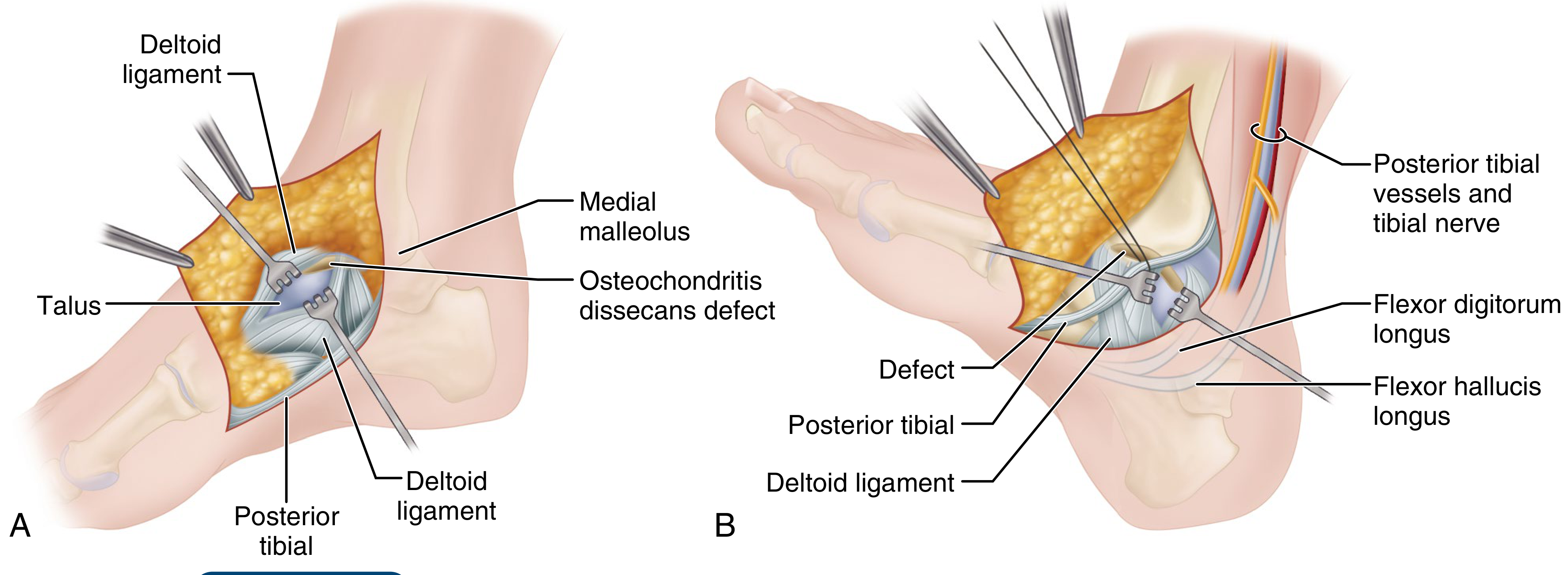
- Patient prone (posteromedial access) or supine with hip/knee flexed and externally rotated.
- Palpate medial malleolus and Achilles tendon.
- 5-8 cm incision overlying the posterior tibial tendon behind the medial malleolus, curving distally and slightly anteriorly following the malleolar contour.
- Open posterior tibial tendon sheath; protect posterior tibial vessels and tibial nerve, FDL, and FHL.
7. Transverse Incision Medial Approach (Koenig and Schaefer)
- Fracture-dislocations of the talus
- Other traumatic lesions of the ankle
- Osteochondritis dissecans of the medial talar dome
- Curved incision just proximal to medial malleolus; divide malleolus with osteotome or power saw, preserving the deltoid ligament attachment.
- Subluxate talus and malleolus laterally to access joint surfaces.
- Pre-drill screw holes before osteotomy (to aid replacement). Fix with two screws (prevents rotation of osteotomized fragment) using interfragmentary compression technique.
8. Medial Approach to the Posterior Tibia (Broomhead / Colonna-Ralston)
Summary Table
| Approach | Incision | Key Structures Exposed | At Risk | Main Indications |
|---|---|---|---|---|
| Anterolateral | Anteromedial to fibula → 4th MT base | Ankle, talus, most tarsals, Chopart | Superficial peroneal n., dorsalis pedis | Pilon Fx, triple/pantalar arthrodesis |
| Anteromedial (extensile) | Lateral to TA tendon → medial malleolus | Anterior ankle, distal tibia | TA tendon, ATA | High-energy pilon |
| Kocher lateral | Below/behind lateral malleolus | Subtalar, midtarsal, ankle | Sural n., lesser saphenous v. | Talectomy, lateral joint access |
| Transfibular posterolateral | Posterior fibula → anterior curve | Lateral/posterior tibia, lateral ankle | Peroneal tendons, fibular physis (children) | Posterior malleolus Fx, OCD lateral talus |
| Posterior | Along posterolateral Achilles | Posterior ankle joint | Posterior tibial a./n., sural n. | Posterior ankle fusion |
| Posteromedial (Bassett) | Behind medial malleolus | Posterior talar dome, posterior capsule | Post tibial vessels/nerve, FDL, FHL | OCD medial talus, posterior joint |
| Transverse medial (Koenig-Schaefer) | Transverse above medial malleolus + osteotomy | Medial talar dome | Post tibial vessels/nerve | OCD medial talus, fracture-dislocation |
| Medial (Broomhead) | Between post. tibia and Achilles | Posterior/medial malleolus | Post tibial vessels/nerve, FDL, FHL | Posterior malleolus Fx |
Supinator muscle
supinator muscle anatomy origin insertion posterior interosseous nerve radial nerve
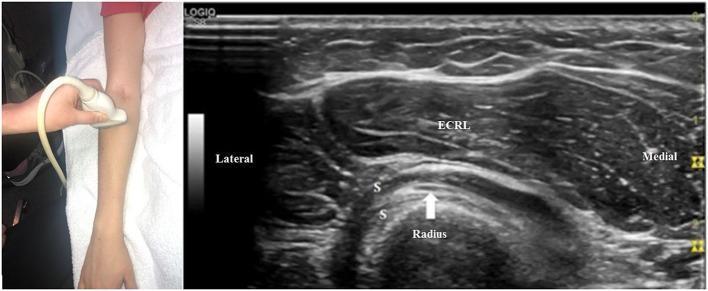
This composite image includes a clinical photograph showing ultrasound transducer placement on the proximal dorsal forearm and a corresponding cross-sectional diagnostic ultrasound image of the radial nerve anatomy. The ultrasound demonstrates the deep motor branch of the radial nerve, identified here as the posterior interosseous nerve (PIN), indicated by a white arrow. The PIN is visualized as a small, oval, hypoechoic structure with a fascicular pattern, coursing obliquely within the supinator muscle (labeled 'S'). The nerve is positioned between the superficial and deep heads of the supinator. Deep to the supinator is the radius, appearing as a prominent, convex, hyperechoic bony surface with posterior acoustic shadowing. Superficial to the supinator muscle is the extensor carpi radialis longus (ECRL), showing a characteristic pennate fibrillar echotexture. Lateral and medial orientations are labeled on the image. This imaging is clinically significant for evaluating nerve entrapment syndromes, such as radial tunnel syndrome or posterior interosseous nerve syndrome at the arcade of Frohse.
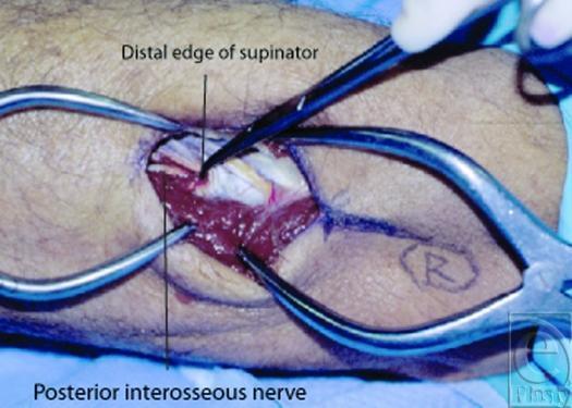
Clinical photograph showing a surgical dissection of the posterior forearm to demonstrate anatomical landmarks relevant to radial nerve compression. The image features a vertical incision retracted by metallic surgical instruments to reveal deep musculoskeletal structures. The supinator muscle is visible as a dark red, striated tissue mass in the center of the field. A black pointer identifies the 'Distal edge of supinator,' which exhibits a whitish-yellow, fibrous texture. Deep to this fibrous margin, the posterior interosseous nerve (PIN) is identified as it exits the supinator muscle. This anatomical view is critical for understanding surgical decompression sites for radial tunnel syndrome and PIN syndrome, highlighting the relationship between the distal supinator fascia and the exiting motor branch of the radial nerve.
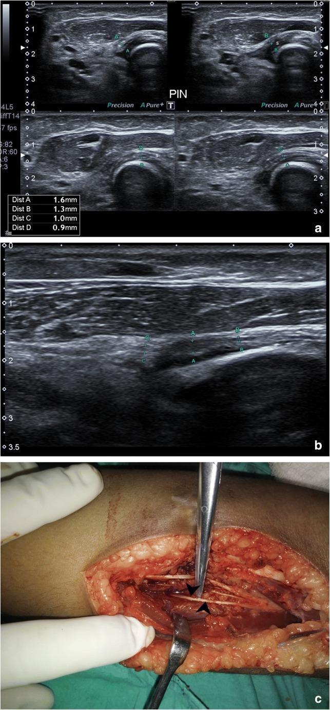
This composite educational resource illustrates the diagnostic evaluation and surgical management of posterior interosseous nerve (PIN) entrapment at the elbow. Figure (a) consists of high-resolution ultrasound frames showing the PIN in cross-section as it winds around the radial head and enters between the two heads of the supinator muscle (s). These frames demonstrate a normal nerve calibre (ranging from 0.9mm to 1.6mm) and typical speckled echogenicity. Figure (b) provides a longitudinal ultrasound view of the PIN distal to the supinator entry, showing focal thickening (calibre increase) and pathological hypo-echogenicity at point 'A', indicative of entrapment neuropathy or a pseudoneuroma. Figure (c) is a clinical photograph of the intraoperative field, showing the PIN (indicated by arrowheads) after surgical neurolysis and release from surrounding fibrous scar tissue at the radial neck. The content is suitable for orthopedic and radiology education, focusing on upper limb peripheral nerve anatomy, ultrasonography of nerve entrapment syndromes, and surgical decompression.
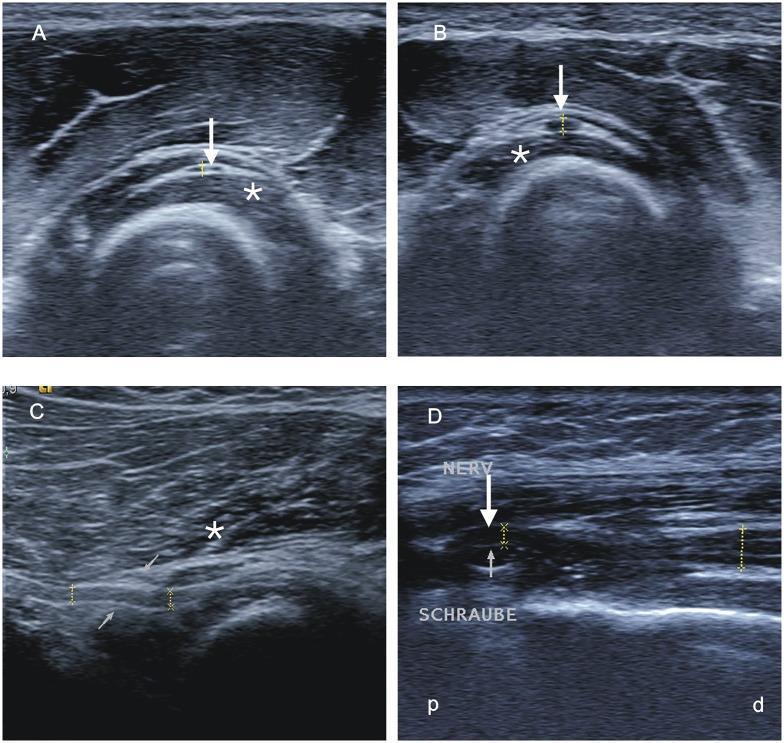
High-resolution sonographic diagnostic images illustrating radial nerve pathology. (A, B) Transverse ultrasound views compare the posterior interosseous nerve (PIN) within the supinator muscle (asterisk). Image A shows normal nerve morphology (arrow) on the healthy side, while Image B demonstrates significant hypoechoic swelling and increased cross-sectional area of the PIN on the affected side, indicating a proximal lesion. (C) Longitudinal ultrasound view shows the PIN with focal caliber change and swelling prior to its entry into the Arcade of Frohse (thin arrows) and as it passes through the supinator muscle (asterisk). (D) Longitudinal ultrasound of the distal upper arm shows the radial nerve (NERV) being compressed by a hyperechoic metallic osteosynthesis screw (SCHRAUBE), resulting in a visible focal indentation and nerve displacement (arrow). These images serve as educational materials for identifying nerve entrapment, post-surgical complications, and sonographic markers of peripheral neuropathy such as nerve edema and mechanical impingement.
Supinator Muscle
Overview
Origin, Insertion, Innervation, Function
| Details | |
|---|---|
| Origin - Superficial layer | Lateral epicondyle of humerus, radial collateral ligament, annular ligament |
| Origin - Deep layer | Supinator crest of the ulna |
| Insertion | Lateral surface of radius superior to the anterior oblique line (anterior and lateral walls of the proximal third of the radius) |
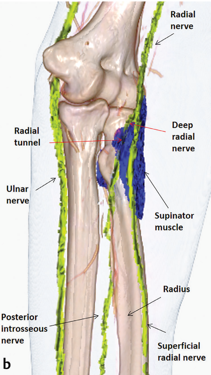
| Innervation | Posterior interosseous nerve (deep branch of radial nerve) - C6, C7 |
| Action | Supination of the forearm |
Anatomy of the Two Layers
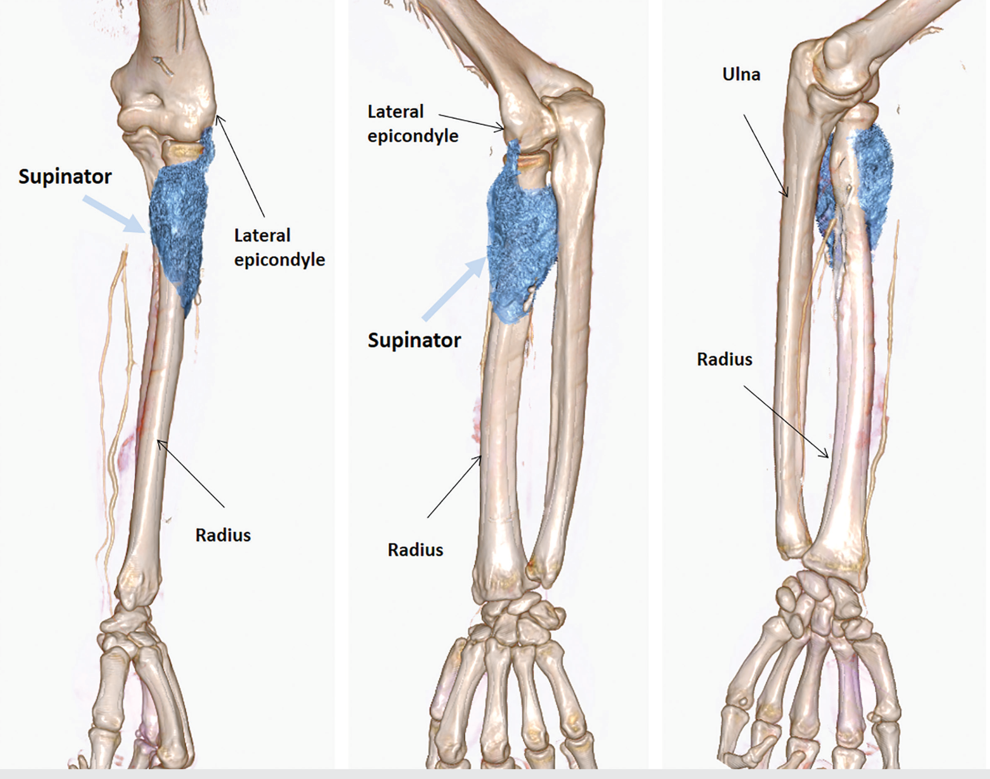
- The superficial layer arises from the lateral epicondyle, radial collateral ligament, and annular ligament.
- The deep layer arises from the supinator crest of the ulna.
The Arcade of Frohse - Key Surgical Landmark
Clinical Relevance
1. Radial Tunnel Syndrome
- At the fibrous lateral edge of the ECRB tendon
- Radial recurrent vessels (leash of Henry)
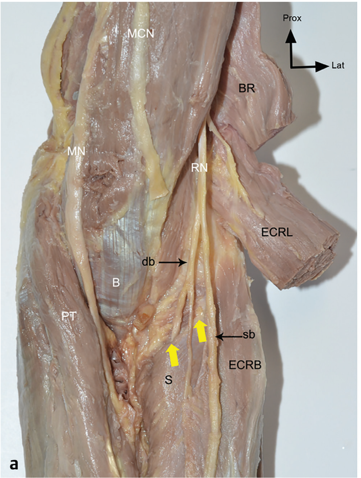
- The arcade of Frohse (most common) - proximal fibrous edge of superficial head
- Within the substance of the supinator (supinator channel syndrome)
- At the distal border of the supinator as the nerve exits
2. Posterolateral Approach to the Proximal Radius (Thompson)
Summary
- Two heads: superficial (lateral epicondyle + ligaments) and deep (supinator crest of ulna)
- Wraps around the proximal third of the radius
- Action: Supination (works at all speeds; biceps assists only with rapid supination or against resistance)
- Nerve: Posterior interosseous nerve (C6, C7) passes through it via the arcade of Frohse
- Surgical hazard: PIN is at risk during posterolateral approaches to the proximal radius - keep forearm pronated to maximally displace the nerve away from the radial neck