
5 mark answer for horizontally unfavorable mandibular angle fracture
horizontally unfavorable mandibular angle fracture diagram muscle pull
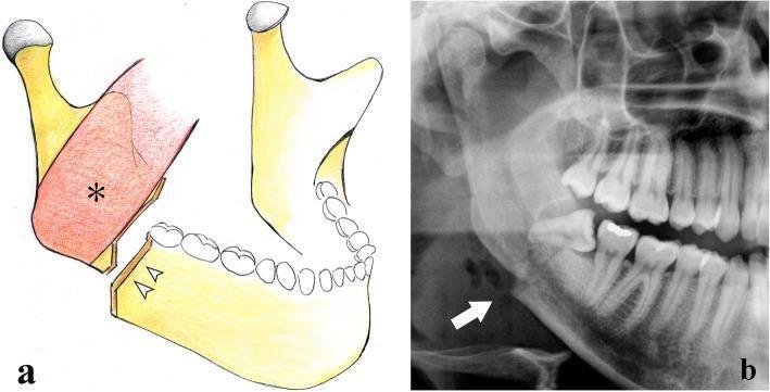
This composite educational image illustrates a mandibular angle fracture through an anatomical diagram (a) and a cropped panoramic radiograph (b). Panel (a) shows an anatomical illustration of a vertical, unfavorable fracture located distal to the third molar. The diagram demonstrates significant displacement of the distal bone fragment (ramus and condyle), which is pulled superiorly and medially by the masseter muscle (indicated by an asterisk). Panel (b) provides clinical correlation via an X-ray (orthopantomogram) showing a radiolucent fracture line through the mandibular angle. An impacted third molar is visible at the site of the fracture (indicated by an arrow), representing a common predisposing factor for fractures in this region due to localized bone weakening. The content focuses on the pathophysiology and radiographic presentation of maxillofacial trauma, specifically highlighting how muscular forces contribute to fragment displacement in mandibular angle injuries.
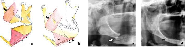
Educational composite image illustrating mandibular horizontal branch fractures, categorized by their biomechanical stability. Panels A and B are anatomical diagrams showing the interplay between fracture orientation and muscular forces. In panel A, an 'unfavorable' fracture is shown with a downward and posterior line; the masseter (black arrow) pulls the distal fragment superiorly, while the mylohyoid (asterisk), geniohyoid (white arrow), and digastric (black arrowhead) muscles pull the mesial fragment inferiorly, causing significant displacement. Panel B illustrates a 'favorable' fracture with a downward and anterior direction, where muscular forces impact the fragments together, maintaining alignment. Panels C and D provide clinical correlation via cropped panoramic radiographs of edentulous patients. Radiograph C demonstrates an unfavorable fracture with a clear step-off and misalignment (arrow). Radiograph D shows a favorable fracture where the fragments remain in contact without significant displacement (arrowhead). This content serves to teach the radiographic classification and biomechanical principles of mandibular trauma and maxillofacial surgery.
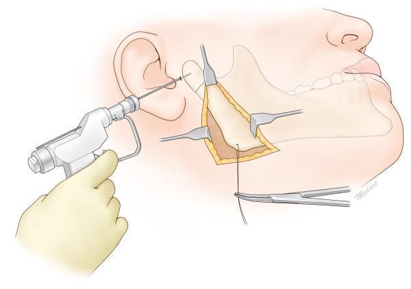
This medical anatomical diagram illustrates the surgical reduction of a mandibular condylar neck fracture using the Risdon approach. The illustration depicts a lateral view of the human face with a surgical incision below the mandibular angle, exposing the posterior ramus and subcondylar region. Three retractors are positioned to maintain the surgical field, providing direct visualization of the fracture site and the masseter muscle detachment. A threaded Kirschner wire (K-wire) is being inserted percutaneously through a preauricular stab incision into the proximal fractured condylar segment using a handheld power drill. Simultaneously, a wire traction technique is demonstrated at the inferior border of the mandibular angle, secured by a hemostat, to pull the distal segment inferiorly for anatomic alignment. This procedure is commonly used in oral and maxillofacial surgery for pediatric or complex condylar fractures to facilitate reduction under direct vision while minimizing risks to the facial nerve branches, specifically the marginal mandibular nerve.
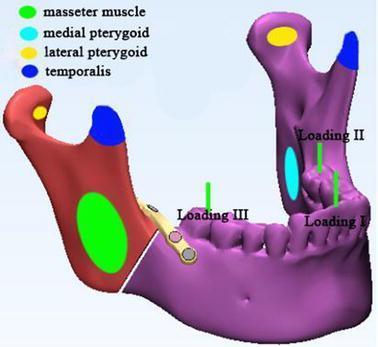
This anatomical diagram and biomechanical model illustrates the forces acting on a human mandible with a right-sided angle fracture fixed with a mini-plate. The 3D model identifies muscle attachment zones and occlusal loading points for finite element analysis. Muscle force applications are represented by colored ovals: green for the masseter muscle on the lateral ramus, cyan for the medial pterygoid on the medial ramus, yellow for the lateral pterygoid at the condylar process, and blue for the temporalis muscle at the coronoid process. Three occlusal loading situations are marked with vertical green lines: Loading I at the incisor (125 N), Loading II at the left second molar (250 N), and Loading III at the right second molar (250 N). The image demonstrates the clinical relevance of masticatory force distribution on fracture stability and internal fixation hardware, specifically in the context of mandibular angle fracture management.
Horizontally Unfavorable Mandibular Angle Fracture
Definition and Classification
- Vertically - in the coronal (frontal) plane
- Horizontally - in the sagittal (side) plane
Anatomical Basis and Muscle Forces
| Muscle | Attachment | Action on fragments |
|---|---|---|
| Masseter | Lateral ramus/angle | Pulls posterior fragment superiorly |
| Medial pterygoid | Medial ramus/angle | Pulls posterior fragment superiorly and medially |
| Mylohyoid, geniohyoid, digastric | Anterior body | Pull anterior fragment inferiorly and posteriorly |
Comparison: Favorable vs Unfavorable (Horizontal Plane)
| Feature | Horizontally Favorable | Horizontally Unfavorable |
|---|---|---|
| Fracture line direction (sagittal view) | Downward and forward (anteroinferiorly) | Downward and backward (posteroinferiorly) |
| Effect of muscle pull | Fragments are compressed together | Fragments are distracted apart |
| Displacement | Minimal | Significant |
| Stability | Relatively stable | Unstable - requires fixation |
Clinical Significance
- Displacement and malocclusion - The distracting muscle forces cause significant step deformity and occlusal disturbance.
- Requires open reduction and internal fixation (ORIF) - Because the fracture is inherently unstable, IMF (intermaxillary fixation) alone is insufficient. A miniplate at the superior border (tension band, per the Champy technique) is the standard approach for angle fractures.
- Role of third molars - An unerupted or impacted mandibular third molar in the line of fracture weakens the angle (thins the bone) and predisposes to angle fractures at this site. The tooth in the fracture line usually needs extraction.
- Imaging - Panoramic radiograph (OPG/Panorex) is the first-line imaging study and clearly demonstrates misalignment due to distracting forces. CT with coronal sections is indicated for complex or comminuted fractures.
- Risk of complication - If not rigidly fixed, these fractures carry higher risk of malunion, non-union, and post-traumatic malocclusion.
- Tintinalli's Emergency Medicine, Mandible Fractures section
- Scott-Brown's Otorhinolaryngology Head & Neck Surgery, Vol 1, p. 1240