
Wrist tendon
wrist tendons anatomy diagram flexor extensor
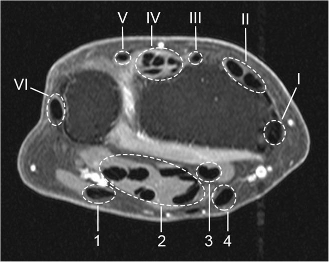
This diagnostic image is an axial T1-weighted, post-gadolinium, fat-saturated MRI of the human wrist, specifically used for evaluating tenosynovitis. The image demonstrates the cross-sectional anatomy of the flexor and extensor tendon regions, which are outlined with dashed white circles and labeled for educational indexing. The six extensor compartments are indicated by Roman numerals (I-VI): I (abductor pollicis longus and extensor pollicis brevis), II (extensor carpi radialis longus/brevis), III (extensor pollicis longus), IV (extensor digitorum communis and indicis proprius), V (extensor digiti quinti), and VI (extensor carpi ulnaris). The four flexor regions are marked with Arabic numerals (1-4): 1 (flexor carpi ulnaris), 2 (ulnar bursa containing flexor digitorum tendons), 3 (flexor pollicis longus in the radial bursa), and 4 (flexor carpi radialis). The modality highlights synovial enhancement, where high signal intensity in these regions indicates inflammation (tenosynovitis). This visual is a primary reference for musculoskeletal radiology and rheumatology, illustrating standard anatomical landmarks for clinical scoring of inflammatory wrist conditions.
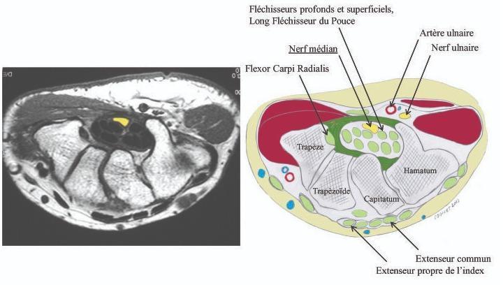
This medical visual consists of a side-by-side comparison between an axial magnetic resonance imaging (MRI) scan of the human wrist and a corresponding anatomical cross-section diagram. The image illustrates the anatomy of the carpal tunnel and surrounding structures. Key elements identified include the carpal bones (trapezium, trapezoid, capitate, and hamate) forming the floor and walls of the tunnel. Centrally located within the carpal tunnel, the median nerve is highlighted in yellow, positioned superficially to the deep and superficial flexor tendons and the long flexor tendon of the thumb. The flexor carpi radialis is shown in its distinct compartment. Outside the flexor retinaculum on the ulnar side, the ulnar artery and ulnar nerve are clearly demarcated. Posteriorly, the extensor tendons, including the extensor digitorum and extensor indicis, are visible. This educational material is designed to demonstrate the spatial relationship of the median nerve within the confined carpal space, which is clinically relevant for diagnosing and treating carpal tunnel syndrome.
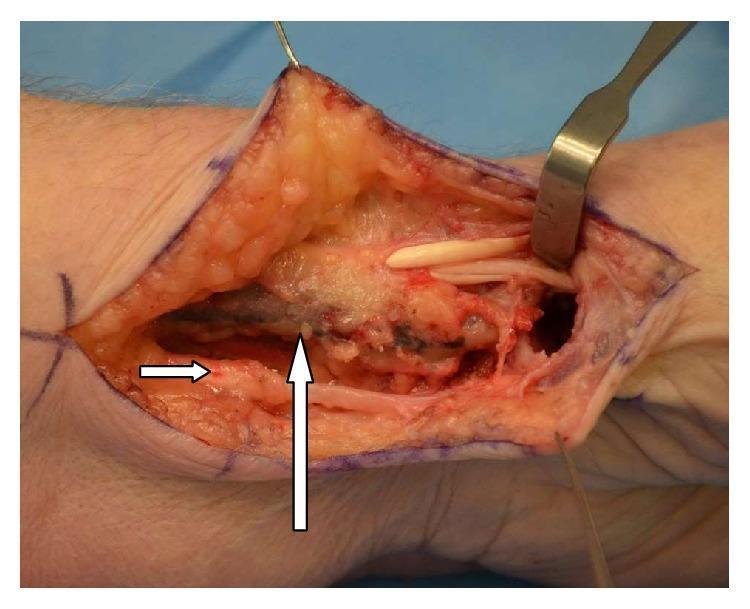
This clinical photograph displays a surgical dissection of the volar and radial aspects of a human left wrist during a trapeziectomy and ligament reconstruction procedure. The surgical site reveals the underlying anatomy with several key structures annotated. A vertical arrow points to the radial artery, which appears as a distinct, dark vascular cord. Notably, the flexor carpi radialis (FCR) tendon is congenitally absent in the expected location ulnar to the radial artery, showing only soft tissue and fat instead of a discrete tendon. A horizontal arrow indicates the palmaris longus tendon, visible as a superficial, striated, cord-like structure located inferiorly. Superiorly, the abductor pollicis longus (APL) and extensor pollicis brevis (EPB) tendons are identified near the thumb base, retracted to expose the deeper surgical field. This image serves as an educational example of anatomical variation in hand surgery, specifically the rare absence of the FCR tendon and its impact on surgical planning for carpometacarpal (CMC) joint osteoarthritis.
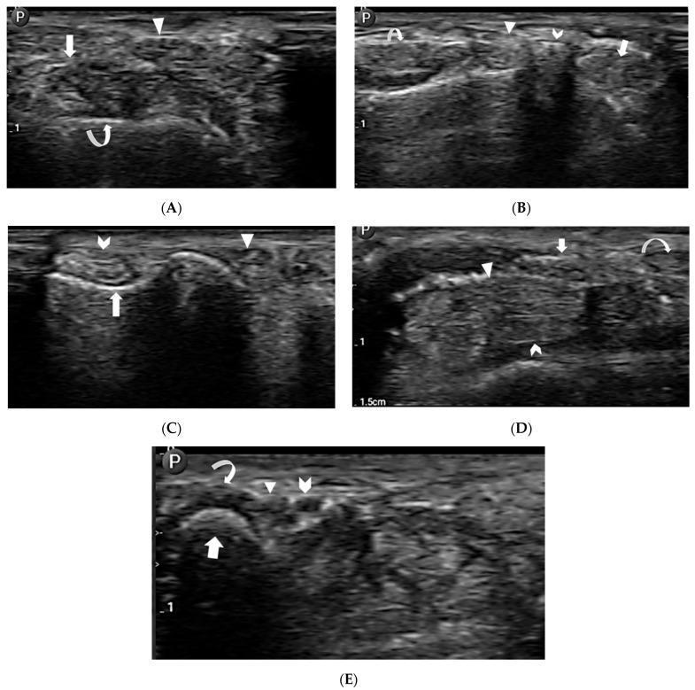
A series of five musculoskeletal ultrasound (MSKUS) images (A-E) demonstrating the transverse cross-sectional anatomy of the wrist's extensor compartments, carpal tunnel, and Guyon's canal. (A) Shows the radial aspect with the first extensor compartment (arrow), third extensor compartment (arrowhead), and the hyperechoic cortex of the radial styloid process (curved arrow). (B) Visualizes the second (arrow), third (arrowhead), and fourth (curved arrow) extensor compartments adjacent to Lister’s tubercle (chevron). (C) Displays the ulnar side including the fifth (arrowhead) and sixth (chevron) extensor compartments, with the distal ulnar groove (arrow). (D) Focuses on the carpal tunnel, identifying the median nerve (arrow), flexor digitorum superficialis (arrowhead), flexor digitorum profundus (chevron), and flexor carpi radialis (curved arrow). (E) Illustrates Guyon's canal containing the ulnar artery (chevron), ulnar nerve (arrowhead), and flexor carpi ulnaris tendon (curved arrow) superior to the triquetrum bone (arrow). The images utilize annotations to highlight variations in echogenicity and spatial relationships between tendons, nerves, and bony landmarks for diagnostic and interventional mapping.
Wrist Tendons
Flexor Tendons
| Tendon | Action |
|---|---|
| Flexor carpi radialis (FCR) | Wrist flexion + radial deviation |
| Flexor carpi ulnaris (FCU) | Wrist flexion + ulnar deviation |
| Palmaris longus | Wrist flexion (absent in ~15% of people; has no synovial sheath) |
| Tendon | Insertion | Action |
|---|---|---|
| Flexor digitorum superficialis (FDS) x4 | Volar base of middle phalanx (digits 2-5) | Flexes PIP and MCP joints |
| Flexor digitorum profundus (FDP) x4 | Volar base of distal phalanx (digits 2-5) | Flexes DIP joint primarily; also PIP + MCP |
| Flexor pollicis longus (FPL) x1 | Base of distal phalanx of thumb | Flexes thumb IP joint |
The ulnar artery, ulnar nerve, and palmaris longus tendon all travel anterior to the flexor retinaculum through Guyon's canal - they do NOT pass through the carpal tunnel.
- Gray's Anatomy for Students, p. 919
Extensor Tendons
| Compartment | Tendons | Key action |
|---|---|---|
| I | Abductor pollicis longus (APL) + Extensor pollicis brevis (EPB) | Thumb abduction/extension |
| II | Extensor carpi radialis longus (ECRL) + brevis (ECRB) | Wrist extension + radial deviation |
| III | Extensor pollicis longus (EPL) | Thumb IP extension |
| IV | Extensor digitorum communis (EDC) + Extensor indicis proprius (EIP) | Finger extension |
| V | Extensor digiti minimi (EDM / EDQ) | Little finger extension |
| VI | Extensor carpi ulnaris (ECU) | Wrist extension + ulnar deviation |
- Tintinalli's Emergency Medicine, p. 1826
- Grainger & Allison's Diagnostic Radiology, p. 986
Key Clinical Points
| Condition | Tendon(s) Involved |
|---|---|
| De Quervain's tenosynovitis | Compartment I (APL + EPB) - stenosing tenosynovitis at radial styloid |
| Carpal tunnel syndrome (CTS) | Compression of median nerve in carpal tunnel; can be caused by flexor tenosynovitis (e.g., rheumatoid arthritis) |
| ECU tenosynovitis | Compartment VI - common in RA and ulnar styloid erosions |
| Mallet finger | Disruption of terminal extensor tendon at DIP |
| Boutonniere deformity | Central slip (EDC) injury at PIP; lateral bands migrate volarly |
| Jersey finger | FDP avulsion from distal phalanx |
Imaging at the Wrist
"All Anatomists Excel, Digesting Everything Exceedingly" APL/EPB - ECRL/ECRB - EPL - EDC/EIP - EDM - ECU
C1 to c12
What are you asking about when you say C1 to C12?
cranial nerves CN I to XII diagram overview anatomy
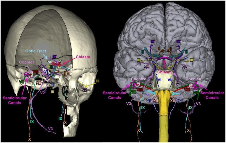
A 3D anatomical reconstruction showcasing the segmentation and spatial orientation of the 12 pairs of human cranial nerves (CN I–XII). The image presents two views: a lateral perspective within a partially transparent skull (left) and an anterior-inferior view relative to the brain and brainstem (right). Each nerve is color-coded for identification: CN I (Olfactory), CN II (Optic) with the optic chiasm and tract, CN III (Oculomotor), CN IV (Trochlear), CN V (Trigeminal) including V2 (maxillary) and V3 (mandibular) divisions, CN VI (Abducens), CN VII (Facial), CN VIII (Vestibulocochlear), CN IX (Glossopharyngeal), CN X (Vagus), CN XI (Accessory), and CN XII (Hypoglossal). Key inner ear structures, including the snail-shaped cochlea and the loop-like semicircular canals, are visualized in relation to the facial and vestibulocochlear nerves. This diagnostic-quality illustration demonstrates the complex neuroanatomical pathways through the skull base and their origins at the brainstem, serving as a pedagogical tool for neurology, radiology, and neurosurgery training.
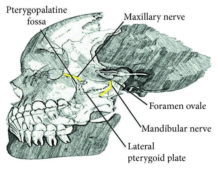
Anatomical diagram of a lateral view of the human skull, specifically focusing on the deep facial nerves and related osteological landmarks. The illustration highlights the trigeminal nerve (CN V) divisions using yellow color-coding. The maxillary nerve (V2) is shown exiting the cranial cavity through the foramen rotundum to enter the pterygopalatine fossa, located anterior to the lateral pterygoid plate. The mandibular nerve (V3) is depicted exiting via the foramen ovale, descending posterior to the lateral pterygoid plate. Key labels include the Pterygopalatine fossa, Maxillary nerve, Foramen ovale, Mandibular nerve, and Lateral pterygoid plate. The diagram serves as an educational resource for understanding the regional anatomy required for performing nerve blocks and identifying neural pathways within the infratemporal and pterygopalatine regions.
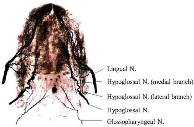
This diagnostic image demonstrates the whole-mount neural anatomy of a human adult tongue using Sihler’s staining technique. This specialized clear-and-stain method renders muscle tissue translucent while staining nerve fibers dark, allowing for precise visualization of the three-dimensional intramuscular nerve distribution. The image displays the relative positions and branching patterns of key cranial nerves. The Lingual Nerve (branch of CN V3) is visible providing sensory innervation to the anterior two-thirds. The Hypoglossal Nerve (CN XII) is shown with its medial and lateral branches situated between the more lateral Lingual Nerve and the more medial/inferior Glossopharyngeal Nerve (CN IX) in the posterior tongue. The anatomical mapping highlights the complex plexus formation and terminal branching critical for coordinating sensorimotor functions such as deglutition and speech. This visual serves as a primary reference for understanding the dense innervation patterns required for motor control by CN XII and sensory perception by CN IX and CN V.
Cranial Nerves CN I to CN XII
Quick Reference Table
| # | Name | Type | Skull Exit | Key Function |
|---|---|---|---|---|
| I | Olfactory | Sensory | Cribriform plate (ethmoid) | Smell |
| II | Optic | Sensory | Optic canal | Vision |
| III | Oculomotor | Motor + Parasympathetic | Superior orbital fissure | Moves eye (SR, MR, IR, IO); elevates eyelid; pupil constriction (miosis) + lens accommodation |
| IV | Trochlear | Motor | Superior orbital fissure | Superior oblique muscle (eye depression + intorsion) |
| V | Trigeminal | Sensory + Motor | V1: superior orbital fissure; V2: foramen rotundum; V3: foramen ovale | Face sensation (all 3 divisions); mastication muscles (V3 only) |
| VI | Abducens | Motor | Superior orbital fissure | Lateral rectus (eye abduction) |
| VII | Facial | Sensory + Motor + Parasympathetic | Internal acoustic meatus → stylomastoid foramen | Facial expression; taste anterior 2/3 tongue; lacrimal/submandibular/sublingual glands |
| VIII | Vestibulocochlear | Sensory | Internal acoustic meatus | Hearing (cochlear division); Balance (vestibular division) |
| IX | Glossopharyngeal | Sensory + Motor + Parasympathetic | Jugular foramen | Taste + sensation posterior 1/3 tongue; carotid body/sinus; parotid gland; stylopharyngeus |
| X | Vagus | Sensory + Motor + Parasympathetic | Jugular foramen | Larynx, pharynx, thoracic + abdominal viscera (foregut/midgut); major parasympathetic outflow |
| XI | Accessory | Motor | Jugular foramen | Sternocleidomastoid + trapezius muscles |
| XII | Hypoglossal | Motor | Hypoglossal canal | All tongue muscles (intrinsic + extrinsic: hyoglossus, genioglossus, styloglossus) |
- Gray's Anatomy for Students, pp. 987, 1034-1035
Fiber Type Components
| Abbreviation | Full Name | Function | Nerves |
|---|---|---|---|
| GSA | General somatic afferent | Touch, pain, temperature | V, VII, IX, X |
| GVA | General visceral afferent | Visceral sensation | IX, X |
| SA | Special afferent | Smell, taste, vision, hearing, balance | I, II, VII, VIII, IX, X |
| GSE | General somatic efferent | Voluntary skeletal muscle | III, IV, VI, XII |
| GVE | General visceral efferent | Smooth muscle, glands (parasympathetic) | III, VII, IX, X |
| BE | Branchial efferent | Pharyngeal arch-derived muscles | V, VII, IX, X, XI |
Each Nerve in Detail
- Pure sensory; arises from olfactory receptor neurons in the nasal mucosa
- Passes through the cribriform plate of the ethmoid
- Damage: anosmia (loss of smell); often injured in head trauma
- Pure sensory; technically an extension of the CNS (not a true peripheral nerve - surrounded by meninges)
- Passes through the optic canal; fibers decussate at the optic chiasm
- Damage: visual field defects depending on lesion location
- Motor to 4 extraocular muscles: superior rectus, medial rectus, inferior rectus, inferior oblique; plus levator palpebrae superioris
- Parasympathetic (GVE): ciliary ganglion → sphincter pupillae (miosis) + ciliary muscle (accommodation)
- Damage: "down and out" eye, ptosis, dilated fixed pupil (blown pupil)
- Smallest cranial nerve; only one that exits the dorsal brainstem
- Motor to superior oblique (depression + intorsion of adducted eye)
- Damage: vertical diplopia, head tilt to compensate
- Three divisions:
- V1 (Ophthalmic) - forehead, scalp, upper eyelid, nose tip, cornea (corneal reflex afferent)
- V2 (Maxillary) - cheek, upper lip, upper teeth, palate
- V3 (Mandibular) - lower lip, lower teeth, chin, anterior 2/3 tongue (general sensation only); motor to masseter, temporalis, pterygoids, mylohyoid, anterior digastric, tensor tympani, tensor veli palatini
- Ganglion: trigeminal (Gasserian) ganglion
- Motor to lateral rectus only
- Long intracranial course; most vulnerable to raised intracranial pressure
- Damage: medial deviation of eye, horizontal diplopia on lateral gaze
- Motor (BE): muscles of facial expression, scalp, stapedius, posterior digastric, stylohyoid
- Sensory (SA): taste from anterior 2/3 tongue via chorda tympani
- Parasympathetic (GVE): lacrimal gland (via greater petrosal nerve); submandibular + sublingual glands (via chorda tympani)
- Ganglion: geniculate ganglion
- Damage: Bell's palsy (LMN lesion - entire ipsilateral face droops); UMN lesion spares forehead
- Pure sensory; two divisions:
- Cochlear - hearing (organ of Corti)
- Vestibular - balance (semicircular canals, utricle, saccule)
- Passes through internal acoustic meatus alongside CN VII
- Damage: sensorineural hearing loss, tinnitus, vertigo, nystagmus
- Sensory: posterior 1/3 tongue (taste + general sensation), oropharynx, middle ear, carotid body (chemoreceptor) + carotid sinus (baroreceptor)
- Motor (BE): stylopharyngeus
- Parasympathetic: parotid gland (via lesser petrosal nerve → otic ganglion)
- Damage: loss of gag reflex (afferent limb), loss of taste posterior tongue
- Exits jugular foramen; descends through neck into thorax and abdomen
- Motor: pharynx, larynx (recurrent laryngeal + superior laryngeal branches), one tongue muscle (palatoglossus), soft palate
- Parasympathetic: heart (slows HR), lungs, entire GI tract to splenic flexure
- Sensory: larynx, laryngopharynx, aortic arch baroreceptors/chemoreceptors, thoracic + abdominal viscera
- Damage: hoarseness (recurrent laryngeal nerve), dysphagia, deviation of uvula away from lesion
- Two roots: cranial (joins vagus) + spinal (C1-C5, enters skull through foramen magnum)
- Motor to sternocleidomastoid (head turning) + trapezius (shoulder elevation)
- Exits via jugular foramen
- Damage: weakness turning head to opposite side; drooping shoulder, winging of scapula
- Pure motor to all tongue muscles (intrinsic muscles + hyoglossus, genioglossus, styloglossus)
- Exits via hypoglossal canal
- Damage: tongue deviates toward the side of the lesion on protrusion (LMN)
Parasympathetic Cranial Nerves (the "SLUDD" nerves)
| Nerve | Ganglion | Target |
|---|---|---|
| CN III | Ciliary ganglion | Pupil constriction, lens accommodation |
| CN VII | Pterygopalatine + submandibular ganglia | Lacrimal, submandibular, sublingual glands; nasal mucosa |
| CN IX | Otic ganglion | Parotid gland |
| CN X | Terminal ganglia in organ walls | Heart, lungs, GI tract to splenic flexure |
Memory Aids
"Oh Oh Oh To Touch And Feel Very Good Velvet. Ah Heaven!" Olfactory, Optic, Oculomotor, Trochlear, Trigeminal, Abducens, Facial, Vestibulocochlear, Glossopharyngeal, Vagus, Accessory, Hypoglossal
"Some Say Marry Money But My Brother Says Big Brains Matter Most" S, S, M, M, B, M, B, S, B, B, M, M
- Cribriform plate → I
- Optic canal → II
- Superior orbital fissure → III, IV, V1, VI
- Foramen rotundum → V2
- Foramen ovale → V3
- Internal acoustic meatus → VII, VIII
- Jugular foramen → IX, X, XI
- Hypoglossal canal → XII
Vertebrae
vertebral column spine all regions cervical thoracic lumbar sacral anatomy diagram
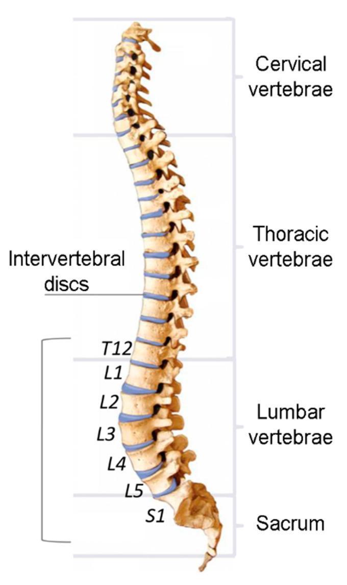
An anatomical diagram of the human spinal column shown in a lateral (sagittal) view, highlighting the primary vertebral regions and intervertebral components. The column illustrates natural physiological curvatures, including cervical lordosis, thoracic kyphosis, and lumbar lordosis. The vertebrae are categorized into four distinct sections: Cervical vertebrae (superior), Thoracic vertebrae, Lumbar vertebrae, and the Sacrum (inferior). Blue-tinted bands represent the intervertebral discs situated between adjacent vertebral bodies, acting as fibrocartilaginous shock absorbers. Specific focus is directed toward the lower spine, with labels identifying the disc levels from T12 (twelfth thoracic vertebra) through the five lumbar vertebrae (L1-L5) to S1 (first sacral segment). This illustration is designed for educational use in understanding spinal anatomy, biomechanics, and clinical localization of disc levels for diagnostic or therapeutic assessments.
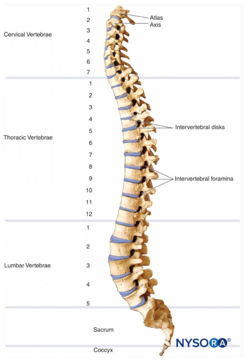
Anatomical diagram of the human vertebral column shown from a lateral perspective. The illustration categorizes the spine into five primary regions: cervical vertebrae (C1-C7), thoracic vertebrae (T1-T12), lumbar vertebrae (L1-L5), sacrum, and coccyx. Specific anatomical structures are highlighted, including the Atlas (C1) and Axis (C2). Intervertebral discs are represented as blue segments situated between the vertebral bodies, demonstrating their role as shock absorbers and structural spacers. The intervertebral foramina, which serve as exit points for spinal nerves, are clearly visible as openings between adjacent pedicles, particularly in the thoracic and lumbar segments. The diagram illustrates the natural physiological curvatures of the spine, including cervical lordosis, thoracic kyphosis, and lumbar lordosis. This visual resource is intended for medical education regarding spinal anatomy, level identification for clinical diagnosis of spinal cord injuries, and understanding the skeletal framework of the axial skeleton.
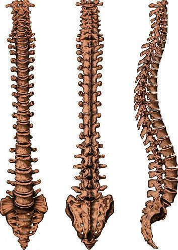
This anatomical diagram presents a comprehensive three-view study of the human vertebral column, including anterior (frontal), posterior (rear), and lateral (side) perspectives. The illustration highlights the structural organization of the spine, starting from the cervical vertebrae down through the thoracic and lumbar regions, terminating at the fused sacrum and the coccyx. Each vertebra is depicted with distinct anatomical features: the anterior view emphasizes the vertebral bodies and intervertebral disc spaces; the posterior view showcases the spinous and transverse processes; and the lateral view clearly demonstrates the four physiological curvatures—cervical lordosis, thoracic kyphosis, lumbar lordosis, and sacral kyphosis. This 'S' shaped alignment is shown as essential for weight-bearing, flexibility, and protecting the spinal cord. The diagram serves as an educational resource for studying osteology, spinal biomechanics, and regional anatomy, illustrating the progressive increase in vertebral size to accommodate increasing gravitational loads.
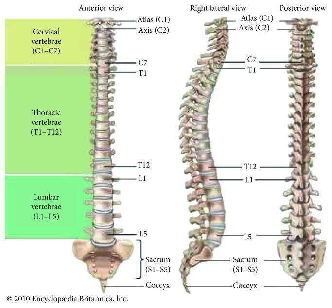
This anatomical diagram presents three perspectives of the human vertebral column: anterior view, right lateral view, and posterior view. The illustration categorizes the 33 vertebrae into five distinct regions, color-coded for clarity: cervical (C1–C7), thoracic (T1–T12), lumbar (L1–L5), the fused sacrum (S1–S5), and the coccyx. Key anatomical landmarks are labeled, including the Atlas (C1) and Axis (C2). The anterior and posterior views demonstrate the vertical alignment and central symmetry of the spine. The right lateral view illustrates the physiological curvatures of the column, showing the cervical lordosis (inward curve), thoracic kyphosis (outward curve), lumbar lordosis (inward curve), and the sacrococcygeal curve. This comparison highlights the structural organization of individual vertebrae, the intervertebral discs, and the overall S-shaped profile necessary for balance and shock absorption. The diagram serves as a foundational educational tool for understanding spinal anatomy, regional segmentation, and normal postural curvature in clinical and musculoskeletal medicine.
typical vertebra anatomy parts body pedicle lamina spinous transverse process
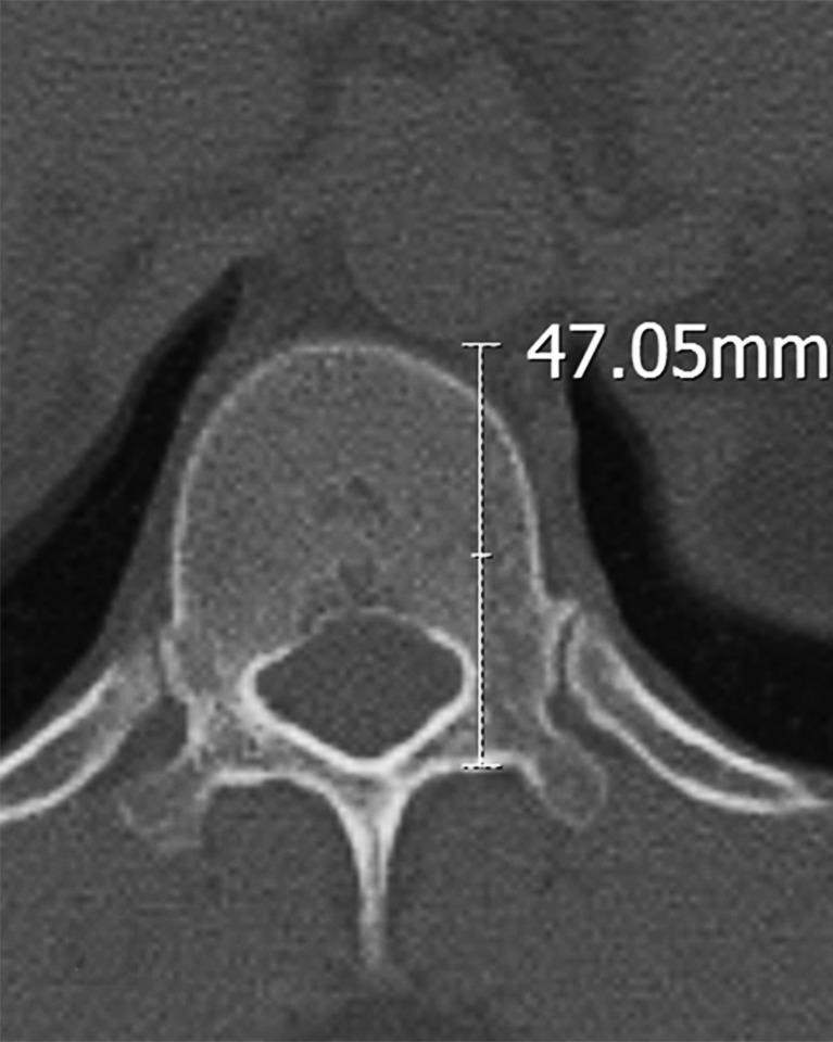
This diagnostic axial CT scan image shows a transverse section of a human vertebra, specifically identified as the T12 level. The bony anatomy includes the rounded vertebral body, the central spinal canal, bilateral pedicles, and a posterior spinous process. A digital linear measurement is overlaid on the image, showing a value of 47.05mm. This caliper measurement calculates the distance between the anterior margin of the vertebral body and the posterior wall of the spinal canal (lamina). The image demonstrates clinical morphometric analysis used in preoperative planning for spinal surgery, such as assessing pedicle screw trajectory and length relative to surrounding neurovascular structures like the thoracic aorta. The scan provides high-contrast detail of the cortical and cancellous bone density, typical of bone-window CT imaging for musculoskeletal assessment.
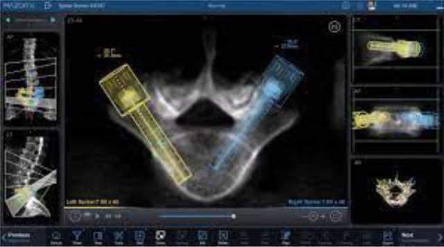
This diagnostic image displays the software interface for the Mazor X robotic guidance system used in preoperative spinal surgical planning. The central panel features a transverse (axial) CT scan reconstruction of a lumbar vertebra, showing the vertebral body, pedicles, lamina, and spinous process. Overlaid on the anatomy are color-coded graphical representations of pedicle screws: a yellow screw on the left and a blue screw on the right. These 3D models demonstrate the planned trajectory, diameter, and insertion depth through the pedicles into the vertebral body. Additional peripheral panels provide multiplanar views, including a sagittal reconstruction of the spine on the left and specialized coronal and side-view alignments on the right. The interface facilitates optimization of construct definition, allowing surgeons to select appropriate screw dimensions based on individual patient anatomy. This visual illustrates the integration of advanced medical imaging with robotic navigation for spinal instrumentation.
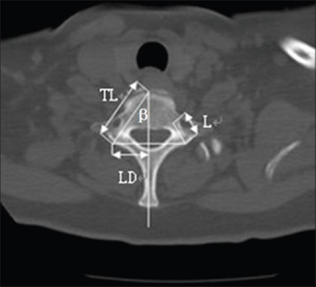
**Modality:** Computed Tomography (CT), Axial plane. **Anatomy:** Cervical spine, specifically the C7 vertebra. Key landmarks include the vertebral body, spinal canal, pedicles, transverse processes, and spinous process. **Description:** This image demonstrates a quantitative morphometric analysis of the C7 vertebra. Linear and angular measurements are overlaid on the osseous structures to evaluate pedicle morphology. - **TL (Total Length):** Chord length measurement from the posterior entry point of the pedicle to the anterior cortex of the vertebral body. - **L (Pedicle Width):** Transverse diameter of the pedicle. - **LD (Lamina Distance):** Horizontal distance from the midline to the lateral aspect of the vertebral arch. - **β (Pedicle Angle):** The transverse angulation of the pedicle axis relative to the mid-sagittal plane. **Clinical Context:** These measurements are typically utilized for preoperative planning in spinal surgery, specifically for the safe placement of transpedicular screws. The image highlights the anatomical constraints and the trajectory required to avoid neurovascular injury to the spinal cord or vertebral arteries. No acute fracture or gross pathology is visualized in the displayed bone window.
The Vertebrae - Complete Overview
Vertebral Column at a Glance
| Region | Count | Moveable? | Curve |
|---|---|---|---|
| Cervical | 7 (C1-C7) | Yes | Lordosis (anterior convexity) |
| Thoracic | 12 (T1-T12) | Yes | Kyphosis (posterior convexity) |
| Lumbar | 5 (L1-L5) | Yes | Lordosis (anterior convexity) |
| Sacral | 5 (S1-S5) fused | No (fused in adults) | Kyphosis (sacral curve) |
| Coccygeal | 4 (Co1-Co4) fused | No | - |
| Total | 33 |
Parts of a Typical Vertebra
| Part | Description |
|---|---|
| Vertebral body | Anterior weight-bearing part; increases in size from top to bottom |
| Pedicles (x2) | Short bony pillars connecting body to arch |
| Laminae (x2) | Flat sheets of bone from pedicles meeting in midline; form roof of arch |
| Vertebral arch | Pedicles + laminae together; encircles the vertebral foramen |
| Vertebral foramen | Space through which the spinal cord passes |
| Spinous process | Projects posteriorly from junction of laminae; muscle/ligament attachment |
| Transverse processes (x2) | Project posterolaterally from pedicle-lamina junction; muscle/ligament attachment |
| Superior articular processes (x2) | Articulate with inferior articular processes of vertebra above |
| Inferior articular processes (x2) | Articulate with superior articular processes of vertebra below |
| Intervertebral notches | Notches on pedicles form intervertebral foramina through which spinal nerves exit |
- Gray's Anatomy for Students, p. 84
Regional Features
1. Cervical Vertebrae (C1-C7)
| Feature | Description |
|---|---|
| Size | Smallest vertebrae |
| Body | Short, square; concave superior surface, convex inferior surface |
| Spinous process | Short and bifid (forked) - C2 to C6 |
| Transverse process | Trough-shaped with foramen transversarium |
| Vertebral foramen | Triangular and large |
- Ring-shaped; no vertebral body (body fused to C2 to become the dens during development)
- No intervertebral disc between C1 and C2
- Composed of anterior arch, posterior arch, and two lateral masses
- Each lateral mass articulates above with occipital condyle (atlanto-occipital joint - nodding "yes")
- Large transverse processes as muscle levers
- Has a tooth-like dens (odontoid process) projecting superiorly from the body
- The dens acts as a pivot for rotation of the atlas and head (atlanto-axial joint - shaking "no")
- Dens held in place by the transverse ligament of the atlas
- Alar ligaments connect dens to occipital condyles; check excessive rotation
- Long, non-bifid spinous process - easily palpable at the base of the neck
- Landmark for counting vertebral levels
2. Thoracic Vertebrae (T1-T12)
| Feature | Description |
|---|---|
| Size | Medium |
| Body | Heart-shaped from above; has superior and inferior costal facets for rib head articulation |
| Spinous process | Long, slender, pointing sharply downward (overlapping the vertebra below) |
| Transverse process | Has transverse costal facets for articulation with rib tubercle |
| Vertebral foramen | Circular and small |
- T1: full superior facet for 1st rib + small inferior facet for 2nd rib
- T10-T12: only one costal facet each (for their own rib only)
- T11, T12: no transverse costal facets (ribs 11, 12 are "floating" ribs)
3. Lumbar Vertebrae (L1-L5)
| Feature | Description |
|---|---|
| Size | Largest vertebrae |
| Body | Cylindrical, massive |
| Spinous process | Short, stubby, projects horizontally posteriorly |
| Transverse processes | Generally thin and long; L5 has massive cone-shaped processes for iliolumbar ligaments |
| Vertebral foramen | Triangular, larger than thoracic |
| Articular facets | Face medially/laterally (restrict rotation, permit flexion/extension) |
4. Sacrum (S1-S5 fused)
- Concave anterior (pelvic) surface with 4 pairs of anterior sacral foramina (for anterior rami of S1-S4)
- Convex posterior surface with 4 pairs of posterior sacral foramina (for posterior rami of S1-S4)
- Articulates superiorly with L5 (lumbosacral joint) and laterally with pelvic bones at sacroiliac joints (large L-shaped auricular surfaces)
- The sacral canal is the continuation of the vertebral canal; terminates as the sacral hiatus (used for caudal epidural injections)
- Sacral promontory: anterior projecting rim of S1 body - important obstetric landmark
5. Coccyx (Co1-Co4 fused)
- 3-5 fused rudimentary vertebrae (usually 4)
- Remnant of the tail; provides attachment for pelvic floor muscles and ligaments
- Articulates with the apex of the sacrum
Spinal Curves and Clinical Significance
| Curve | Region | Type | Clinical Note |
|---|---|---|---|
| Cervical lordosis | C1-C7 | Secondary | Exaggerated = cervical lordosis (text neck) |
| Thoracic kyphosis | T1-T12 | Primary | Exaggerated = kyphosis (hunchback) |
| Lumbar lordosis | L1-L5 | Secondary | Exaggerated = hyperlordosis; flattened in disc prolapse |
| Sacral kyphosis | S1-S5 | Primary | Fixed in adults |
Key Clinical Points
| Condition | Level/Structure |
|---|---|
| Lumbar puncture | L3/L4 or L4/L5 (below conus medullaris at L1-L2) |
| Caudal epidural | Sacral hiatus |
| Jefferson fracture | C1 atlas (burst fracture from axial load) |
| Hangman's fracture | C2 pedicles (hyperextension) |
| Odontoid fracture | C2 dens |
| Chance fracture | Lumbar vertebra (seatbelt flexion-distraction) |
| Disc prolapse | Most common at L4/L5 and L5/S1 |
| Vertebra prominens | C7 - surface landmark for level counting |
- Gray's Anatomy for Students, pp. 84-87
- Forensic Anthropology: A Comprehensive Introduction, p. 115