
Describe the volar plate used for distal end radius fracture
volar locking plate distal radius fracture fixation
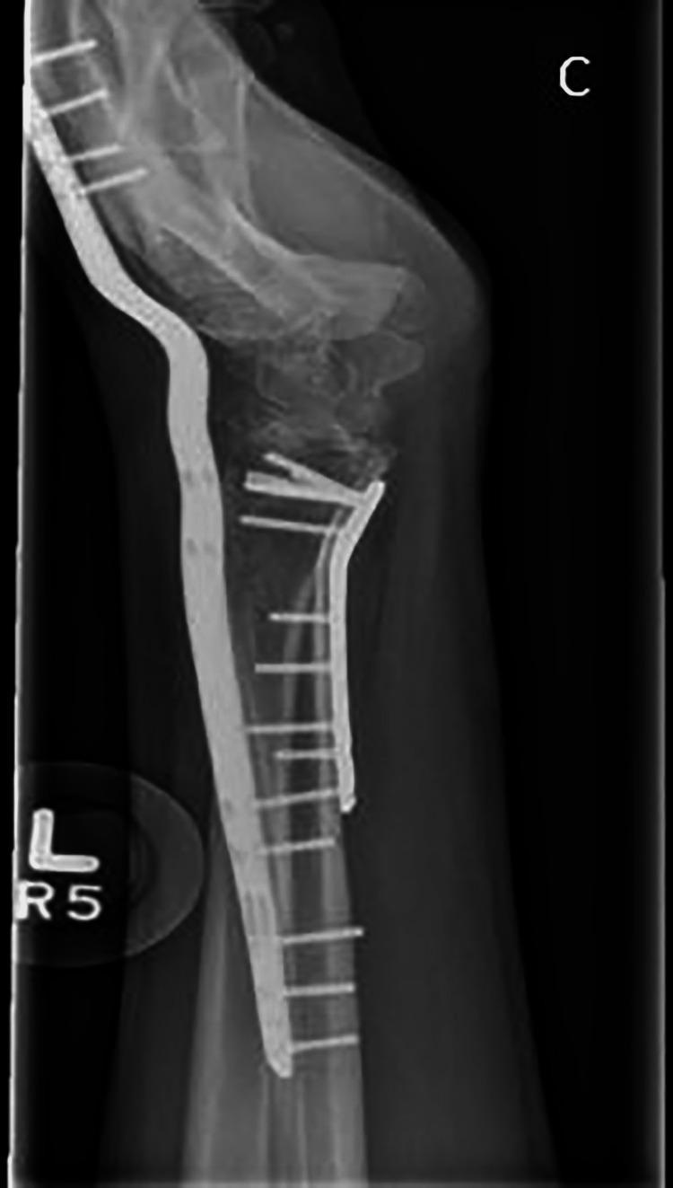
This lateral X-ray radiograph of the left wrist demonstrates post-operative stabilization of a complex distal radius fracture using a dual-plate fixation technique. A volar locking plate is positioned on the anterior aspect of the distal radius, secured with multiple locking screws to maintain articular alignment. Additionally, a long dorsal wrist-spanning plate is visible on the posterior aspect, extending from the radial shaft across the radiocarpal and midcarpal joints to the metacarpals. This spanning hardware acts as an internal fixator to offload the volar fixation and maintain longitudinal traction. The radiograph indicates restored length, rotation, and neutral tilt of the distal radius. The carpal bones, including the lunate and scaphoid, show improved spatial orientation relative to the radial articular surface. This imaging is characteristic of orthopedic management for highly comminuted distal radius fractures or fracture-dislocations where primary volar stability alone is insufficient.
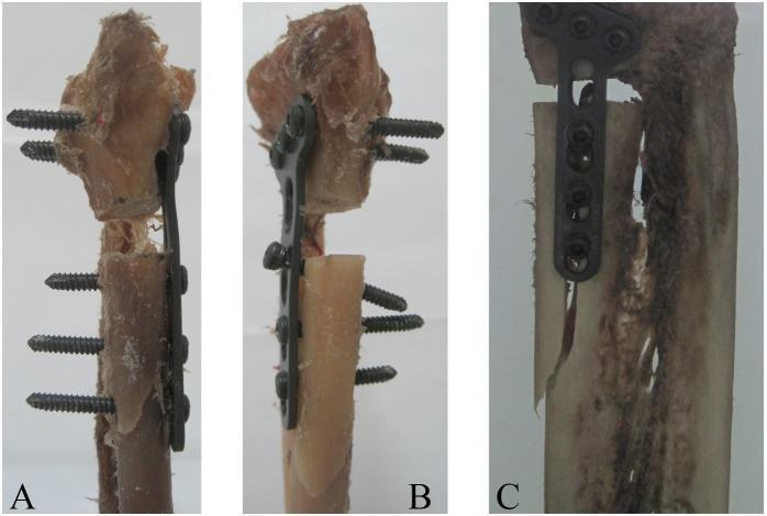
Clinical photograph of three anatomical bone specimens (A, B, and C) demonstrating catastrophic failure modes of distal radius volar plate fixation following biomechanical testing. The specimens show different internal fixation constructs using anatomical locking plates and screws for distal radius fractures. Image A illustrates a failure characterized by the collapse of the distal radius diaphysis at the osteotomy site and slight bending/deformation of the mid-plate. Image B shows failure through diaphyseal collapse accompanied by the uncoupling of a proximal locking screw from the plate hole, representing a mechanical breakdown of the screw-plate interface. Image C displays extensive comminution and splintering of the bone with failure occurring through secondary fractures near the implant site. These images serve as educational material for orthopedic surgery, specifically focusing on traumatology, fracture fixation stability, and the mechanical limits of volar locking distal radius plates in cadaveric models.
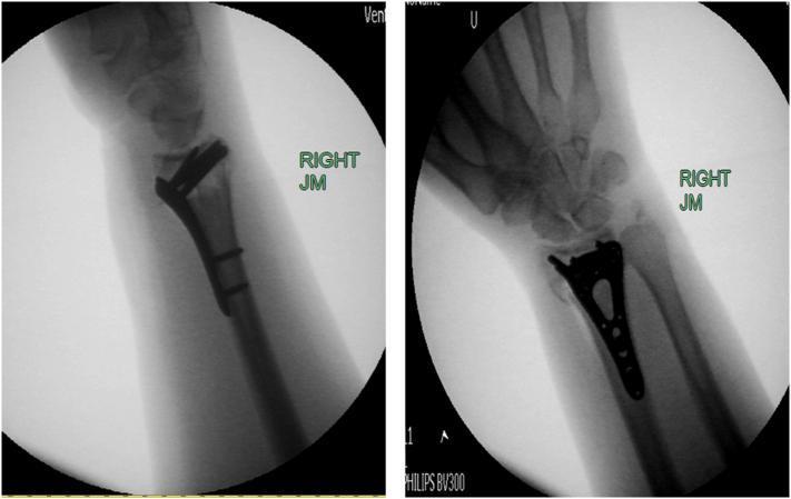
This diagnostic image consists of two intraoperative fluoroscopic films of the right wrist, demonstrating the internal fixation of a distal radius fracture. The left panel shows a lateral view where a radiopaque volar locking plate is positioned along the anterior (volar) cortex of the distal radius, spanning from the radial diaphysis to the metaphysis. The plate's contour follows the anatomical curve of the radial neck. The right panel shows an anteroposterior (AP) view, highlighting the triangular, anatomically shaped distal portion of the plate. Multiple screw holes and securing screws are visible, providing stable fixation across the fracture site. The radiocarpal joint is visualized, showing the alignment between the distal radius and the proximal carpal row (scaphoid and lunate). These images illustrate standard orthopedic surgical management for comminuted distal radius fractures using a locking plate system to maintain reduction and radial height.
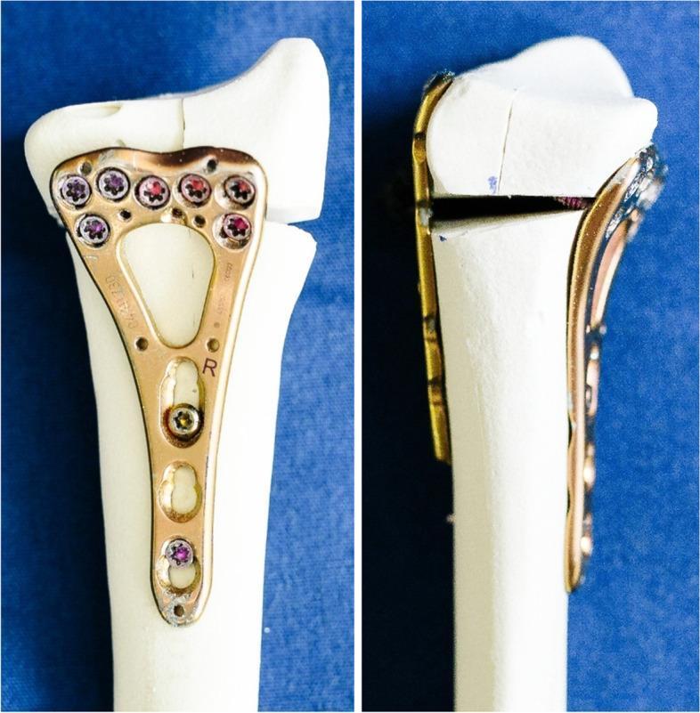
This comparative clinical imaging demonstrates internal fixation techniques for distal radius fractures using synthetic bone specimens. The image is divided into two panels: the left shows a volar locking plate (VLP) construct, and the right shows a double-plating construct. The VLP (left) is a 2.4 mm Variable Angle Locking Compression Plate (LCP) with a two-column design, anatomically contoured to the volar surface of the distal radius. It features multiple locking screws in the head to stabilize articular fragments and shaft screws for cortical fixation. The plate includes 'R' (right) and manufacturer markings. The right panel illustrates a 'sandwich' or double-plating technique, utilizing the same volar plate in conjunction with a supplemental dorsal LCP. This configuration is used to address complex intra-articular fractures with dorsal comminution, particularly involving the lunate facet. The visible osteotomy gap in the specimens simulates a clinical fracture. These constructs highlight orthopedic strategies for achieving rigid stability in distal radius osteosynthesis, emphasizing the difference between standard single-plate volar fixation and dual-plate stabilization for multi-fragmentary fractures.
Volar Plate Fixation for Distal End Radius Fractures
Overview
- Campbell's Operative Orthopaedics 15th Ed 2026, p. 3643
- Rockwood and Green's Fractures in Adults 10th Ed 2025, p. 1833
Design Features
1. Shaft (Proximal) Portion
- Contains an oblong/gliding hole inserted first to allow proximal-distal adjustment before final seating
- Subsequent holes accept standard cortical screws for shaft fixation
- Low-profile design to minimize soft tissue irritation
2. Distal (Head) Portion
- Anatomically contoured to match the volar surface of the distal radial metaphysis
- Contains multiple fixed-angle locking screw holes directed toward the subchondral bone of the articular surface
- Allows capture of small articular fragments (radial styloid, lunate facet, dorsal wall)
- Some systems use variable-angle (polyaxial) locking holes for greater flexibility in screw trajectory
- A 2.4 mm Variable Angle LCP design is one common configuration
Indications
| Fracture Type | Suitability |
|---|---|
| Displaced, unstable extra-articular fracture | Primary indication |
| Intra-articular fractures (AO/OTA Type B, C) | Standard indication |
| Volar Barton fracture | Ideal (plate directly buttresses the fragment) |
| Dorsally displaced (Colles-type) | Most common use |
| Volarly displaced (Smith's-type) | Buttress role |
| High-demand patients, bilateral injuries | Preferred for early mobilization |
The "Watershed Line" - Critical Positioning Concept
- Placement distal to the watershed line causes the plate to tent up the flexor tendons, leading to flexor tendon irritation and rupture (most commonly the FPL tendon)
- A low-profile plate at the correct level minimizes this risk
- To check: on a true lateral fluoroscopic view, the distal edge of the plate should not project beyond the volar rim of the articular surface
Surgical Technique (Chung et al. / Henry Approach)
- An 8 cm incision is made over the forearm between the radial artery and the flexor carpi radialis (FCR). A radial extension at the wrist crease is sometimes added to widen exposure.
- The FCR is retracted radially to expose the tendon subsheath. The subsheath is opened and the forearm deep fascia is incised to expose the flexor pollicis longus (FPL) and pronator quadratus.
- The FPL is swept ulnarly. The FPL muscle belly is partially detached on its radial margin to expose the pronator quadratus.
- An L-shaped incision is made in the transitional fibrous zone at the distal pronator quadratus, elevating it from the radial metaphysis to expose the entire fracture line.
Post-Operative Protocol
- MCP joints are left free; finger mobilization begins immediately
- Wrist immobilization is discontinued at 2 weeks with transition to a removable splint
- Gentle wrist motion begins at 2 weeks
- If DRUJ instability or poor bone stock is present, a cast is maintained for 6 weeks
Complications
| Complication | Notes |
|---|---|
| Flexor tendon irritation/rupture | Most common; FPL most at risk; caused by plate distal to watershed line or prominent screws |
| Extensor tendon rupture (EPL) | From dorsal screw penetration; managed with hardware removal + tendon transfer |
| Loss of reduction | Reported in up to 30%; most often involves the lunate facet |
| Carpal tunnel syndrome | Less common |
| Complex Regional Pain Syndrome (CRPS) | Uncommon |
| Infection | Rare with proper technique |
Why Volar Rather Than Dorsal?
- The volar surface is anatomically flat and provides a stable surface for plate application
- The volar approach avoids the extensor tendons (which are more at risk on the dorsal surface)
- Biomechanical studies show volar plating is superior to dorsal plating, external fixation, and percutaneous pinning for functional outcomes
- First-generation dorsal plates had unacceptably high rates of dorsal tenosynovitis
Visual Reference
- Campbell's Operative Orthopaedics 15th Ed 2026, pp. 3642-3646 (Technique 62.17, Chung et al.)
- Rockwood and Green's Fractures in Adults 10th Ed 2025, pp. 1833-1840