
Implants in orthopedic Screws plates nails In details Drill bit
Reading File
Now I'll search the medical library and web in parallel for orthopedic implants content.
Finding Sources
Finding Sources
Searching the Web
orthopedic implants screws plates intramedullary nails drill bits types details
Finding Sources
Finding Sources
Reading Web Page
https://mss-ijmsr.com/orthopedic-hardware-in-trauma-a-guided…
Reading File
Finding Sources
Finding Sources
Reading File
Searching the Web
orthopedic drill bit types sizes bone surgery AO technique cortical cancellous
Reading File
Loading Image
Reading File
Loading Image
Now I have enough rich material from Rockwood & Green's (2025) and Campbell's Operative Orthopaedics (2026) to write a comprehensive, well-illustrated answer.
Orthopedic Implants: Screws, Plates, Nails, and Drill Bits
1. OVERVIEW
Orthopedic implants are devices used to fix fractures, stabilize joints, and reconstruct bones. The fundamental goal is to reduce a fracture and fix it rigidly enough to allow healing. Internal fixators include screws, plates, intramedullary nails, rods, wires, and pins.
Materials used:
- Stainless steel - historically dominant; used in plates, sliding hip screws, some flexible nails
- Titanium alloy - preferred today for most IM nails, femoral stems; modulus closer to bone, higher fatigue strength, better MRI compatibility
- Cobalt-chromium - used in joint replacement bearings
2. SCREWS
Screws are the most commonly implanted orthopedic device. Every screw shares the same basic anatomy:
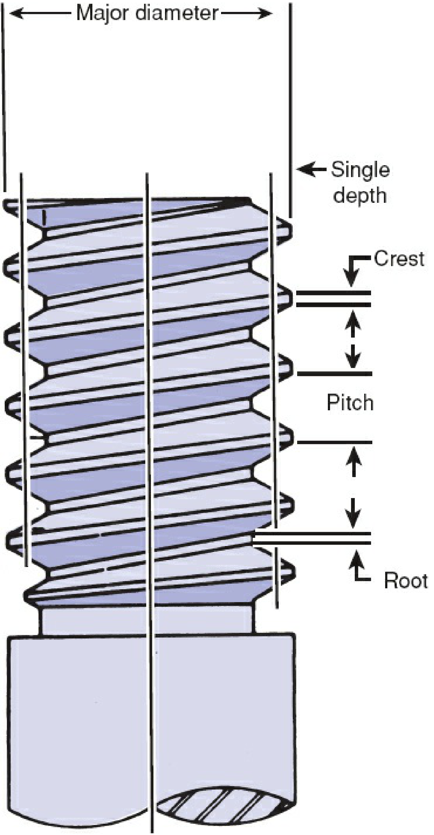
Screw Anatomy (from Rockwood & Green 10th Ed, 2025)
| Part | Description |
|---|---|
| Head | Engages the screwdriver; acts as a buttress to compress plate/bone |
| Shaft | Inner (core/minor) + outer (thread/major) diameter |
| Threads | Flat surfaces providing purchase; thread depth = (major - minor) / 2 |
| Tip | Self-tapping flutes or plain; 4 cutting flutes = best insertion + holding power |
| Pitch | Distance between threads; smaller pitch = finer threads = more purchase per length |
The minor (core) diameter determines bending strength. The thread depth and pitch together determine stripping torque (max torque before threads strip from bone).
Types of Screws by Bone Type
A. Cortical Screws
- Used in: Dense diaphyseal (shaft) cortical bone
- Design: Small pitch, shallow thread depth
- Sizes: Typically 3.5 mm, 4.5 mm (large fragment); 2.7 mm, 2.0 mm (small fragment)
- Drill bit used = minor (core) diameter of screw
B. Cancellous Screws
- Used in: Metaphyseal/epiphyseal cancellous (spongy) bone
- Design: Large pitch, deep thread depth to maximize purchase in porous bone
- Sizes: 4.0 mm (small), 6.5 mm / 7.3 mm (large, used in femoral neck)
- Can be fully threaded or partially threaded
C. Malleolar Screws
- Used specifically for ankle fracture fixation (medial malleolus)
- Features a larger head and partially threaded shaft
Types of Screws by Function
| Type | Mechanism | Use |
|---|---|---|
| Lag screw | Threads only in far fragment; head compresses near fragment toward far = interfragmentary compression | Articular fractures, simple patterns requiring absolute stability |
| Position screw | Full thread both fragments; holds position without compression | Syndesmosis fixation, talocrural joint |
| Locking screw | Threaded head locks into plate hole; creates fixed-angle construct | Osteoporotic bone, periarticular fractures |
| Cannulated screw | Hollow core threaded over K-wire (Seldinger technique) | Hip fracture fixation (femoral neck), precision under fluoroscopy |
| Neutralization screw | Placed through plate to protect lag screws from torsion and bending | Used in combination with lag screws |
| Compression screw | Generates compression (e.g., DHS - Dynamic Hip Screw) | Intertrochanteric femur fractures |
| Poller (blocking) screw | Placed adjacent to nail to guide nail path | IM nailing of distal/proximal fractures |
| Anchor screw | Post for wires/sutures | Tension band wiring |
| Interlocking screw | Locks IM nail proximally and distally | Prevents rotation and shortening of nailed fractures |
Lag Screw Technique (detailed)
Lagging by technique:
- Drill a glide hole in near fragment = same diameter as screw's major (thread) diameter
- Use a "top-hat" drill guide to drill a pilot hole in far fragment = minor (core) diameter
- As screw advances, threads bite only the far fragment; head compresses near fragment = interfragmentary compression
- Both holes must be co-linear and perpendicular to fracture line for maximal compression
Lagging by design (partially threaded):
- Thread-free shaft glides through near fragment automatically
- Used for cancellous lag screws (e.g., 6.5 mm cancellous across femoral neck)
Tapping
A tap is a device with the same diameter and thread profile as the screw, with sharp flutes that precut the bone channel. Reduces friction, protecting small screws from breaking. Most modern screws are self-tapping (cutting flutes on tip). In dense bone (e.g., femoral neck in young patients with sliding hip screw), manual tapping may be needed to prevent femoral head rotation during insertion.
Bicortical vs. Unicortical Screws
- Bicortical: Penetrate both cortices; better purchase, greater pullout resistance - standard for diaphyseal plating
- Unicortical: Remain in proximal cortex only; used in locking plate systems; less stress shielding, lower refracture risk on removal
3. PLATES
Plates were first used for long bone fractures in 1886. Today they are the standard for many periarticular and diaphyseal fractures.
Types of Plates by Function
A. Dynamic Compression Plate (DCP) / LC-DCP
- Oval "load-screw holes" with an inclined ramp
- As a screw is tightened eccentrically in the hole, the plate slides and generates compression at the fracture site
- Used for transverse/short oblique diaphyseal fractures requiring absolute stability
- Primary bone healing (Haversian remodeling) expected - no visible callus
B. Locking Compression Plate (LCP)
- Combination holes accept both standard screws (compression mode) and locking screws (angle-stable mode)
- Locking screws have threaded heads that lock into the plate, creating a fixed-angle construct
- The plate does NOT need to contact bone - acts as an internal fixator
- Does not rely on plate-to-bone friction = works in osteoporotic bone where conventional screws pull out
- Single most important innovation in fracture fixation in the last 30 years
C. Buttress Plate
- Undercontoured plate applied at vertically oriented partial articular fractures
- Prevents axial collapse; an "axillary screw" in the stable segment generates compression
- Used at: distal radius, proximal tibia, posterior malleolus (distal tibia)
- Produces absolute stability = primary bone healing
D. Antiglide Plate
- Prevents shortening (shearing) in oblique fractures
- Does not necessarily apply compression (distinguishes it from buttress)
- Classic use: posterior/posterolateral plating of distal fibula
E. Bridge Plate
- Used for highly comminuted fractures where screw purchase across all fragments is not possible
- Spans the comminuted zone; screws only in proximal and distal intact segments
- Provides relative stability = secondary bone healing with callus formation
F. Tension Band Plate
- Applied to the convex (tension) surface of an eccentrically loaded bone
- Converts tensile forces to compressive forces
- Used at: olecranon (proximal ulna), patella
- Only appropriate for transverse fracture patterns with an intact concave surface
G. Neutralization Plate
- Plate spans the fracture but doesn't generate compression itself
- Protects lag screws from torsion, bending, shear
- Common in oblique/spiral fractures of tibia, fibula, forearm
H. Reconstruction Plate
- Highly malleable; can be contoured in three planes
- Used for complex pelvic/acetabular fractures, mandible, clavicle
Small Fragment vs. Large Fragment Sets
- Small fragment: Screws 2.0-3.5 mm, for small bones (distal fibula, hand)
- Large fragment: Screws 4.5-6.5 mm, for large bones (femur, tibia, humerus)
4. INTRAMEDULLARY (IM) NAILS
IM nails are inserted into the medullary (central) canal of long bones. They are the standard of care for femoral and tibial shaft fractures.
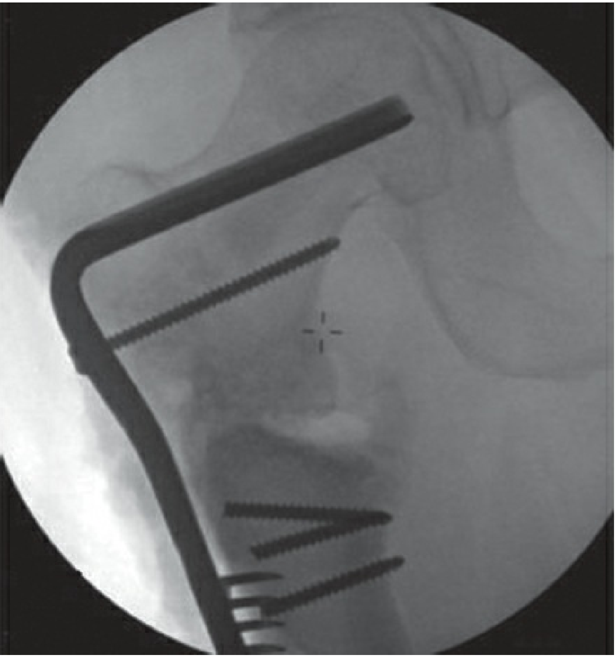
Types of IM Nails
| Type | Description | Use |
|---|---|---|
| Rigid IM nail (antegrade) | Inserted from proximal end (e.g., piriform fossa or greater trochanter for femur) | Femoral shaft fractures |
| Retrograde IM nail | Inserted from distal end (knee) | Distal femur, periprosthetic, obese patients |
| Cephalomedullary nail | Proximal screw/blade into femoral head/neck + IM nail body | Intertrochanteric and subtrochanteric fractures |
| Tibial IM nail | Inserted through patellar tendon or parapatellar | Tibial shaft fractures |
| Humeral IM nail | Antegrade (shoulder) or retrograde (elbow) | Humeral shaft fractures |
| Flexible (elastic) nail | TENS (Titanium Elastic Nailing System) - multiple flexible nails | Pediatric fractures; does NOT require reaming |
| Antibiotic cement nail | IM cement spacer with antibiotics | Infected nonunion, osteomyelitis staged treatment |
Key Design Features
Solid vs. Cannulated
- Solid nails: Stronger in torsion
- Cannulated (hollow) nails: More flexible, conform to canal shape, easier insertion; most modern nails are cannulated to allow insertion over a guide wire
Reamed vs. Unreamed
- Reamed: Progressively larger reamers prepare the canal; allows larger diameter nail = stronger construct
- Unreamed: Preserves endosteal blood supply; used in contaminated wounds or high-energy open fractures
Interlocking Screws
- Placed at proximal and distal ends to prevent rotation and shortening
- Static locking: Both ends locked (for comminuted, length-unstable fractures)
- Dynamic locking: One end unlocked to allow controlled axial compression with weight-bearing
Working Length
- The distance between the most proximal and distal fixation points
- Longer working length = more flexible construct, greater relative motion, secondary bone healing
- Shorter working length = stiffer construct
Biomechanics
- Bending stiffness increases with the square of nail radius (r²)
- Bending stiffness inversely proportional to the square of working length
- Modern nails are titanium alloy (modulus closer to bone than stainless steel; higher fatigue strength)
- Anatomically pre-curved to match the anterior bow of the femur or tibia
5. DRILL BITS IN ORTHOPEDIC SURGERY
Drill bits are used to create the bone channels (pilot holes and glide holes) needed before screw insertion.
Structure of an Orthopedic Drill Bit
- Flutes - helical cutting edges that remove bone debris; 2-4 flutes common
- 4-flute bits = easier insertion + greater holding power
- Tip - pointed cutting tip; most are twist (spiral) design
- Shank - the non-cutting end that connects to the power drill
- Jacobs chuck (round) shank - universal fit
- SQC (Standard Quick Connect) shank - snap-in/out, used in most modern orthopedic power tools
- Cannulated - hollow core allowing placement over a K-wire (used with cannulated screws)
- Non-cannulated - solid; general purpose
Drill Bit Types
| Type | Description | Use |
|---|---|---|
| Jacobs Twist | Round shank, double-fluted | General purpose, manual or power drill |
| SQC (Standard Quick Connect) | Quick-release snap-in shank | Modern power drills, most common intraoperatively |
| Cannulated | Hollow center; threaded over K-wire | Cannulated screw systems, hip fracture fixation |
| Stepped / Countersink | Creates a countersunk recess | Prevents screw head prominence, reduces near cortex crack risk |
Key Drill Bit Sizes (AO/Synthes Standard)
The drill bit diameter chosen depends on whether you are creating a glide hole or a pilot (threaded) hole:
| Screw Diameter | Glide Hole Drill (= major/thread diameter) | Pilot Hole Drill (= minor/core diameter) |
|---|---|---|
| 2.0 mm cortical | 2.0 mm | 1.5 mm |
| 2.7 mm cortical | 2.7 mm | 2.0 mm |
| 3.5 mm cortical | 3.5 mm | 2.5 mm |
| 4.5 mm cortical | 4.5 mm | 3.2 mm |
| 6.5 mm cancellous | 6.5 mm | 3.2 mm |
| 7.3 mm cannulated | 7.3 mm | -- (over guidewire) |
Practical Drill Technique Rules
- Use a drill sleeve / tissue protector to protect soft tissues and maintain axial alignment
- Use slow speed (500-1000 rpm) in cortical bone to prevent thermal necrosis (bone dies above 47°C)
- Use irrigation (saline) or intermittent drilling to reduce heat generation
- Perpendicular to fracture line for maximum lag screw compression
- Do NOT force the drill - let the bit do the work; excessive pressure blunts flutes and increases heat
- 4-flute bits are preferred over 2-flute for better torque distribution and debris clearance
- After drilling, measure depth with a depth gauge to select correct screw length
- In dense bone, follow drilling with tapping before screw insertion
Thermal Necrosis Risk
Excessive heat from drilling causes osteocyte death and impairs healing. Factors that increase heat:
- High RPM
- Blunt/dull drill bit
- No irrigation
- Heavy axial pressure
- Dense cortical bone
6. SUMMARY TABLE
| Implant | Primary Mechanism | Material | Common Indications |
|---|---|---|---|
| Cortical screw (3.5/4.5 mm) | Compression via threads in cortex | SS or Ti | Plate fixation, diaphyseal fractures |
| Cancellous screw (6.5/7.3 mm) | Broad threads in cancellous bone | SS or Ti | Femoral neck, metaphyseal fractures |
| Cannulated screw | Placed over guidewire | Ti alloy | Hip fracture (femoral neck) |
| Locking screw | Fixed-angle plate-screw construct | Ti alloy | Osteoporotic bone, periarticular |
| DCP/LC-DCP | Dynamic interfragmentary compression | SS or Ti | Diaphyseal transverse/oblique fractures |
| LCP | Fixed-angle internal fixator | Ti alloy | Osteoporotic/periarticular fractures |
| Bridge plate | Spans comminution zone | Ti alloy | Comminuted fractures |
| Rigid IM nail | Load-sharing intramedullary | Ti alloy | Femur/tibia/humerus shaft fractures |
| Cephalomedullary nail | IM + cephalic element | Ti alloy | Intertrochanteric hip fractures |
| TENS flexible nail | Multiple elastic nails | Ti alloy | Pediatric long bone fractures |
Sources:
- Rockwood & Green's Fractures in Adults, 10th Ed 2025, Chapter 12 (Implants and Biomechanics), pp. 471-491
- Campbell's Operative Orthopaedics, 15th Ed 2026 - multiple chapters on fracture fixation techniques
- Indian J Musculoskeletal Radiology - Orthopedic Hardware in Trauma
- AO Surgery Reference - Lag Screw Technique
This is a shared conversation. Sign in to Orris to start your own chat.