
Step by step procedure of evar
EVAR endovascular aneurysm repair stent graft deployment procedure
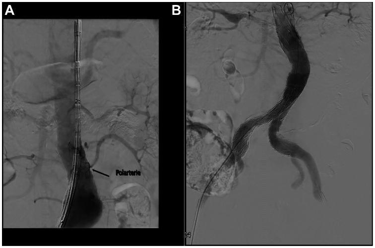
This composite of two diagnostic angiograms (A and B) illustrates a standard Endovascular Aneurysm Repair (EVAR) procedure for an infrarenal abdominal aortic aneurysm. Image A displays the pre-deployment or intra-procedural phase, showing a catheter and stent-graft delivery system positioned within the abdominal aorta. A black arrow labeled 'Polarterie' indicates the presence of a left accessory renal artery (ARA) that is anatomically situated within the landing zone of the graft, highlighting the challenge of unintentional vessel coverage during repair. Image B shows the successful post-deployment of a bifurcated stent-graft. The device exhibits a characteristic metallic stent skeleton with a woven graft material, forming a main body in the aorta that bifurcates into two iliac limbs to maintain distal perfusion. The image demonstrates proper graft apposition and exclusion of the aneurysmal sac, with no visible endoleaks. This content is relevant for vascular surgery and radiology education regarding aortic anatomy, graft selection, and the management of accessory renal vessels during EVAR.
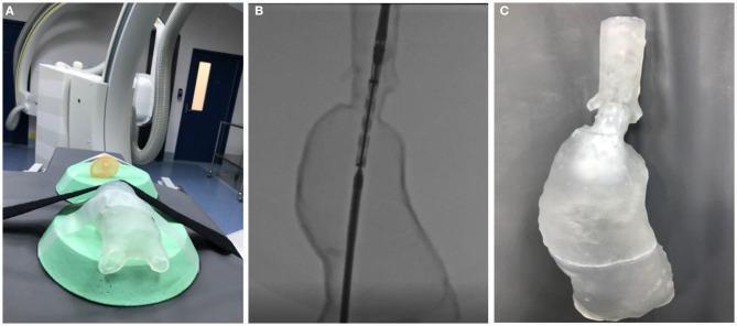
This composite image illustrates the application of 3D printing in vascular surgery simulation, specifically for abdominal aortic aneurysm (AAA) repair. Panel A shows a transparent, 3D-printed AAA phantom, manufactured using Stereolithography (SLA) resin, positioned on a clinical fluoroscopy table in preparation for an endovascular procedure simulation. Panel B displays a fluoroscopic diagnostic image of the same phantom, demonstrating its radiolucency and the high-contrast visualization of an intravascular catheter and a developing stent graft. This highlights the model's utility in mimicking real-time intraoperative imaging. Panel C presents the post-procedural model, showcasing the successful deployment of a fenestrated stent graft within the transparent aneurysm sac. The series demonstrates the process of using patient-specific vascular models for preoperative planning and simulation of complex fenestrated endovascular aneurysm repair (EVAR), facilitating anatomical insight and procedural practice in a risk-free environment.
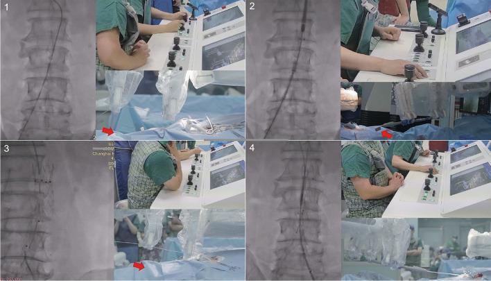
This composite clinical figure illustrates four key stages of a robotic-assisted Endovascular Aortic Repair (EVAR) for an abdominal aortic aneurysm. Each quadrant (1–4) combines real-time fluoroscopic imaging of the lumbar spine and vasculature with photographs of the operator's remote console and the robotic functional unit at the patient's bedside.

A side-by-side comparison of two diagnostic imaging modalities used during endovascular aneurysm repair (EVAR) for an infrarenal abdominal aortic aneurysm. Image (a) is an intraoperative fluoroscopic frame from a digital subtraction angiography (DSA) procedure. It shows a grayscale anteroposterior view of the lumbar vertebral column with a radiopaque catheter and pigtail markers visible. The pigtail markers are spaced at 10mm intervals for calibration. Image (b) shows a preoperative computed tomography angiography (CTA) scan converted into a digital X-ray projection (DRR) through automated segmentation. The vertebral bodies in the DRR appear with higher contrast and more sharply defined cortical edges compared to the live fluoroscopy. The comparison illustrates the process of automated image fusion, where the skeletal landmarks from the preoperative CTA are registered and superimposed onto the real-time fluoroscopic field to improve vascular alignment and surgical precision during stent-graft deployment.
EVAR endovascular aneurysm repair step by step procedure surgical technique
EVAR (Endovascular Aneurysm Repair) - Step-by-Step Procedure
Phase 1: Preoperative Planning
-
CT Angiography (CTA) assessment - Detailed imaging of the aorta to measure:
- Aneurysm diameter, length, and neck morphology
- Distance from the renal arteries to the aneurysm neck (infrarenal landing zone)
- Iliac artery diameter and tortuosity (access vessel suitability)
- Presence of accessory renal arteries within the landing zone
-
Device selection - Based on CTA measurements, a bifurcated stent-graft is chosen (main body + two iliac limbs). Fenestrated or branched devices may be required if the aneurysm is near visceral vessels.
-
Patient preparation:
- Antiplatelet therapy review (aspirin typically continued)
- Renal function optimized (IV hydration pre/post-procedure to reduce contrast nephropathy)
- Prophylactic antibiotics given before the procedure
Phase 2: Anesthesia and Positioning
-
Anesthesia - General, regional (epidural/spinal), or even local anesthesia can be used. EVAR is particularly valuable in high-risk patients who poorly tolerate general anesthesia. The patient is placed supine.
-
Fluoroscopic suite setup - Procedure is performed in a hybrid operating room or angiography suite with a C-arm or fixed fluoroscopy system and digital subtraction angiography (DSA) capability.
Phase 3: Vascular Access
-
Bilateral femoral artery access - Two approaches exist:
- Open cut-down: A 4-6 cm surgical incision is made over each common femoral artery in the groin, exposing the vessel under direct vision.
- Percutaneous EVAR (PEVAR): Sub-centimeter skin punctures using the Seldinger technique, followed by pre-closure with suture-mediated devices (e.g., Perclose ProGlide) placed before large-bore sheaths are inserted.
-
Sheath insertion - After arterial access is confirmed, vascular sheaths (typically 6-Fr initially) are introduced over guidewires bilaterally.
-
Systemic heparinization - Unfractionated heparin is administered intravenously (typically 70-100 units/kg) to achieve an ACT >250 seconds, preventing thrombus formation during device manipulation.
Phase 4: Diagnostic Angiography
-
Pigtail catheter placement - A calibrated pigtail catheter (with radio-opaque markers at 10 mm intervals) is advanced via one femoral sheath and positioned above the renal arteries (typically at L1 level).
-
Pre-deployment angiogram - Contrast is injected to identify:
- The exact level of both renal arteries
- Celiac and superior mesenteric artery origins
- The aortic bifurcation and iliac anatomy
- Any variant anatomy (accessory renal arteries, hypogastric arteries)
- Lumbar vertebral landmarks for fluoroscopic reference during deployment
Phase 5: Main Body Deployment
-
Stiff guidewire placement - A stiff exchange-length guidewire (e.g., Lunderquist or Amplatz Super Stiff) is advanced through the ipsilateral (main body side) femoral access up through the aneurysm and into the descending thoracic aorta.
-
Large-bore sheath insertion - The 6-Fr sheath is exchanged for a large-bore delivery sheath (typically 18-24 Fr depending on device) over the stiff wire. This creates the conduit for the main body device.
-
Main body advancement - The folded stent-graft (loaded within the delivery system) is advanced carefully through the iliac artery into the aorta under continuous fluoroscopic guidance.
-
Precise positioning - The proximal end of the graft (proximal neck) is aligned just below (infrarenal) the lowest renal artery, confirmed by fluoroscopy and repeat DSA. The deployment marker on the device must be at the level of the lowest renal artery ostium.
-
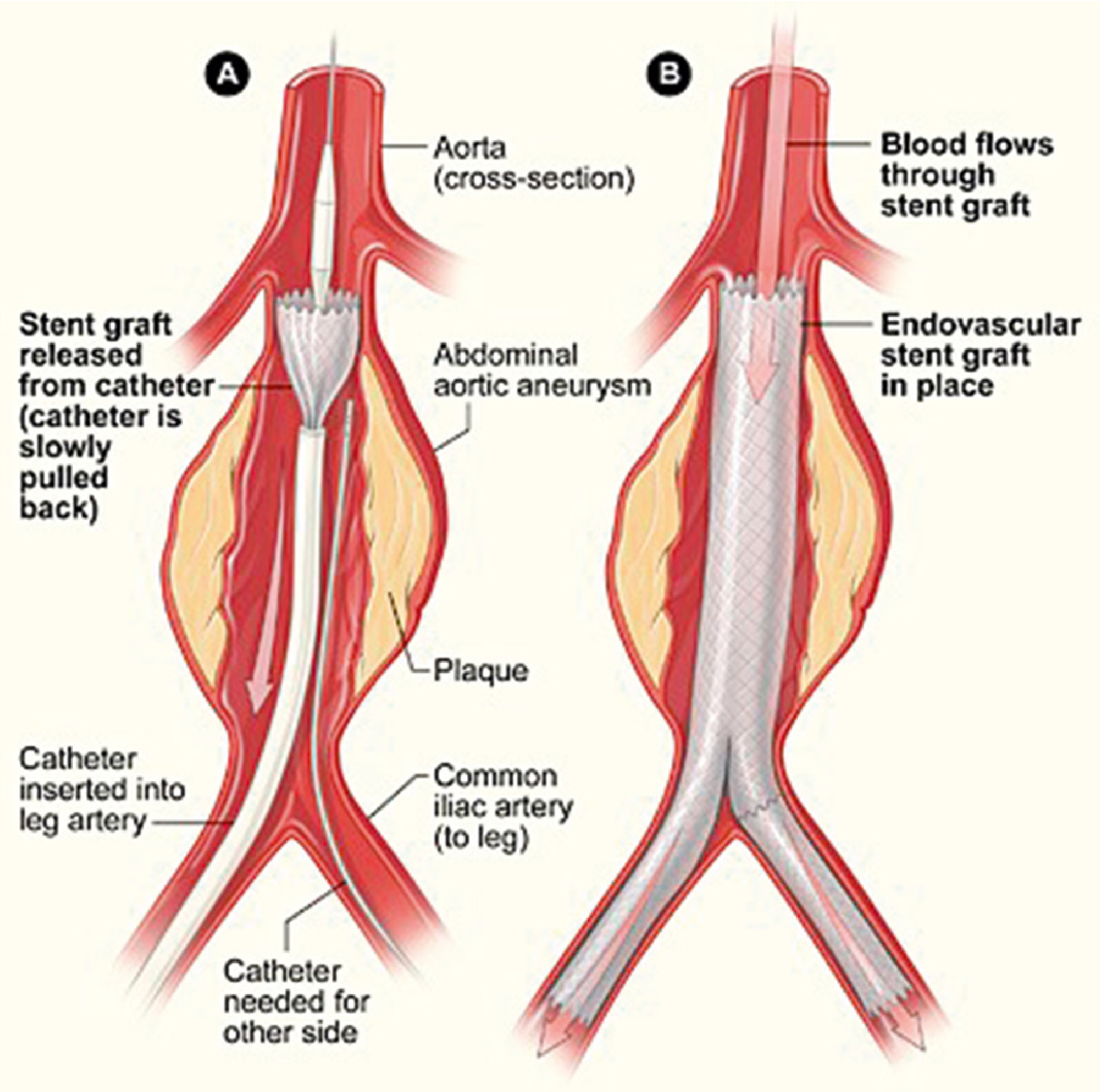
Main body release - The outer sheath of the delivery system is retracted (or a trigger mechanism is used, device-dependent), allowing the stent-graft to self-expand and deploy from proximal to distal. The main body seals against the infrarenal aortic neck.
Phase 6: Contralateral Limb Cannulation
-
Contralateral gate cannulation - This is often the most technically challenging step. A guidewire and catheter are advanced from the contralateral (opposite) femoral access and directed into the short contralateral gate/limb of the main body device. Fluoroscopy, rotation, and angled projections help locate the gate. Snare techniques may be used if cannulation is difficult.
-
Contralateral limb deployment - Once the gate is cannulated and wire position confirmed by DSA, the contralateral iliac limb extension is advanced and deployed, creating the bifurcated configuration and sealing distally into the common iliac artery.
Phase 7: Ipsilateral Iliac Limb
- Ipsilateral limb extension - The ipsilateral iliac limb (docking limb) is deployed from the main body down into the ipsilateral common iliac artery, with appropriate overlap between components to prevent type III endoleak.
Phase 8: Balloon Molding
-
Proximal neck ballooning - A compliant aortic balloon (e.g., Coda balloon) is inflated within the proximal neck of the graft to ensure full apposition and sealing between the graft fabric and the aortic wall, eliminating type I endoleak risk.
-
Overlap zone ballooning - Balloon molding is repeated at component overlap zones (proximal neck, limb-to-body connections) to fully expand and seat the graft.
Phase 9: Completion Angiogram
-
Final DSA - A completion angiogram is performed with contrast injected via the pigtail catheter to confirm:
- Both renal arteries are patent and not covered
- Both iliac limbs are widely patent
- No endoleak (particularly Type I - proximal/distal seal zone leak, or Type III - component junction leak)
- No limb kinking or occlusion
-
Additional interventions if needed - If a Type I endoleak is identified, proximal extension cuffs or additional balloon dilation are performed. Type II endoleaks (from back-bleeding lumbar or inferior mesenteric arteries) are often observed initially.
Phase 10: Access Site Closure
-
Device removal - All delivery systems, catheters, and guidewires are removed sequentially.
-
Arteriotomy closure:
- Open cut-down: Surgical repair of the femoral arteriotomy with prolene suture under direct vision.
- PEVAR: The pre-placed suture-mediated closure devices (ProGlide knots) are cinched down to achieve hemostasis. Manual compression is applied if residual bleeding occurs. A third ProGlide may be deployed if needed.
-
Hemostasis confirmation - Bilateral femoral pulses are palpated and confirmed before leaving the operating room.
Phase 11: Post-Procedure Care
-
Recovery monitoring - Bilateral lower extremity pulses and neurological status (watch for spinal cord ischemia, especially in TEVAR) are closely monitored.
-
Hydration - IV fluids to maintain renal perfusion and promote contrast clearance; serial creatinine monitoring.
-
Surveillance imaging - CTA at 1 month, 6 months, and annually thereafter to detect:
- Endoleak (especially late-onset Type I or III)
- Sac expansion
- Device migration or structural failure
- Limb thrombosis
Summary Table
| Step | Action |
|---|---|
| Pre-op | CTA planning, device selection |
| Access | Bilateral femoral cut-down or PEVAR |
| Angiography | Pigtail catheter, renal artery identification |
| Main body | Stiff wire, large-bore sheath, deploy below renal aa. |
| Contralateral limb | Cannulate gate, deploy iliac limb |
| Ipsilateral limb | Deploy docking limb |
| Molding | Balloon proximal neck + overlaps |
| Completion DSA | Confirm no endoleak, renal patency |
| Closure | Suture or ProGlide closure |
| Post-op | Pulses, renal function, annual surveillance CTA |
Key Complications to Watch For
-
Endoleak (most common): Type I (proximal/distal seal failure), Type II (collateral back-fill), Type III (component separation), Type IV (graft porosity)
-
Limb thrombosis / occlusion
-
Renal artery coverage - inadvertent coverage causing acute kidney injury
-
Access site complications - hematoma, pseudoaneurysm, lymphocele
-
Spinal cord ischemia (more relevant in TEVAR)
-
Contrast nephropathy
-
Late device migration or structural failure - reason for lifelong surveillance
-
Schwartz's Principles of Surgery, 11th Ed.
-
Miller's Anesthesia, 10th Ed.
-