
Anal canal
anal canal anatomy diagram
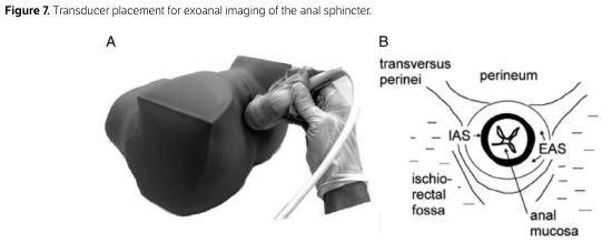
Summary : This figure demonstrates the placement of an ultrasound transducer for exoanal imaging of the anal sphincter, including both a photographic representation and a schematic cross-sectional diagram of the relevant anatomy.
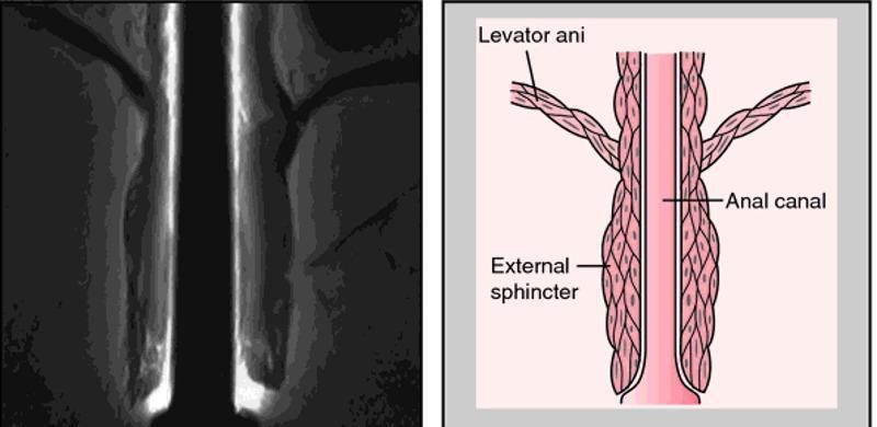
A composite image for medical education comprising a diagnostic radiological image (MRI) on the left and a corresponding anatomical diagram on the right, illustrating the pelvic floor and anal canal. The MRI shows a coronal view of the anorectal region, highlighting the muscular layers of the pelvic outlet. The anatomical diagram provides a schematic representation of the same structures for clarity. It labels the levator ani as a broad, striated muscle group superiorly that forms the pelvic diaphragm and descends to blend with the longitudinal muscle layer of the anal canal. The external sphincter is depicted as a distinct, thicker muscular cuff surrounding the distal portion of the anal canal, located inferior to the levator ani's main attachment points. This visual comparison is designed to teach the spatial relationships between the pelvic floor muscles and the terminal digestive tract, emphasizing the functional anatomy required for fecal continence. The educational focus is on identifying the levator ani and external sphincter during pelvic imaging and understanding their relative morphology.
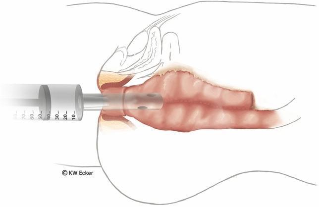
Anatomical diagram in longitudinal section depicting a surgical bubble test following an ileal pouch-anal anastomosis (IPAA). The illustration shows a soft ileostomy catheter inserted transanally through the anal canal and internal/external sphincter complex into the distal aspect of an ileal J-pouch. The catheter tip features multiple side-perforations to facilitate air insufflation. A large-volume syringe (approximately 70 ml capacity, with the plunger positioned near the 40-50 ml mark) is attached to the external end of the catheter. The visual highlights the relationship between the newly constructed anastomosis line and the transanal instrumentation. This diagnostic maneuver is used intraoperatively to identify potential anastomotic leaks by observing for air bubbles in a saline-filled pelvis. The diagram emphasizes key structures including the rectal cuff, the pouch-anal junction, and the surrounding pelvic floor anatomy in the context of colorectal surgery and fecal diversion management.
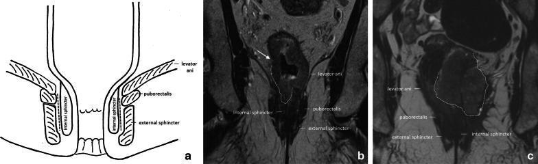
This composite educational image illustrates the pelvic floor and anal canal anatomy and its clinical relevance in rectal cancer staging. Panel (a) is an anatomical diagram depicting the coronal view of the anal canal, highlighting the levator ani, puborectalis muscle, external sphincter, and internal sphincter, with a dashed line marking the intersphincteric plane. Panel (b) is a coronal T2-weighted MRI showing a cT3a rectal tumor in a male patient. An arrow indicates irregular wall thickening with minimal (±1 mm) perirectal extension invading the right internal anal sphincter. Panel (c) is a coronal T2-weighted MRI of a female patient with a cT4b rectal tumor. The tumor (outlined by a dashed line) shows extensive infiltration, invading both internal sphincters and extending into the external sphincter, levator ani, and puborectalis muscles on the left side. Muscles and sphincters appear characteristically hypointense on T2 imaging, while the tumor presents as an intermediate-signal mass disrupting normal anatomical boundaries, essential for determining surgical management such as abdominoperineal resection.
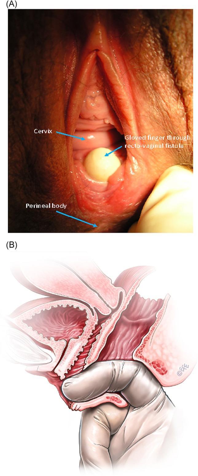
The image consists of two parts illustrating a low rectovaginal fistula (RVaF). Figure A is a clinical photograph of the perineal region showing a low-seated fistula located on the posterior vaginal wall, just proximal to the anus. A gloved finger is shown protruding through the fistula defect from the rectum into the vagina to demonstrate the abnormal communication. Key landmarks labeled include the cervix superiorly, the fistula site, and the perineal body inferiorly. Figure B is a corresponding sagittal anatomical diagram providing a schematic representation of the same condition. It illustrates the pelvic anatomy including the bladder, uterus, vagina, and rectum. The diagram highlights the fistula tract connecting the anterior wall of the rectum to the posterior vaginal wall. Similar to the photograph, it depicts a gloved finger passing through the anal canal and through the rectovaginal defect, reinforcing the diagnostic physical exam finding. This comparison is used in medical education to teach the clinical appearance and anatomical path of obstetric or acquired rectovaginal fistulas.
Anal Canal
Overview
Boundaries and Course
- Begins at the terminal end of the rectal ampulla, where the bowel narrows at the pelvic floor (anorectal junction)
- The anorectal junction sits within the pelvic diaphragm, encircled by the levator ani, coccygeus, and puborectalis muscles - their contraction maintains continence and relaxation permits defecation
- Passes inferiorly and posteriorly/outward to terminate at the anus
Sphincter Complex
- Internal anal sphincter: continuation of the circular smooth muscle layer of the bowel wall, involuntary, surrounds the upper three-quarters of the canal
- External anal sphincter: striated (skeletal) muscle, voluntary, surrounds the canal and blends its fibers with the levator ani, attaching posteriorly to the coccyx and anteriorly to the perineal body
Mucosal Landmarks (proximal to distal)
- Upper anal canal - lined by rectal-type mucosa (simple columnar epithelium)
- Anal columns (columns of Morgagni) - 6-12 longitudinal mucosal folds in the distal ~3 cm, ending distally in anal papillae
- Anal valves - crescentic folds joining the columns inferiorly, forming a ring at the pectinate (dentate) line - this marks the approximate site of the fetal cloacal membrane and the embryological hindgut/proctodeum junction
- Anal sinuses - small depressions superior to each valve (site of anal gland ducts)
- Anal pecten - transition zone inferior to the pectinate line, lined by nonkeratinized stratified squamous epithelium
- Anocutaneous line ("white line"/zona alba) - where the lining becomes true (keratinized) skin
- Anal verge - the distal transition of anoderm to perianal skin
Clinical Significance of the Dentate/Pectinate Line
| Feature | Above dentate line (hindgut) | Below dentate line (proctodeum) |
|---|---|---|
| Epithelium | Columnar | Stratified squamous |
| Arterial supply | Superior rectal (from IMA) | Inferior rectal (from internal pudendal) |
| Venous drainage | Superior rectal vein -> portal system | Inferior rectal vein -> systemic (internal iliac) |
| Lymphatic drainage | Inferior mesenteric/paraaortic nodes | Inguinal lymph nodes |
| Innervation | Autonomic (visceral, pain-insensitive) | Somatic/pudendal (pain-sensitive) |
Vascular and Lymphatic Supply
- Arterial: superior, middle, and inferior rectal (hemorrhoidal) arteries, from the inferior mesenteric, internal iliac, and internal pudendal arteries respectively
- Venous: internal hemorrhoidal plexus drains via superior rectal vein into the portal system; external hemorrhoidal plexus drains via middle rectal and pudendal veins into the internal iliac (systemic) vein
- Lymphatics: proximal to the dentate line -> inferior mesenteric/paraaortic nodes; distal to the dentate line -> inguinal lymph nodes
Illustration