
give me detalied information on total shoulder arthroplasty with its principles, biomechanics involved, classification of glenoid wear, indications, contraindications, investigations and work up, surgical techniques, cemented vs uncemented, postoperative care and complications.
total shoulder arthroplasty principles biomechanics glenoid wear classification surgical technique 2024
"shoulder arthroplasty"[MeSH Terms] AND "glenoid"[MeSH Terms]
total shoulder arthroplasty glenoid component humeral head replacement
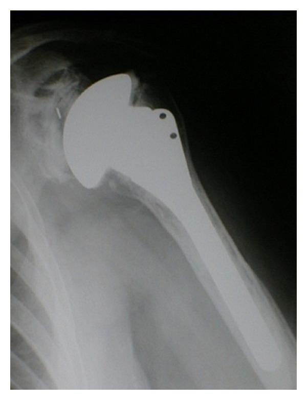
This diagnostic x-ray radiograph demonstrates a total shoulder arthroplasty (TSA). The imaging shows the proximal humerus, glenohumeral joint space, and partial scapula. The humeral component consists of a highly radiopaque metallic intramedullary stem securely positioned within the humeral shaft and a smooth, rounded prosthetic humeral head replacing the original anatomical head. Key features include the surgical replacement of the articulating surface and the visibility of orthopedic hardware, such as suture holes or screw fixations on the proximal portion of the prosthesis. The prosthetic head articulates with the glenoid fossa of the scapula, where a polyethylene glenoid component (often radiolucent but indicated by the joint spacing) is typically placed in a total arthroplasty. This image serves as a clinical example of the surgical management for advanced glenohumeral osteoarthritis, illustrating the interface between metallic implants and native bone structure for orthopedic educational purposes.
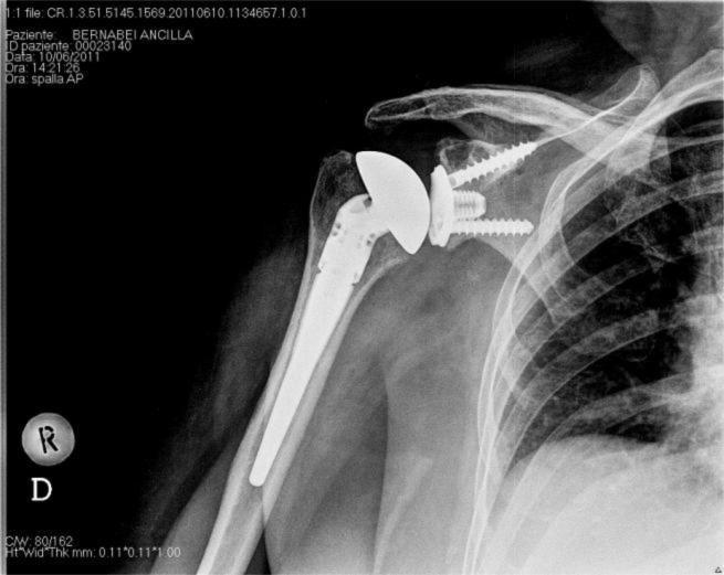
This anterior-posterior (AP) X-ray of the right shoulder demonstrates a Total Shoulder Arthroplasty (TSA). The humeral component is a stemmed metallic prosthesis with high radiopacity, extending into the medullary canal of the humerus. The proximal humeral head is replaced with a hemispherical metallic component. The glenoid component is a metal-backed design, indicated by its distinct radiopaque baseplate and visible fixation hardware. Two radiopaque cancellous screws are seen extending from the glenoid baseplate into the scapular neck to provide primary mechanical stability. A central peg or keel-like structure is also visible at the center of the glenoid component. The articulation between the humeral head and the glenoid liner appears well-maintained. This image serves as an educational example of third-generation modular shoulder prostheses and the radiographic evaluation of surgical hardware positioning, cement interfaces, and bone-implant integration.
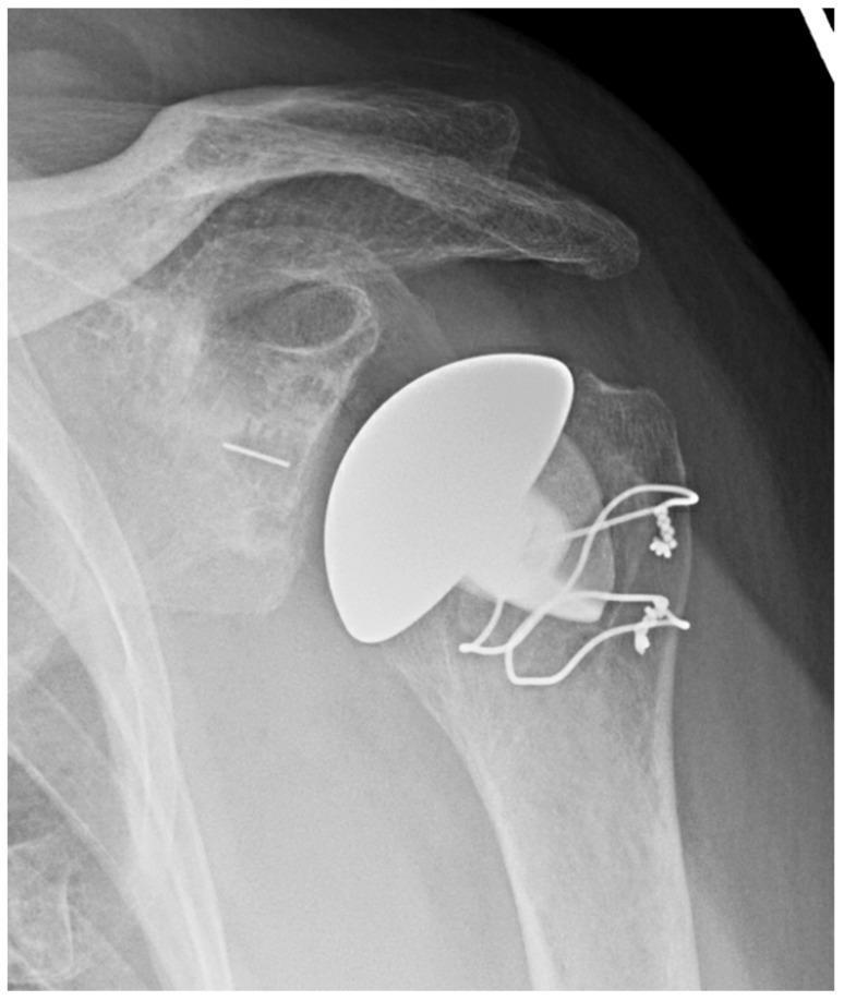
Anteroposterior (AP) radiographic view of the shoulder demonstrating a stemless anatomic Total Shoulder Arthroplasty (TSA). The humeral component is a stemless, radiopaque, bulbous implant positioned at the proximal humeral head, avoiding the need for medullary extension into the humeral shaft. Visible cerclage wires or heavy suture anchors are present at the lateral aspect of the humerus, likely securing a tuberosity osteotomy or soft tissue repair. The glenoid side shows a prosthetic interface with a central radiopaque marker pin or keel visible within the glenoid vault. The acromion, clavicle, and scapular spine are well-visualized and intact. This diagnostic image illustrates a modern orthopaedic technique for shoulder replacement that preserves proximal humeral bone stock, typically indicated in patients with adequate bone quality for metaphyseal fixation.
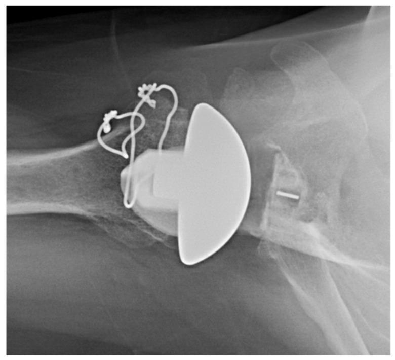
This axillary view X-ray of the shoulder demonstrates a total shoulder arthroplasty featuring an inlay glenoid polyethylene component, specifically indicated for glenoid dysplasia. The humeral head has been replaced with a hemispherical prosthetic component. Adjacent to the prosthetic humeral head, cerclage wires or surgical suture wires are visible, secured to the proximal humerus with small radiopaque anchors, likely to reinforce a tuberosity osteotomy or soft tissue repair. The glenoid side shows a polyethylene inlay component seated within the native glenoid fossa. A small, horizontal radiopaque marker pin is visible within the glenoid component to facilitate radiographic assessment of its position and orientation. The joint space between the humeral prosthetic head and the glenoid surface is clearly maintained. This imaging is characteristic of orthopedic surgery for complex glenoid anatomy, highlighting the specialized use of inlay components to manage bone deficiency or dysplasia in shoulder reconstruction.
Walch classification glenoid wear patterns shoulder osteoarthritis
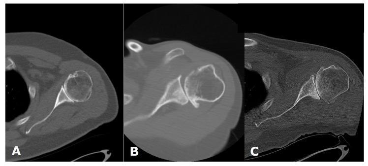
This image presents three axial computed tomography (CT) scans of the human shoulder, demonstrating the Walch classification system for glenoid morphology in primary glenohumeral osteoarthritis. Each panel illustrates a different stage of glenoid wear and humeral head alignment. Panel A shows a Walch A morphology, characterized by a centered humeral head and symmetric glenoid wear. Panel B demonstrates a Walch B1 morphology, where there is mild posterior joint space narrowing and subluxation of the humeral head without significant biconcavity. Panel C displays a Walch B2 morphology, highlighting significant posterior glenoid erosion and the development of a 'biconcave' glenoid surface, often resulting in severe posterior humeral head subluxation. Key anatomical landmarks visible include the humeral head, glenoid fossa, coracoid process, and scapular spine. These images serve as a diagnostic guide for preoperative planning in total shoulder arthroplasty, specifically for assessing glenoid version and bone stock loss.
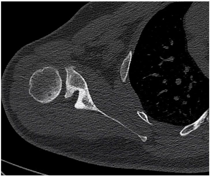
This diagnostic image is an axial CT scan of the right shoulder demonstrating advanced glenohumeral osteoarthritis. The primary finding is a Walch type B2 glenoid, characterized by a biconcave morphology of the glenoid fossa. The image shows a 'paleoglenoid' (the original, more anterior articular surface) and a 'neoglenoid' (the posterior, eroded surface created by chronic wear). This structural remodeling results in a significant posterior subluxation of the humeral head relative to the scapular axis. Key anatomical landmarks visible include the humeral head, the scapular body, and the lateral thoracic wall. The educational focus is on the assessment of glenoid bone loss and version abnormalities, which are critical for preoperative planning in total shoulder arthroplasty. The image serves as a clinical example of how eccentric loading in the shoulder joint leads to asymmetric posterior erosion and joint instability.
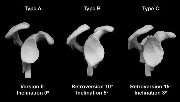
This comparative anatomical image displays three synthetic glenoid cast models representing Type A, Type B, and Type C morphologies according to the Walch classification of primary shoulder osteoarthritis. Each model is a 3D reconstruction based on clinical CT data, illustrating the progressive anatomical variations in version and inclination. - Type A: Shows a neutral morphology with 0° of version and 0° of inclination, representing a balanced glenoid surface. - Type B: Demonstrates 10° of retroversion and 5° of superior inclination, showing a visible posterior tilt and altered fossa orientation. - Type C: Exhibits 15° of retroversion and 3° of inclination, characterized by a more pronounced posterior tilt and significant dysplasia. The models include surrounding bony landmarks such as the scapular spine, acromion, and coracoid process, which serve as reference points for preoperative planning in total shoulder arthroplasty. This comparison is used in orthopedics to teach the visual assessment of glenoid bone loss and the necessary surgical correction angles required for implant positioning.
Total Shoulder Arthroplasty (TSA) - Comprehensive Review
1. OVERVIEW AND PRINCIPLES
- Restore humeral head size, offset, and version (normal humeral retroversion: ~20-30°)
- Correct glenoid version (normal: 3-10° retroversion)
- Preserve or restore the joint line height
- Ensure intact, functional rotator cuff for load sharing
- The subscapularis repair is fundamental - failure leads to anterior instability
- Anatomic TSA has superior outcomes compared with hemiarthroplasty in bipolar glenohumeral arthritis
- Glenoid resurfacing eliminates the pain source on the glenoid side and reduces stress on the humeral component
2. BIOMECHANICS
- Glenoid labrum (deepens glenoid cavity)
- Glenohumeral ligaments (inferior GHL is most important)
- Negative intra-articular pressure and joint congruity
- Rotator cuff muscles: compress the humeral head into the glenoid (concavity-compression mechanism)
- Deltoid: primary elevator; requires intact rotator cuff as fulcrum
| Parameter | Significance |
|---|---|
| Glenoid version | Excess retroversion leads to posterior subluxation and eccentric loading ("rocking horse" phenomenon) |
| Humeral head size | Undersized head causes instability; oversized causes stiffness and rotator cuff tension |
| Humeral offset | Restoring medial and posterior offset recreates deltoid tension and ROM |
| Glenoid fixation | All-polyethylene cemented glenoids are still gold standard; eccentric/asymmetric loading causes loosening |
| Center of rotation | Medialization of humeral head or lateralization of glenoid affects deltoid lever arm |
3. CLASSIFICATION OF GLENOID WEAR
A. Walch Classification (Primary OA)
| Type | Description |
|---|---|
| A1 | Concentric glenoid, no/minor central erosion, humeral head centered |
| A2 | Deep central erosion; line connecting anterior-posterior glenoid rims transects humeral head |
| B1 | Posterior joint space narrowing, no posterior bone loss; osteophytes, subchondral sclerosis |
| B2 | Biconcave glenoid - posterior rim erosion and retroversion; highest erosion at 7-8 o'clock (posteroinferior) |
| C | Glenoid retroversion >25°, regardless of erosion (dysplastic) |
B. Bercik et al. Modification of Walch (Most Widely Used Today)
| Type | Description |
|---|---|
| A1 | Same as Walch A1 |
| A2 | Line from anterior to posterior glenoid rims transects humeral head |
| B1 | Same as Walch B1 |
| B2 | Same as Walch B2 |
| B3 | Monoconcave, posterior wear, ≥15° retroversion OR ≥70% humeral head subluxation |
| C | Retroversion >25°, regardless of erosion |
| D | Any level of glenoid anteversion, or humeral head subluxation <40% (anterior subluxation) |
C. Sperling et al. (Severity-Based)
| Grade | Description |
|---|---|
| None | No bone loss |
| Mild | Erosion into subchondral bone |
| Moderate | Hemispheric deformation and medialization of subchondral bone |
| Severe | Bone loss extending to the coracoid base |
D. Antuna et al. (Revision/Periprosthetic)
- Central defects
- Peripheral defects
- Combined defects
4. INDICATIONS
- Primary glenohumeral osteoarthritis - most common; posterior glenoid wear (Friar Tuck wear pattern on humeral head), inferior osteophyte ("goat's beard"), posterior subluxation
- Rheumatoid arthritis - central glenoid wear, medialization, osteopenia, periarticular erosions
- Osteonecrosis (AVN) of the humeral head - stages III-IV with glenoid involvement
- Post-traumatic arthritis - after proximal humerus fractures, Hill-Sachs, etc.
- Capsulorrhaphy arthropathy - after overconstrained anterior stabilization
- Crystal arthropathy - CPPD, gout with end-stage joint destruction
- Post-septic arthritis (inactive, culture-negative)
- Failed hemiarthroplasty with significant glenoid erosion (painful glenoid erosion)
5. CONTRAINDICATIONS
- Active or recent joint infection
- Irreparable rotator cuff tear (relative - consider reverse TSA instead)
- Deltoid paralysis (complete loss of deltoid function)
- Debilitating medical status preventing safe surgery/anesthesia
- Uncorrectable glenohumeral instability
- Neuropathic (Charcot) arthropathy of the shoulder
- Young patients (<40 years): concern for implant longevity and need for revision
- Prior infection (needs careful evaluation; two-stage approach if serology elevated)
- Glenoid bone loss too severe for component fixation (B2/B3 severe erosion) - may need reverse TSA
- Significant noncompliance (inability to follow postoperative restrictions)
- Severe osteoporosis
- Diabetes mellitus: higher perioperative medical complications
- Hepatitis C: independent risk for infection and need for revision
- Underweight patients: at highest risk for early adverse events (higher than obese)
- Morbid obesity: impaired outcomes
- Perioperative mortality is ~1%; careful medical optimization required
6. PREOPERATIVE INVESTIGATIONS AND WORK-UP
Clinical Assessment
- History: pain localization, night pain, functional limitations, prior shoulder surgery, injections
- Physical examination: ROM (active vs. passive), rotator cuff strength testing, instability testing, neurovascular exam
- Assess deltoid function (axillary nerve integrity)
- Rule out cervical spine pathology (Spurling test, shoulder abduction relief sign)
Imaging
- True AP (Grashey view): humeral head positioning, joint space, osteophytes, bone loss
- Axillary lateral view: most important for glenoid version assessment, posterior subluxation, glenoid morphology
- Scapular Y view: acromion morphology
- Primary OA: posterior glenoid wear, "Friar Tuck" central humeral wear, "goat's beard" inferior osteophyte, posterior humeral subluxation
- Rheumatoid: central glenoid wear, medialization of humeral head, osteopenia, periarticular erosions, rare osteophytes
- CTA: proximal humeral head migration, decreased acromiohumeral distance, femoralization of proximal humerus, acetabularization of coracoacromial arch, superior glenoid wear
- Most important preoperative planning tool
- Assesses glenoid morphology and version (Walch classification)
- Quantifies remaining glenoid bone stock
- Determines need for glenoid augmentation or bone grafting
- Normal glenoid retroversion: 3-10°; normal humeral retroversion: 20-30°
- 3D reconstruction with planning software aids component placement
- Glenoid retroversion >17-18° often cannot be corrected with eccentric reaming alone
- Retroversion >20° typically does not allow standard glenoid component placement
- Assesses rotator cuff integrity (full-thickness tears in 5-10% of primary OA, 25-50% in RA)
- Evaluates fatty infiltration of rotator cuff muscles (Goutallier classification)
- Preoperative fatty infiltration of infraspinatus is a risk factor for postoperative cuff failure
- AVN staging (when osteonecrosis suspected)
- Evaluates labrum and capsule
- CBC, metabolic panel, coagulation studies
- If infection suspected: ESR, CRP, shoulder aspiration with culture and cell count
- If RA: medication review (DMARDs, biologics - coordinate with rheumatologist)
- Blood glucose (HbA1c if diabetic)
- Hepatitis C serology if risk factors
7. SURGICAL TECHNIQUES
Patient Positioning
Approach
- Incision from coracoid to deltoid insertion
- Interval between deltoid (axillary nerve) and pectoralis major (medial and lateral pectoral nerves)
- Cephalic vein mobilized laterally with the deltoid
- Subscapularis management is the key step - see below
- Subscapularis tenotomy - division at the lesser tuberosity insertion; most common; meticulous repair essential
- Lesser tuberosity osteotomy (LTO) - bone-to-bone healing potentially more reliable; used in revision cases
- Subscapularis peel - reflects tendon with a thin wafer of lesser tuberosity
- Humeral head osteotomy - cut based on anatomic neck; ~35-45° of retroversion preserved (matching contralateral side); ~45° inclination
- Humeral canal preparation with sequential reamers
- Broaching for press-fit (uncemented) or cemented stem
- Trial sizing: assess head size, offset, and stability
Glenoid Exposure and Preparation (TECHNIQUE 13.2 - Campbell's 2026):
- Posterior retractor translates humerus posteriorly
- Debride all labral tissue and articular cartilage
- Release anterior capsule; flat Darrach retractor on anterior glenoid neck
- Adequate exposure requires visualization of all four glenoid margins
- Inspect for wear pattern; typically posterior erosion (OA)
- Centering hole placement using guide pin (many systems are cannulated)
- Eccentric reaming to correct mild deformities (max 17-18° correctable); care not to violate subchondral bone
- For posterior erosion: ream anterior rim down to correct retroversion
- Prepare anchoring pegs or keel; ensure no rocking of trial
- Pulsed lavage and drying of peg holes before cementation
- Tuberculin syringes to pressurize cement into peg holes
- Insert glenoid component under sustained pressure until cement hardens
- Retroversion <17°: eccentric reaming usually sufficient
- Retroversion 17-20°: bone graft (autograft from humeral head, or allograft) to augment posterior rim
- Retroversion >20° or B3 glenoid: augmented glenoid component or reverse TSA
- Patient-specific instrumentation (PSI): guides based on preoperative CT improve component positioning accuracy
- Subscapularis repaired through drill holes or anchors - critical to healing
- Rotator interval may be closed
- Wound closure in layers
Stemless Shoulder Arthroplasty
- FDA approved; avoids medullary stem; metaphyseal fixation
- Preserves proximal humeral bone stock
- Benefits unproven in long-term follow-up compared to stemmed designs
- Current status: promising short-to-medium term results
8. CEMENTED vs. UNCEMENTED FIXATION
Humeral Component
| Cemented | Uncemented (Press-fit) | |
|---|---|---|
| Fixation | PMMA cement | Porous coating/hydroxyapatite for bone ingrowth |
| Primary stability | Immediate | Requires initial press-fit |
| Loosening rate | Low (~1.1% humeral loosening) | Comparable |
| Revision difficulty | More difficult (cement extraction) | Easier (modular, no cement) |
| Indications | Older patients, poor bone quality, revision | Younger, active patients; good bone quality |
| Current trend | Both widely used; uncemented gaining favor | Preferred in younger patients |
Glenoid Component
| Cemented All-Polyethylene | Metal-Backed (Uncemented) | |
|---|---|---|
| Design | UHMWPE; pegged or keeled | Metal baseplate + PE insert |
| Loosening rate | 5.3% (lower in modern implants) | Higher - not a viable long-term option |
| Failure mode | Radiolucent lines, cement debonding | PE wear, metal/PE dissociation, backside wear |
| Evidence | Long-term data available; preferred | Boileau et al. (JSES 2015): "not a viable long-term therapeutic option" |
| Advantages | Simple, proven, no backside wear | Potentially better bone ingrowth (theoretical) |
| Current recommendation | First-line choice | Abandoned by most surgeons for primary TSA |
- Pegged glenoid distributes load more uniformly
- Multiple studies support pegged over keeled design for lower loosening rates
- Complete component seating is mandatory; cement cannot compensate for malposition
9. POSTOPERATIVE CARE AND REHABILITATION
Phase I - Immediate Postoperative (Weeks 0-6)
- Arm in sling/immobilizer for 4-6 weeks
- Pendulum exercises begin day 1-2 (gravity-assisted passive motion)
- Passive ROM only - no active use of subscapularis (protect repair)
- Hand/wrist/elbow ROM exercises
- Elevation precautions: no active internal rotation against resistance
- Ice, analgesia
- Wound care
Phase II - Early Active Motion (Weeks 6-12)
- Active-assisted ROM progressing to active ROM
- Periscapular strengthening
- Avoid resisted internal rotation until subscapularis adequately healed (typically 12 weeks)
- Forward elevation and external rotation exercises
- Aquatic therapy may be initiated
Phase III - Strengthening (Months 3-6)
- Progressive rotator cuff strengthening
- Isotonic resistance exercises
- Functional activity training
- Avoid overhead lifting or impact loading
Phase IV - Return to Activity (Month 6 onward)
- Most patients return to light activity at 3-4 months
- Full recovery typically 6-12 months
- Activity restrictions long-term: avoid contact sports, heavy manual labor, and high-impact activities to protect the glenoid component from loosening
- Quality of rotator cuff directly influences functional result
- Compliance with subscapularis protection protocol
- Patient age, motivation, and overall health
- Pre-operative ROM (contracture affects recovery)
10. COMPLICATIONS
Complication Rates in Anatomic TSA
| Complication | % of All Shoulders | % of All Complications |
|---|---|---|
| Component loosening (total) | 6.3% | 39% |
| - Glenoid loosening | 5.3% | 32% |
| - Humeral loosening | 1.1% | 6.5% |
| Instability (total) | 4.9% | 30% |
| - Superior | 3% | 19% |
| - Posterior | 1% | 6% |
| - Anterior | 0.9% | 5% |
| Periprosthetic fracture | 1.8% | 11% |
| Rotator cuff tear | 1.3% | 7.7% |
| Neural injury | 0.8% | 4.8% |
| Infection | 0.7% | 4.6% |
| Deltoid detachment | 0.08% | 0.5% |
A. Glenoid Loosening (Most Common Complication - 32% of all complications)
- Progressive radiolucent lines at cement-bone interface
- Classified as asymptomatic (radiographic) vs. symptomatic
- Symptomatic loosening manifests as pain with activity and the "clunking sign"
- "Rocking horse" mechanism: superior cuff tear → eccentric superior glenoid rim loading → progressive loosening
- Management: revision glenoid replacement or conversion to reverse TSA
B. Glenohumeral Instability (Second Most Common - 30% of complications)
- ~80% involve anterior or superior instability
- Anterior instability: subscapularis failure, glenoid anteversion, humeral component malrotation, anterior deltoid dysfunction; using an undersized humeral head (Fig. 13.22)
- Superior instability: rotator cuff tear, component malpositioning
- Posterior instability: glenoid retroversion, humeral retroversion mismatch
- Treatment: identify cause; subscapularis repair (if repairable); revision if component malposition; often requires conversion to reverse TSA
C. Rotator Cuff Tear
- Postoperative rotator cuff failure is a persistent cause of anatomic TSA failure
- Risk factors: preoperative infraspinatus fatty infiltration, glenoid component in superior tilt
- Partial thickness tears do not significantly affect outcomes
- Large tears cause superior subluxation and eventual glenoid loosening
- Treatment: repair if possible; massive/irreparable tears require conversion to reverse TSA
D. Periprosthetic Fracture (Wright & Cofield Classification)
- Region 1: tuberosity
- Region 2: proximal metaphysis
- Region 3: proximal diaphysis
- Region 4: middiaphysis and distal diaphysis
- Avoid excessive ER during exposure
- Complete anterior and inferior capsular release
- Use bone hook to deliver humeral head from glenoid fossa
- Assistant holds arm loosely (to allow rotation with hand reamer)
E. Infection (~0.7-2%)
- Rare but indolent and difficult to diagnose
- Cutibacterium acnes (formerly Propionibacterium acnes) is the predominant organism for both anatomic and reverse TSA
- Risk factors: male sex, young age, diabetes, RA, SLE, systemic corticosteroids, biologic agents, injections within 3 months of surgery, remote infection sites
- Often presents late (months to years postoperatively) with subtle symptoms
- Diagnosis: elevated ESR/CRP, joint aspiration, prolonged culture (C. acnes requires 7-14 days growth)
- Treatment: two-stage revision arthroplasty (spacer then reimplantation)
F. Nerve Injury (~0.8%)
- Axillary nerve most commonly injured
- Brachial plexus injury possible
- Musculocutaneous nerve at risk during coracoid retraction
- Most are neurapraxia and recover with observation
G. Intraoperative Complications
- Two highest risk moments for humeral fracture: during reaming (assistant holds loosely), and during reduction/dislocation testing (use longitudinal distraction)
- Simple cerclage wiring usually adequate for intraoperative proximal fractures
H. Deltoid Weakness/Dysfunction
- Rare (0.08%) but devastating
- Due to axillary nerve injury
- Permanent deltoid loss is an absolute contraindication to shoulder replacement
11. RESULTS AND OUTCOMES
- 89% pain relief in OA; 91% in RA
- Average forward elevation improves from ~100° to ~140°
- External rotation typically improves significantly
- Anatomic TSA superior to hemiarthroplasty for bipolar disease
- 10-year survival rates: 85-95% for well-positioned cemented glenoid components
- Preoperative fatty infiltration of the rotator cuff
- Severe glenoid bone loss (B2/B3)
- Young age (<55 years) - higher revision rate
- Superior glenoid tilt (>10°)
- Non-compliance with rehabilitation
- Diabetes, hepatitis C, obesity
SUMMARY TABLE
| Topic | Key Points |
|---|---|
| Indication | End-stage GH arthritis + intact rotator cuff |
| Contraindication | Active infection, irreparable cuff tear, deltoid paralysis |
| Glenoid classification | Walch/Bercik (A1, A2, B1, B2, B3, C, D) |
| Approach | Deltopectoral; subscapularis management critical |
| Glenoid fixation | Cemented all-PE = gold standard |
| Humeral fixation | Both cemented and press-fit acceptable |
| Key complication | Glenoid loosening (5.3%); rocking horse mechanism |
| Top infective organism | Cutibacterium acnes |
| Failure requiring revision | Subscapularis failure → anterior instability → reverse TSA |
| Rehabilitation | Sling 4-6 weeks; active ROM from 6 weeks; strengthening from 3 months |
give me detailed information on arthroscopy in orthopaedics including principles, rational, instruments
arthroscopy orthopaedics principles instruments techniques portals setup 2024
arthroscope instrument set trocar cannula shaver knee arthroscopy equipment
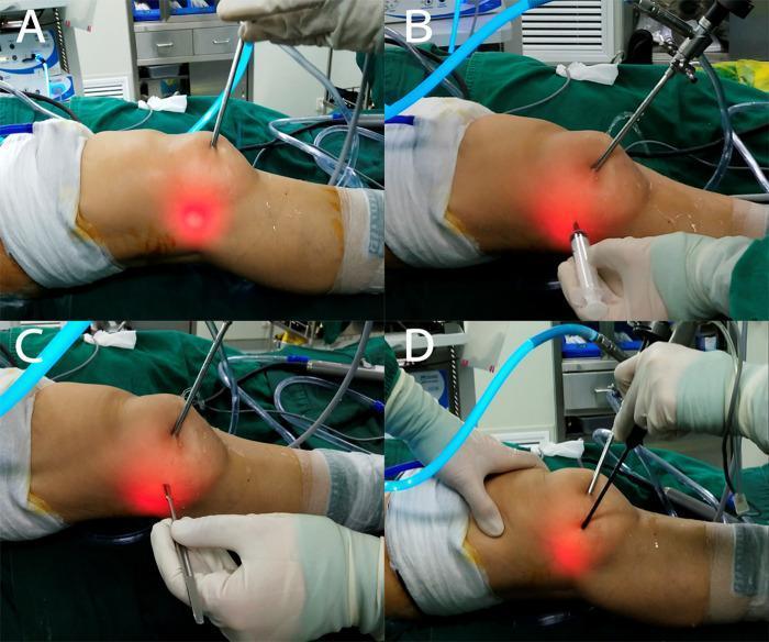
This set of four clinical photographs (A-D) demonstrates the intraoperative steps for establishing an auxiliary extreme lateral approach during knee arthroscopy. The patient's knee is prepped and draped in a standard sterile fashion. Image A shows the transillumination technique, where an arthroscope inside the joint creates a focal red light on the lateral aspect of the knee to guide portal placement. Image B illustrates the 'outside-in' technique using a spinal needle and syringe to confirm the entry point and trajectory into the joint space. Image C depicts the insertion of a switching stick or guide wire through the newly established portal, while an intra-articular instrument is positioned to receive it. Image D shows the final placement of an arthroscopic cannula or working instrument through the extreme lateral approach, with manual stabilization of the limb. This sequence highlights surgical techniques for improving access to lateral compartment structures, such as the lateral meniscus or popliteus tendon, during orthopedic procedures.
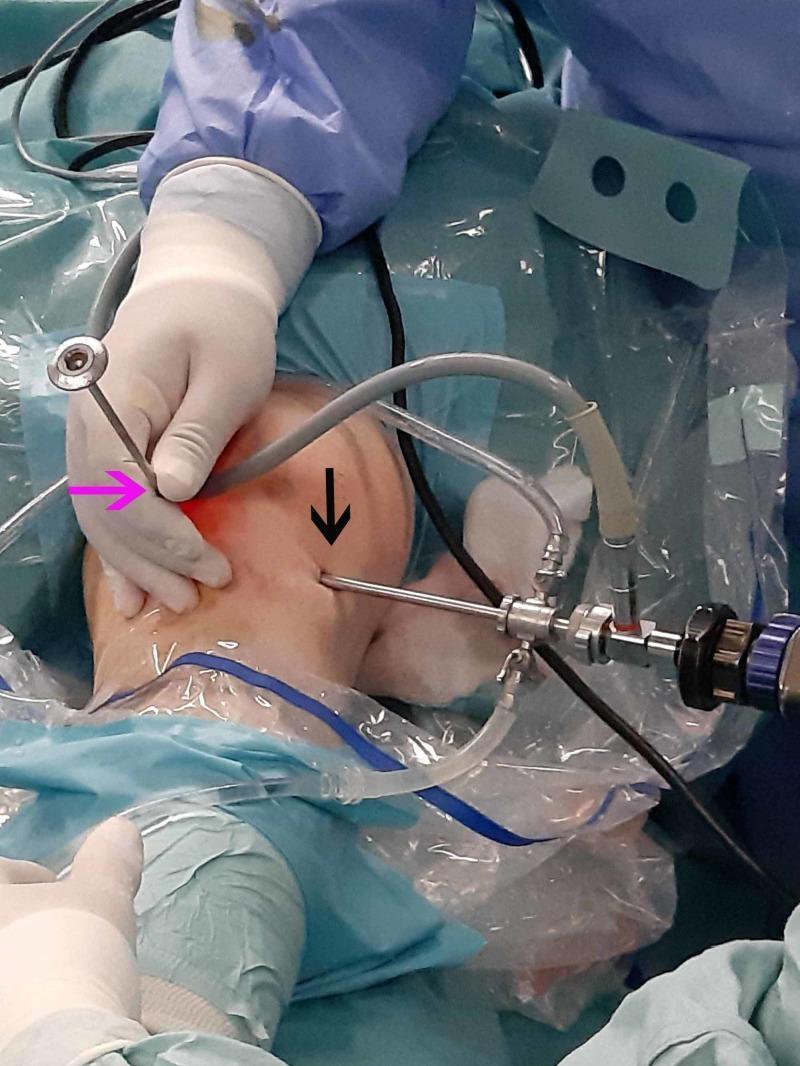
Clinical photograph of a knee arthroscopy procedure in an operating room environment. The image demonstrates standard surgical positioning, sterile draping with clear adhesive barriers, and instrumentation. Two primary surgical portals are identified: a pink arrow indicates the anteromedial portal where a blunt trocar is being manipulated by a gloved hand, and a black arrow indicates the anterolateral portal containing an arthroscope sheath equipped with light source cables and fluid irrigation tubing. The knee joint is distended, suggesting active fluid irrigation for visualization. The surrounding field is prepared with blue sterile drapes and the surgical team is wearing appropriate sterile attire. This image illustrates the external setup and portal placement necessary for intra-articular orthopedic interventions, specifically used here for the visualization and localization of an infrapatellar tumor.
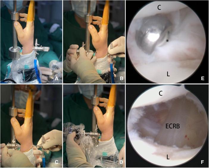
A multi-panel figure illustrating the 'Kiss-in' method for midcarpal arthroscopy (MCV) and subsequent ganglion cyst resection. Panels A through D are intraoperative clinical photographs showing a step-by-step surgical sequence. (A) Insertion of a blunt trocar into the radial midcarpal portal. (B) Meeting or 'kissing' of two trocar cannulas to form a continuous conduit. (C) Pushing the trocar assembly from the volar to the dorsal aspect through the joint. (D) Successful placement of the arthroscope through the established volar portal. Panels E and F provide intraarticular arthroscopic views during the procedure. (E) Visualization of the capitate (C) and lunate (L) bones with a surgical shaver (asterisk) excising the stalk of a ganglion cyst. (F) Continued debridement of the joint capsule distally toward the dorsal scapholunate ligament, exposing the underlying extensor carpi radialis brevis (ECRB) tendon. This visual material demonstrates an advanced technique for establishing portals and performing arthroscopic resection of wrist ganglia, highlighting key anatomical landmarks and instrument manipulation.
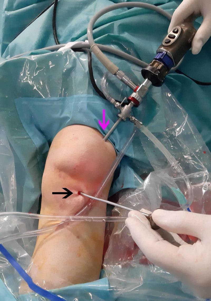
Clinical photograph of a left knee during an orthopedic arthroscopic procedure, highlighting surgical portal placement. The image displays two primary entry points: a superolateral portal (indicated by a pink arrow) and an anterolateral portal (indicated by a black arrow). An arthroscope with attached camera cables and irrigation tubing is inserted into the superolateral portal for intra-articular visualization. A metallic blunt trocar, held by a gloved hand, is inserted through the anterolateral portal for joint manipulation. The surgical field is prepared with sterile blue drapes and clear plastic adhesive drapes (incise drapes). The skin shows mild erythema localized around the puncture sites, consistent with acute surgical access. This image demonstrates the standard triangulation technique used in knee arthroscopy to evaluate intra-articular pathology, such as meniscus tears or localized masses, by utilizing one portal for visualization and another for instrumentation.
arthroscopy portals knee shoulder diagram anatomical landmarks
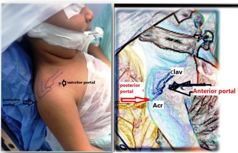
This clinical photograph and annotated anatomical diagram demonstrate preoperative surgical landmarks and portal planning for shoulder arthroscopy in a pediatric patient. The left image shows the patient in a supine beach chair position with surgical skin markings over the right shoulder. Key landmarks include the clavicle (clav) and the acromion (Acr), which are outlined to guide portal placement. The posterior portal is marked at the posterolateral corner of the acromion, providing the primary viewing entry point to the glenohumeral joint. The anterior portal is marked anteriorly, positioned to allow surgical access to the rotator interval, subscapularis tendon, and anterior capsule. The right image is a stylized, high-contrast overlay that emphasizes these osseous landmarks and the spatial relationship between the two portals, illustrating the triangulation technique required for arthroscopic visualization and instrumentation. This educational material is relevant for orthopedic surgical training, specifically for procedures involving glenohumeral joint contracture release or obstetric brachial plexus palsy sequelae.
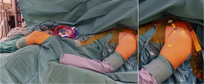
Clinical photograph showing a patient in the beach chair position prepared for left shoulder arthroscopy. The surgical site is draped with sterile blue covers and yellow antimicrobial incise drapes. A close-up view identifies key anatomical landmarks and planned surgical portal sites marked on the skin in yellow. The coracoid process (CP) is indicated by an arrow. The instrumentation portals are labeled as follows: the anterosuperior portal (AS) located superior to the coracoid; the anterior portal (A) positioned slightly inferior and medial; and the anterolateral portal (AL) located on the lateral aspect of the shoulder. The ipsilateral knee is also visible and draped, prepared for a semitendinosus (ST) graft harvest. This image demonstrates the standard preoperative setup and surface anatomy necessary for complex shoulder stabilization procedures, such as a subscapular sling technique for anterior shoulder instability.
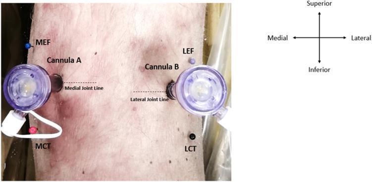
Clinical photograph and anatomical diagram showcasing the surgical portal placement in a posterior left knee cadaveric specimen. The image illustrates the positioning of two arthroscopic twist-in cannulas (labeled Cannula A and Cannula B) inserted into the direct posterior portals. Cannula A is situated along the medial joint line, while Cannula B is positioned along the lateral joint line. Key bony landmarks are identified with colored pins for surgical reference: the medial epicondyle of the femur (MEF), the medial condyle of the tibia (MCT), the lateral epicondyle of the femur (LEF), and the lateral condyle of the tibia (LCT). An orientation compass is included to define superior, inferior, medial, and lateral axes. This visual serves as an educational guide for orthopedic surgical training, specifically for establishing safe zones and avoiding neurovascular structures during posterior knee arthroscopy.
Arthroscopy in Orthopaedics - Comprehensive Review
1. HISTORY AND DEVELOPMENT
| Year | Milestone |
|---|---|
| 1912 | Severin Nordentoft (Denmark) - first described looking into joints |
| 1918 | Kenji Takagi (Tokyo University) - first true arthroscope (3.5 mm) for knee inspection |
| 1931 | Takagi published first arthroscopy results |
| 1932 | Michael Burman (USA) - cadaveric studies of multiple joints |
| 1957 | Masaki Watanabe (student of Takagi) - developed the No. 21 Watanabe arthroscope; published the Atlas of Arthroscopy |
| 1960s | Watanabe performed first meniscectomy (1962); Casscells and Jackson popularized in USA |
| 1970s-80s | Explosive growth; introduction of video cameras, motorized shavers |
| 1990s-present | Expansion to all joints; thermal devices, suture anchors, radiofrequency |
2. PRINCIPLES AND RATIONALE
Core Principles
- The arthroscope is placed in one portal (viewing portal) and the surgical instrument enters through a separate portal (working portal)
- The tip of the instrument and the tip of the arthroscope form the apex of a triangle - hence "triangulation"
- Separation of viewing from working instruments allows:
- Larger arthroscope = wider field of view
- Variable angle of inclination for access to more areas
- Independent movement of scope and instrument (essential for surgery)
- Improved depth perception
- Technique: Place scope at sufficient distance from the area (wide field), advance together toward target to increase magnification; if lost, slide instrument down arthroscope sheath to tip
3. ADVANTAGES vs. OPEN ARTHROTOMY
Advantages
- Reduced postoperative morbidity
- Immediate return to sedentary work; return to vigorous work 2-3 weeks after simple procedures
- Smaller incisions, less scarring
- Less intense inflammatory response, less postoperative pain, faster rehabilitation
- Improved visualization within the joint (magnification, illumination)
- Absence of secondary effects: no painful neuroma formation, no disfiguring scars, no potential functional imbalance (e.g., of knee extensor mechanism)
- Reduced hospital stay - mostly performed as outpatient
- Reduced overall complication rate
- Improved follow-up - "second-look" arthroscopy carries minimal morbidity
- Enables procedures impossible through arthrotomy (e.g., access to inaccessible meniscal regions, labral repair behind glenoid)
- Can be used to analyze and teach operative procedures (video documentation)
Disadvantages
- Can only be done by surgeons skilled in arthroscopic techniques
- Working through small portals limits available instruments
- Significant articular cartilage scuffing/scoring if inexperienced (in tight joints, long procedures)
- Time-consuming early in the surgeon's learning curve - steep learning curve
- Requires specialized equipment that may be expensive
- Patient expectations create pressure to attempt procedures beyond surgeon's skill level
- Key principle: A skillfully performed open arthrotomy is always preferable to a poorly performed arthroscopic procedure
4. INDICATIONS AND CONTRAINDICATIONS
Indications
- Persistent joint pain, swelling, or mechanical symptoms undiagnosed by non-invasive means
- Confirmation of pathology prior to treatment planning
- Biopsy of synovium or intra-articular tissue
- Second-look assessment of previous procedures (e.g., meniscal repair healing)
- Meniscal pathology (repair, partial meniscectomy)
- Anterior/posterior cruciate ligament reconstruction
- Rotator cuff repair, SLAP repair, Bankart repair
- Labral repair (shoulder, hip, ankle)
- Loose body removal
- Synovectomy (inflammatory arthritis, pigmented villonodular synovitis)
- Chondral procedures (microfracture, osteochondral grafting, ACI)
- Debridement (osteophyte removal, adhesion lysis)
- Fracture fixation assistance (tibial plateau, distal radius, scaphoid)
- Septic arthritis washout
- Capsular release for frozen shoulder
- Ganglion cyst excision
- FAI (femoroacetabular impingement) correction
Contraindications
- Active skin infection or cellulitis at proposed portal sites (risk of joint sepsis)
- Remote active infection that may seed the operative site
- Severe coagulopathy not correctable pre-operatively
- Minimally damaged joint that will respond to conservative management (arthroscopy should not be the first resort)
- Partial or complete ankylosis (relative - arthroscopy may be used for adhesion lysis)
- Major capsular and ligamentous disruption causing excessive fluid extravasation (allow 1-2 weeks for healing before arthroscopy; if done, use gravity inflow and maintain outflow)
- Surgeon inexperience with specific joint arthroscopy
5. INSTRUMENTS AND EQUIPMENT
A. The Arthroscope
| Component | Details |
|---|---|
| Outer diameter | 1.9 mm (small joints: wrist, ankle), 2.7 mm (standard small joints), 4.0 mm (standard knee/shoulder), 5.5 mm (hip) |
| Lens angle | 30° (most common) - provides offset viewing and allows panoramic view by rotating; 70° - used for hip, posterior knee, and specific shoulder views; 0° - straight forward view |
| Optics | Hopkins rod-lens system - glass rods separated by air; superior light transmission |
| Light transmission | Fiberoptic light cable connects to xenon or LED light source |
| Working length | Standard ~175 mm for knee; longer for hip |
| Sheath | Stainless steel outer sheath with inflow and outflow stopcocks; arthroscope slides inside |
B. Arthroscope Sheath and Trocars
| Instrument | Function |
|---|---|
| Sharp trocar | Initial penetration through capsule; used for primary portal entry in solid joints |
| Blunt trocar (obturator) | Inserted after capsule entry to advance scope without articular damage |
| Cannula/sheath | The outer sleeve through which scope and instruments pass; maintains portal patency; has inflow/outflow ports |
| Switching sticks | Smooth rods passed between portals to switch scope and instruments without losing portal position |
| Spinal needle | Used for portal localization ("outside-in" technique); confirms position before formal portal creation |
C. Light Source
- Xenon light source (300W): high-intensity, bright white light; connects via fiberoptic cable; standard
- LED light source: newer; cool, energy-efficient, long-lasting; increasingly preferred
- Fiberoptic light cable: flexible, connects scope to light source; handle carefully (breaks easily)
D. Camera and Video System
- Camera head: attaches to eyepiece of arthroscope; converts optical image to digital video signal
- Camera control unit (CCU): processes and displays video on monitor
- HD/4K monitors: minimum 1080p HD; 4K increasingly standard
- Recording system: captures still images and video for documentation, teaching, medico-legal purposes
- White balance: performed before each case by pointing scope at white gauze
E. Fluid Management System
| Component | Details |
|---|---|
| Irrigation fluid | Normal saline (0.9%) - most common; Lactated Ringer's also used; water causes osmotic red cell lysis (hemolysis) and must not be used |
| Fluid delivery | Gravity flow (bags elevated 1-2 m above patient) or arthroscopic pump |
| Arthroscopic pump | Electronically controlled; maintains set intra-articular pressure (typically 40-60 mmHg); provides continuous flow; reduces operating time |
| Inflow | Through arthroscope sheath or dedicated inflow cannula |
| Outflow | Through separate outflow cannula or passive via working portal |
| Epinephrine | Added at 1:300,000 concentration for hemostasis in shoulder arthroscopy |
- Monitor for excessive swelling
- Compartment syndrome possible (especially knee, hip, shoulder with large tears)
- Keep intra-articular pressure as low as possible while maintaining visualization
- Limit procedure time
F. Motorized Instruments (Power Instruments)
| Instrument | Use |
|---|---|
| Motorized shaver | Most versatile power instrument; oscillating/rotating blade with built-in suction; used for synovectomy, debridement, meniscal trimming, soft tissue work; blades come in various sizes (3.5-5.5 mm) and configurations (full-radius, aggressive, whisker) |
| Burr (abrader) | Round cutting burr; for bone work (microfracture prep, osteophyte removal, bony debridement) |
| Microdebrider | Fine cutting; for delicate work |
G. Hand Instruments (Manual Instruments)
| Instrument | Use |
|---|---|
| Probe (hook probe) | First instrument used in diagnostic arthroscopy; palpates structures (menisci, ligaments, articular cartilage) to assess integrity and probe tears; calibrated markings for size estimation |
| Grasper (forceps) | Grasps and removes loose bodies, meniscal fragments, sutures |
| Basket forceps (biters/punches) | Come in multiple angles (straight, 15°, 30°, 45°, 90° upbiting) and sizes; for meniscal trimming, tissue excision |
| Scissors | Straight and curved; for tissue division |
| Knives (blades) | Retrograde knife, banana knife; for capsulotomy, tissue release |
| Curette | For bone and soft tissue work |
| Rasps | Surface preparation |
H. Fixation and Repair Instruments
| Instrument | Use |
|---|---|
| Suture anchors | Threaded or knotless; for labral repairs (Bankart, SLAP), rotator cuff repair; loaded with high-strength suture |
| Suture passers/shuttles | Pass sutures through tissue; multiple designs (angled penetrators, bird-beak, piton) |
| Knot-tying instruments | Knot pusher, knot cutter; for arthroscopic knot tying |
| Bio-interference screws | For ACL/PCL graft fixation |
| Meniscal repair devices | All-inside devices (FasT-Fix, RapidLoc) and outside-in/inside-out needles |
I. Thermal Devices
| Device | Use |
|---|---|
| Radiofrequency (RF) ablation | Bipolar RF wand; tissue shrinkage/collagen tightening (capsulorrhaphy), hemostasis, tissue ablation; risk of osteonecrosis with prolonged use |
| Laser (Ho:YAG) | Holmium:YAG laser; tissue ablation; largely replaced by RF |
J. Accessory Equipment
| Equipment | Use |
|---|---|
| Tourniquet | Pneumatic; used in knee/ankle arthroscopy for hemostasis; inflate to 100 mmHg above systolic BP; limit to <2 hours |
| Leg holder | Holds lower leg in position during knee arthroscopy; allows valgus/varus stress |
| Post (lateral post) | Affixed to table for counter-pressure during valgus stress |
| Traction tower | For hip arthroscopy - provides longitudinal traction to distract joint |
| Shoulder distractor/traction | For shoulder arthroscopy in lateral decubitus position |
| C-arm fluoroscopy | Hip arthroscopy portal placement; confirmation of guide pin position |
6. ANESTHESIA FOR ARTHROSCOPY
General Anesthesia - Most Common
- Acute joint injury with significant pain
- Significant intra-articular surgery anticipated
- Uncooperative or apprehensive patient
- Allergy to local anesthetics
- Surgeon is less experienced or unfamiliar with technique
- Tourniquet anticipated for hemorrhage control
Regional Anesthesia
- Spinal/epidural: for lower extremity procedures (knee, ankle, hip)
- Interscalene nerve block: for shoulder arthroscopy; excellent analgesia; note - affects phrenic nerve (contraindicated in compromised pulmonary reserve); risk of postinjection neuritis in overhead athletes
- Saphenous/adductor canal block: for ACL surgery; purely sensory (no motor block); preferred over femoral nerve block (which causes quadriceps weakness)
- Femoral nerve block: avoided by many surgeons due to quadriceps weakness and fall risk
Local Anesthesia
- For knee and ankle in cooperative patients; with IV sedation
- Use lower concentrations: 1% lidocaine + 0.25% bupivacaine (chondrotoxicity risk)
- Add epinephrine to prolong action and maintain hemostasis for long procedures
- Do not inflate tourniquet when using local anesthesia
Postoperative Pain
- Ultrasound-guided regional blocks are safe and effective; used routinely
- NSAIDs, opioids, acetaminophen (multimodal)
- Avoid intra-articular pain pumps (prolonged chondrotoxic agent exposure)
7. PATIENT POSITIONING AND SETUP
Knee Arthroscopy
- Supine position - most common
- Leg holder (holds thigh; allows lower leg to hang) OR
- Post technique (lateral post at thigh for valgus/varus stress leverage)
- Tourniquet on proximal thigh
- Foot of table dropped; knee at 90° flexion for portal entry
Shoulder Arthroscopy
- Beach chair (semi-sitting) - 45-60° upright; head fixed; gravity assists dependent fluid drainage; anatomy familiar (upright); easier conversion to open; risk of air embolism, cerebral hypoperfusion
- Lateral decubitus - arm in 30-45° abduction with axial traction (5-10 lbs); better visualization of inferior glenoid; greater traction risk to brachial plexus
Hip Arthroscopy
- Supine or lateral decubitus on traction table
- Well-padded perineal post
- Fluoroscopic guidance for portal placement
- Traction applied until joint space opens adequately (8-10 mm)
Ankle/Small Joint Arthroscopy
- Supine with foot at end of table
- Distraction device (ankle) to open joint space (noninvasive soft strap or invasive pin distraction)
8. PORTALS
General Principles of Portal Placement
- Use a spinal needle first to confirm trajectory and position before making the skin incision
- Use a No. 11 blade for the skin incision only (stab incision)
- Use a blunt trocar to penetrate the capsule (prevents articular cartilage damage)
- Place portals away from neurovascular structures (know your anatomy)
- Mark all bony landmarks and neurovascular structures before starting
- Portals should provide optimal triangulation angles
Knee Arthroscopy Portals (Miller's Review, 9th Ed.)
| Portal | Location | Primary Use |
|---|---|---|
| Anterolateral (AL) | Lateral to patellar tendon, above joint line, with knee flexed | Viewing portal (arthroscope) |
| Anteromedial (AM) | Medial to patellar tendon, above joint line | Working portal (instruments) |
| Superomedial | 3-4 cm proximal to patella, medial | Inflow/outflow |
| Superolateral | 3-4 cm proximal to patella, lateral | Inflow/outflow (less needed with pump systems) |
| Posteromedial | 2.5 cm inferior and 2.5 cm posterior to medial epicondyle, knee in 90° flexion | Posterior horn meniscus, PCL |
| Posterolateral | 1 cm above joint line, between LCL and biceps tendon | Posterior compartment; avoid common peroneal nerve |
| Transpatellar | 1 cm distal to patella, splits patellar tendon longitudinally | Central viewing, Gillquist maneuver for posterior |
- Anteromedial: saphenous nerve and great saphenous vein (pass medially)
- Posteromedial: saphenous nerve, popliteal artery (avoid)
- Posterolateral: common peroneal nerve
- MCL can be torn by excessive valgus stress through a rigid leg holder
Shoulder Arthroscopy Portals (Miller's Review, 9th Ed.)
| Portal | Location | Primary Use |
|---|---|---|
| Posterior (standard) | 2 cm distal and medial to posterolateral acromial border | Primary viewing portal |
| Anterior | Just anterior to AC joint | Working portal; SLAP repair |
| Lateral | 1-2 cm distal to lateral acromial edge | Subacromial work; rotator cuff repair |
| Neviaser (Supraspinatus) | Through supraspinatus fossa, superior | Anterior glenoid visualization, SLAP repair |
| Anterolateral / Wilmington | Just anterior to posterolateral corner of acromion | SLAP tears, labral/cuff repair |
| Anteroinferior (5-o'clock) | Anteroinferior position | Bankart repair, anterior stabilization |
| Posteroinferior (7-o'clock) | Posteroinferior | Posterior stabilization |
- Posterior portal: axillary nerve (~12 mm distal to 6-o'clock position), suprascapular nerve, suprascapular artery
- Anterior portals: cephalic vein, axillary artery, axillary nerve
- Superior portals: suprascapular artery and nerve
- Axillary nerve: at 6-o'clock position, has already branched into 4 divisions - explains why most post-arthroscopy axillary neurapraxias are isolated sensory deficits (branch to teres minor injured)
Hip Arthroscopy Portals
| Portal | Location | Primary Use |
|---|---|---|
| Anterolateral (AL) | Just anterior to tip of greater trochanter | Primary viewing portal |
| Anterior (AP) | Intersection of vertical line from ASIS and horizontal line at tip of GT | Working portal |
| Proximal Mid-Anterior (PMAP) | Between AL and AP, more proximal | Labral work |
| Posterolateral | Just posterior to greater trochanter | Posterior compartment |
Elbow Arthroscopy Portals
- Anterolateral: anterior to lateral epicondyle - risk: posterior interosseous nerve (within 7-11mm)
- Anteromedial: anterior to medial epicondyle - risk: median nerve
- Posterolateral: posterolateral soft spot
- Posteromedial: risk: ulnar nerve (must protect)
- Note: Most elbow nerve palsies are transient (local anesthetic, tourniquet, blunt injury)
9. BASIC ARTHROSCOPIC TECHNIQUE
Step-by-Step Procedure
- Patient marking: Patient marks operative side; surgeon marks operative site; "Wrong Site" prevention protocol
- Positioning and draping: Joint accessible in full ROM
- Landmark marking: Draw bony landmarks and neurovascular structures with marker pen
- Tourniquet inflation (knee/ankle) or traction application (hip/shoulder)
- Primary portal entry:
- Skin incision (stab, No. 11 blade)
- Sharp trocar penetrates through skin and fascia
- Blunt obturator advances into joint
- Irrigation fluid fills joint (distension confirms position)
- White balance of camera
- Systematic diagnostic survey before any surgery
- Working portal: Use spinal needle to confirm before skin incision; blunt trocar entry
- Triangulation: Operative arthroscopy proceeds
- Completion: Remove scope, aspirate remaining fluid, portal closure (suture or steri-strip), dressing
Systematic Knee Diagnostic Survey (must include all areas)
- Suprapatellar pouch
- Patellofemoral joint and tracking
- Medial gutter
- Lateral gutter
- Medial compartment (medial meniscus, articular surface)
- Lateral compartment (lateral meniscus, articular surface)
- Intercondylar notch (ACL, PCL)
- Posterior compartment (via transpatellar/posteromedial portal - Gillquist maneuver)
Systematic Shoulder Diagnostic Survey
- Biceps tendon and origin
- Superior labrum (SLAP)
- Rotator interval (subscapularis, SGHL, MGHL)
- Articular surfaces (humeral head, glenoid)
- Inferior glenohumeral ligament (IGHL) - most important static stabilizer
- Posterior capsule/labrum
- Subacromial space (bursa, rotator cuff, coracoacromial ligament)
10. COMPLICATIONS OF ARTHROSCOPY
A. Intra-articular Structure Damage
- Articular cartilage scuffing/scoring by scope or instrument tip
- Most common in inexperienced surgeons, tight joints, long procedures
- Prevention: Open joint with leverage/traction first; allow scope to slide into created space; use leg holder/leverage post; use blunt trocars; never force scope between articular surfaces
B. Hemarthrosis
- Most common early complication
- Risk proportional to procedure complexity
- Management: ice, compression, aspiration if tense
C. Infection (Septic Arthritis)
- Rate: ~0.04-0.1%
- Risk factors: diabetes, immune suppression, steroid use, prolonged procedure
- Prevention: preoperative antibiotics (AAOS protocol), thorough skin prep, sterile technique
- Treatment: urgent arthroscopic washout + antibiotics
D. Nerve Injury
- Knee: Saphenous/sartorial branches of femoral nerve (most common); hypesthesia usually minor; occasional painful neuroma requiring excision
- Shoulder: Axillary nerve (portal too inferior); brachial plexus traction neurapraxia (30° forward elevation + 70° abduction = highest risk position)
- Elbow: Posterior interosseous nerve (anterolateral portal), median nerve (anteromedial), ulnar nerve (posteromedial) - usually transient
- Mechanism: Direct trauma from sharp trocar, excessive traction/distraction, mechanical compression from fluid, tourniquet ischemia
E. Thromboembolic Disease (DVT/PE)
- Rate: 0.12-0.17% in lower extremity arthroscopy
- Risk higher in complex procedures (ACL, meniscal repair)
- Chemoprophylaxis for higher-risk patients; early mobilization
F. Instrument Breakage
- Immediately close outflow cannula (reduce turbulence)
- Keep inflow open (maintain joint distension so fragment visible)
- Keep fragment in visual field at all costs
- Fragments gravitate to gutters, under menisci, or posteriorly (dependent part)
- Use suction/magnet through accessory portal, or grasper through third portal
- If fragment not found: radiograph to locate metallic fragment
G. Fluid-Related Complications
- Fluid extravasation into soft tissues
- Compartment syndrome (rare but devastating)
- Chondrolysis from local anesthetic intra-articular pumps
- Use lowest effective pressure; gravity inflow with outflow maintained in capsular injuries
H. Implant Complications
- Suture anchors/knots/sutures cause chondral damage, synovitis, osteolysis
- Evaluate with MRI; arthroscopic removal if symptomatic
I. Hernia of Synovium
- Herniated synovium through portal sites
- Most resolve spontaneously; symptomatic: excision + capsule closure
J. Synovial Fistula
- After suture reactions or stitch abscesses
- More common with posteromedial knee and ankle portals
- Prevention: routinely suture these portals (not steri-strips)
- Management: antibiotics, immobilization 7-10 days
K. Osteonecrosis
- Rare; reported after laser or RF-assisted arthroscopy (thermal damage to subchondral bone)
- Femoral condyle most common site in knee
L. Ligament and Tendon Injury
- MCL injury from excessive valgus stress with rigid leg holder
- Prevention: use spinal needle to "pie-crust" MCL under gentle controlled stress
11. ARTHROSCOPY BY JOINT - SUMMARY TABLE
| Joint | Scope Size | Key Portals | Unique Considerations |
|---|---|---|---|
| Knee | 4.0 mm, 30° | AL, AM, SM, SL | Most common; tourniquet; leg holder |
| Shoulder | 4.0 mm, 30° | Posterior, Anterior, Lateral | Beach chair or lateral decubitus; subacromial space |
| Hip | 4.5-5.5 mm, 70° | Anterolateral, Anterior | Traction table; fluoroscopy; longest learning curve |
| Ankle | 2.7-4.0 mm, 30° | Anterolateral, Anteromedial | Distraction device; small joint |
| Elbow | 2.7-4.0 mm, 30° | Anterolateral, Anteromedial, Posterolateral | High neurovascular risk; must inflate before entry |
| Wrist | 1.9-2.7 mm, 30° | 3-4 portal, 4-5 portal | Smallest joint; traction tower; fluoroscopy |
| Subtalar | 2.7 mm, 30° | Posterolateral, Posteromedial | Traction required; limited space |
12. APPLICATIONS OF ARTHROSCOPY IN ORTHOPAEDICS
Knee
- Meniscal tear: partial meniscectomy, repair (inside-out, outside-in, all-inside)
- ACL/PCL reconstruction
- Chondral procedures: microfracture, OATS, ACI
- Loose body removal
- Synovectomy (RA, PVNS, crystal arthropathy)
- Patellofemoral: lateral release, MPFL reconstruction
- Posterior cruciate ligament reconstruction
- Multi-ligament injuries
Shoulder
- Rotator cuff repair (partial/full-thickness tears)
- SLAP repair / biceps tenodesis
- Bankart repair (anterior instability)
- Posterior capsular labral repair
- Acromioplasty / subacromial decompression
- AC joint resection (Mumford procedure)
- Capsular release (frozen shoulder)
- Superior capsule reconstruction
Hip
- Labral repair/debridement
- FAI correction (cam/pincer resection)
- Ligamentum teres debridement
- Loose body removal
- Synovectomy
- Iliopsoas tendon release
Ankle/Foot
- Anterior ankle impingement (osteophytes)
- OCD (osteochondral defect of talus) - microfracture, OATS
- Ankle instability (arthroscopic Broström)
- Posterior impingement (os trigonum excision)
- Subtalar arthrodesis
Elbow
- Loose body removal
- Medial instability assessment
- Posteromedial osteophyte removal
- Lateral epicondyle release
- Osteochondritis dissecans of capitellum
Wrist
- TFCC repair/debridement
- Scaphoid fracture fixation
- Ganglion cyst excision
- Carpal instability assessment
- Ligament repair (SL, LT)
13. RECOMMENDED PRACTICES (Campbell's 2026)
- Thorough hair removal with clippers (not razors) before arthroscopy - infection prevention
- Antibiotics per AAOS Advisory Statement for Total Joints
- Sterile technique throughout
- General anesthesia for most procedures
- Do not inflate tourniquet if local anesthesia used
- Caution with interscalene blocks in respiratory-compromised patients
- Saphenous/adductor canal blocks preferred over femoral blocks (motor-sparing)
- If procedure not progressing as expected arthroscopically: abort and convert to open - a skillful open procedure is always preferable to a poor arthroscopic one
- Attend workshops, courses, observe skilled arthroscopists - ongoing education essential
- Steep learning curve for hip arthroscopy: seek formal training
abductor mechanism of shoulder
shoulder abduction mechanism deltoid rotator cuff force couple scapulohumeral rhythm diagram
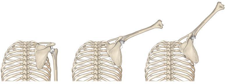
This medical illustration presents a comparative sequence of three panels demonstrating modified scapulohumeral rhythm in a patient with a reverse total shoulder arthroplasty (rTSA). The diagram shows the rib cage, scapula, and humerus during progressive arm elevation: at rest, at approximately 45 degrees, and at 90 degrees of abduction. Visible prosthetic components include a convex glenosphere mounted on the scapula and a corresponding concave humeral liner. A dashed line overlay indicates the native scapular position for comparison. The illustration highlights the biomechanical shift where, in rTSA, the scapula undergoes greater upward rotation relative to the humerus to compensate for altered joint mechanics and rotator cuff insufficiency. This increased scapular contribution is shown as a compensatory mechanism to achieve functional range of motion, providing a visual explanation of how prosthetic design influences dynamic musculoskeletal kinematics in orthopedic rehabilitation.
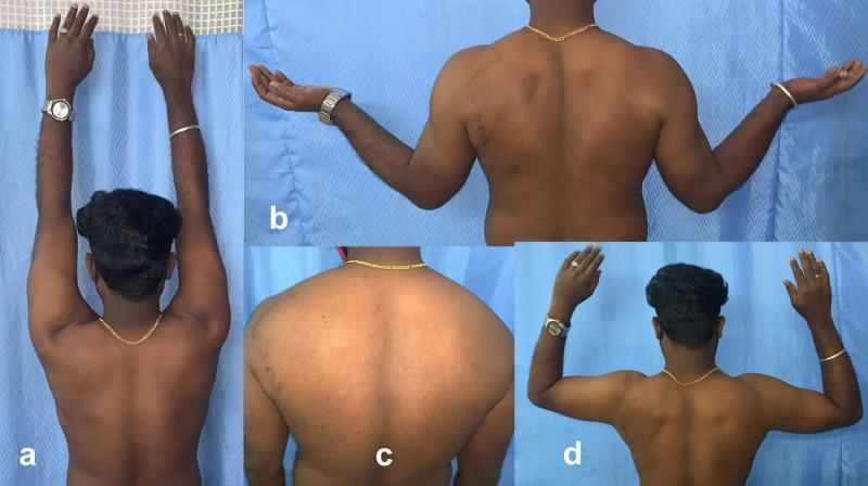
This composite of four clinical photographs (a-d) displays a posterior view of a patient’s upper back and shoulders during a postoperative orthopedic follow-up. The images assess the functional recovery of the shoulder following decompression of the suprascapular nerve. Panel (a) demonstrates full active overhead abduction (approximately 180 degrees), showing symmetrical scapulohumeral rhythm. Panel (b) shows the patient with shoulders abducted to 90 degrees and in external rotation with elbows extended, highlighting a surgical scar on the left posterior shoulder. Panel (c) provides a neutral-position close-up of the back, demonstrating the restoration of muscle mass in the infraspinatus and supraspinatus fossae, indicating the resolution of previous neurogenic muscle wasting. Panel (d) shows active external rotation with the shoulders and elbows flexed at 90 degrees. The collection illustrates a successful clinical outcome following the treatment of suprascapular nerve entrapment at the spinoglenoid notch, emphasizing the return of muscle bulk, symmetry, and full range of motion in the rotator cuff and deltoid groups.
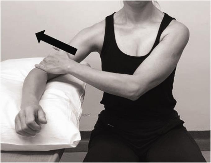
This clinical photograph demonstrates an isometric strengthening exercise for the middle deltoid, typically utilized in postoperative rehabilitation following Reverse Total Shoulder Arthroplasty (RTSA) or for patients with rotator cuff deficiency. The patient is shown in a seated position, wearing a sleeveless top to allow for visualization of shoulder mechanics. The target arm is positioned in approximately 30 to 45 degrees of abduction in the scapular plane, with the elbow resting on a supportive cushion. A black directional arrow indicates an upward force, representing isometric abduction where the patient resists gravity or provides self-resistance. This specific positioning is designed to optimize recruitment of the middle deltoid fibers while maintaining joint stability and minimizing stress on the acromion. The exercise is fundamental in physical therapy protocols aimed at improving deltoid activation and compensatory stabilization in the absence of a functional rotator cuff.
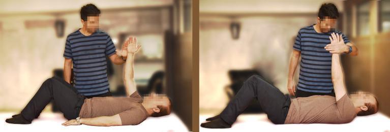
This clinical photograph consists of two panels demonstrating a therapeutic shoulder exercise, specifically manual resistance during shoulder abduction. The patient is positioned supine on a flat surface with knees flexed and feet flat. In the left panel, the patient has one arm raised vertically (flexed to 90 degrees at the shoulder) while an assistant stands beside him, preparing to apply medial force. In the right panel, the assistant provides manual resistance toward the patient’s midline (adduction force), which the patient counteracts by pushing outward against the assistant’s hand (abduction). This procedure represents a neuromuscular re-education or strengthening exercise for the rotator cuff and deltoid muscles. The setting is a rehabilitation or clinical environment. Educational focus is on manual resistive training (MRT) techniques used in physical therapy for upper extremity stabilization and strength progression.
shoulder abduction arc supraspinatus deltoid scapulohumeral rhythm 180 degrees elevation anatomy
This composite of four clinical photographs (a-d) displays a posterior view of a patient’s upper back and shoulders during a postoperative orthopedic follow-up. The images assess the functional recovery of the shoulder following decompression of the suprascapular nerve. Panel (a) demonstrates full active overhead abduction (approximately 180 degrees), showing symmetrical scapulohumeral rhythm. Panel (b) shows the patient with shoulders abducted to 90 degrees and in external rotation with elbows extended, highlighting a surgical scar on the left posterior shoulder. Panel (c) provides a neutral-position close-up of the back, demonstrating the restoration of muscle mass in the infraspinatus and supraspinatus fossae, indicating the resolution of previous neurogenic muscle wasting. Panel (d) shows active external rotation with the shoulders and elbows flexed at 90 degrees. The collection illustrates a successful clinical outcome following the treatment of suprascapular nerve entrapment at the spinoglenoid notch, emphasizing the return of muscle bulk, symmetry, and full range of motion in the rotator cuff and deltoid groups.
This medical illustration presents a comparative sequence of three panels demonstrating modified scapulohumeral rhythm in a patient with a reverse total shoulder arthroplasty (rTSA). The diagram shows the rib cage, scapula, and humerus during progressive arm elevation: at rest, at approximately 45 degrees, and at 90 degrees of abduction. Visible prosthetic components include a convex glenosphere mounted on the scapula and a corresponding concave humeral liner. A dashed line overlay indicates the native scapular position for comparison. The illustration highlights the biomechanical shift where, in rTSA, the scapula undergoes greater upward rotation relative to the humerus to compensate for altered joint mechanics and rotator cuff insufficiency. This increased scapular contribution is shown as a compensatory mechanism to achieve functional range of motion, providing a visual explanation of how prosthetic design influences dynamic musculoskeletal kinematics in orthopedic rehabilitation.
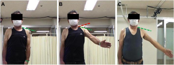
This clinical photograph sequence illustrates compensatory movement patterns in a patient with deltoid muscle weakness during shoulder rehabilitation. The images demonstrate the 'shrugging motion' used to achieve arm elevation. (A) Baseline/Resting state: The green dashed line indicates the neutral anatomical position of the acromion and scapula with the arm at the side. (B) Compensatory motion: During early rehabilitation, the patient attempts arm abduction, resulting in excessive superior migration of the scapula and acromion (indicated by the red dashed line) above the baseline. This 'shrug' signifies over-reliance on the upper trapezius to compensate for deficient deltoid strength. (C) Improved motor control: Following intervention, the patient achieves similar arm elevation while maintaining the acromion at the baseline level (green dashed line), indicating successful isolation of the glenohumeral joint and reduction of compensatory shrugging. The images are used to teach clinical assessment of scapulohumeral rhythm and the evaluation of rehabilitation progress in neuromuscular shoulder dysfunction.
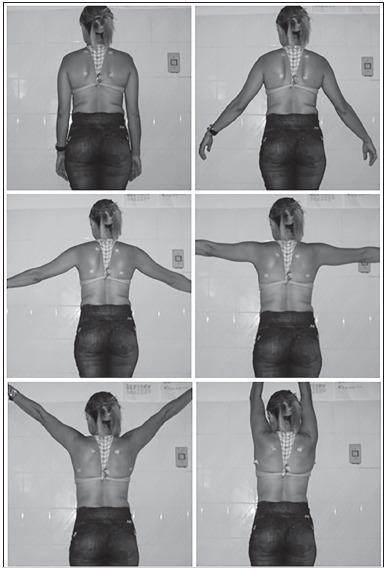
A series of six clinical photographs in black and white, capturing a posterior view of a human subject to demonstrate scapular kinematics during shoulder abduction. The sequence displays progressive bilateral arm abduction in the frontal plane at standardized intervals: 0 degrees (pendant position), 30 degrees, 60 degrees, 90 degrees, 120 degrees, and maximum abduction (approximately 170-180 degrees). Anatomical surface markers are visible on the subject's back, specifically positioned at the superior and inferior angles of the scapulae to facilitate biophotogrammetry analysis. The images illustrate the scapulohumeral rhythm, showing the upward and lateral rotation of the scapula as the humerus is elevated. This clinical imaging series is typical for orthopedic or physical therapy assessments of scapular dyskinesis, shoulder range of motion, and biomechanical studies of the shoulder complex.
rotator cuff force couple deltoid depressor humeral head superior migration diagram
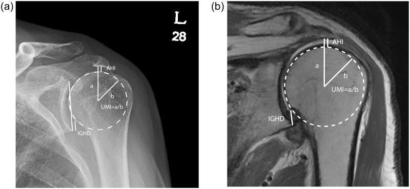
This figure presents a comparative analysis of shoulder joint measurement techniques using two different imaging modalities: (a) an anterior-posterior (AP) radiograph and (b) a coronal T1-weighted magnetic resonance image (MRI). Both images illustrate the quantitative assessment of superior humeral head migration, a key clinical indicator of rotator cuff pathology. The diagrams demonstrate three primary radiographic indices: the Acromiohumeral Interval (AHI), measured as the vertical distance between the inferior surface of the acromion and the superior margin of the humeral head; the Inferior Glenohumeral Distance (IGHD), defined between the inferior glenoid tubercle and the inferior humeral head margin; and the Upward Migration Index (UMI). The UMI is visually calculated by dividing the distance 'a' (lowest acromion point to the center of the humeral head) by 'b' (the radius of the humeral head). The radiograph (a) emphasizes high-density cortical bone structures, while the MRI (b) provides superior soft tissue resolution, allowing for better visualization of the deltoid muscle, subacromial space, and glenohumeral articular surfaces. This comparison highlights the multi-modal approach used in orthopedic radiology to evaluate shoulder stability and cuff integrity.
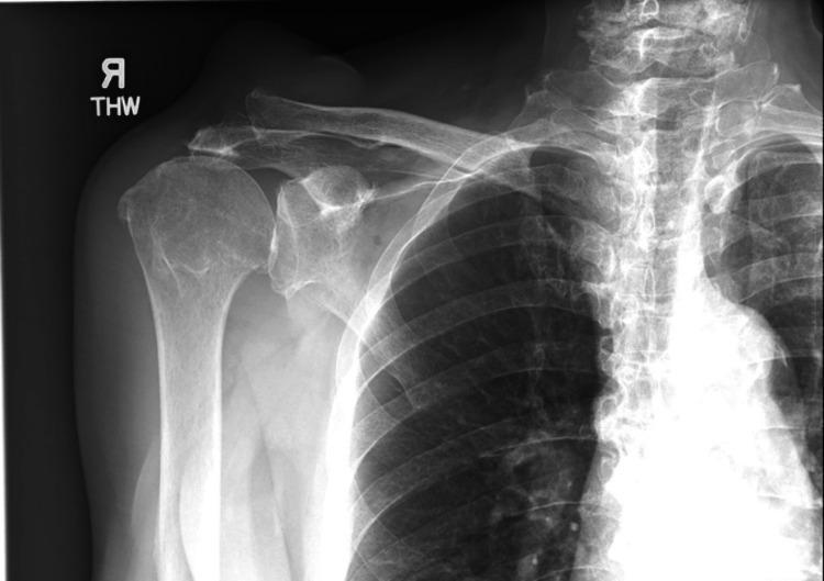
Anteroposterior (AP) radiograph of the right shoulder demonstrating classic hallmarks of rotator cuff arthropathy. The primary finding is a 'high-riding' humerus, characterized by the superior migration of the humeral head relative to the glenoid fossa. This leads to a marked reduction in the acromiohumeral distance, with the humeral head positioned closely beneath the inferior surface of the acromion. Adjacent to the acromioclavicular joint (ACJ), there is a prominent, well-defined soft tissue density suggesting significant swelling or a cystic mass. The bony structures show degenerative changes, including subchondral sclerosis and potential osteophyte formation. These visual features are pathognomonic for a chronic, massive rotator cuff tear where the loss of the inferior force couple allows the deltoid to pull the humerus superiorly. The associated ACJ soft tissue mass in this clinical context likely represents a Geyser sign, indicating a synovial cyst communicating with the glenohumeral joint due to chronic cuff deficiency.
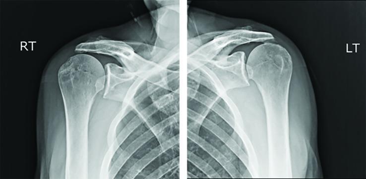
This diagnostic image consists of two anteroposterior (AP) radiographs of the right (RT) and left (LT) shoulders. The primary finding is bilateral superior migration of the humeral heads relative to the glenoid fossae, commonly referred to as high-riding humeral heads. This positioning significantly reduces the subacromial space, indicating a high likelihood of massive rotator cuff tears where the stabilizing downward force of the cuff is lost, allowing the deltoid to pull the humerus superiorly. Despite the superior translation, the glenohumeral joints remain concentrically reduced, with articular surface contact maintained. The bony structures, including the clavicles, scapulae (acromion and coracoid processes), and proximal humeri, appear intact without evidence of acute fractures or dislocations. There is visible cystic change or remodeling on the greater tuberosity of the right humerus, often associated with chronic tendinopathy or previous avulsion. This visual is characteristic of rotator cuff arthropathy and is a critical teaching tool for identifying indirect signs of soft tissue injury on plain film radiography.
Abductor Mechanism of the Shoulder
1. JOINTS INVOLVED IN SHOULDER ABDUCTION
| Joint | Contribution |
|---|---|
| Glenohumeral joint | 120° (2/3 of total motion) |
| Scapulothoracic joint | 60° upward scapular rotation (1/3 of total motion) |
| Sternoclavicular joint | Clavicular elevation (~35°) and rotation (~50°) |
| Acromioclavicular joint | Fine adjustment of scapular tilt (~20°) |
2. SCAPULOHUMERAL RHYTHM
The Classic 2:1 Ratio
- For every 3° of total shoulder abduction, the glenohumeral joint contributes 2° and the scapula rotates upward 1°
- This 2:1 (GH:scapulothoracic) ratio maintains the glenoid fossa oriented upward under the humeral head throughout the arc of motion
Phases of Abduction
| Phase | Arc | What happens |
|---|---|---|
| Setting phase | 0-30° (some say 0-60°) | Variable ratio; humerus moves on a relatively fixed scapula while scapula "seeks" its best position; muscles "set" the rhythm |
| Active phase | 30-170° | Consistent 2:1 ratio; simultaneous glenohumeral and scapulothoracic motion |
| Terminal phase | Near full elevation | External rotation of humerus mandatory to clear greater tuberosity under acromion |
Why Scapular Rotation is Essential
- The glenoid points downward, destabilizing the joint
- The acromion descends and impinges on the rotator cuff and greater tuberosity
- The origins of deltoid and rotator cuff shorten, reducing their mechanical advantage
- Full elevation is impossible (~90° maximum without scapular rotation)
3. MUSCLES OF SHOULDER ABDUCTION
PRIMARY ABDUCTORS
A. Supraspinatus
- Origin: Supraspinous fossa of scapula
- Insertion: Superior facet of greater tuberosity of humerus
- Nerve: Suprascapular nerve (C5, C6)
- Role: Initiates abduction; active throughout the entire arc; contributes ~50% of abduction force
- Moment arm: Pulls the humeral head laterally and upward into the glenoid (compression + abduction)
- Classic teaching: "Initiates the first 15°" - though EMG studies show it is active throughout the full arc, not just the first 15°
- Key function: Works in concert with the deltoid as a force couple - the rotator cuff (infraspinatus, subscapularis, teres minor + supraspinatus) depresses the humeral head while the deltoid elevates it
B. Middle Deltoid
- Origin: Lateral border of acromion
- Insertion: Deltoid tuberosity of humerus
- Nerve: Axillary nerve (C5, C6)
- Role: Primary mover of shoulder abduction from 15° onward; generates the largest abduction force moment
- Problem: Acts at an angle that tends to pull the humeral head superiorly against the acromion - this is why the rotator cuff is essential as a counter-force
SECONDARY ABDUCTORS
- Anterior deltoid: Abduction in the scapular plane; also flexion
- Posterior deltoid: Abduction in extension; acts during horizontal abduction
- Supraspinatus: See above - works throughout full arc
4. THE FORCE COUPLE CONCEPT (Most Important Biomechanical Principle)
The Glenohumeral Force Couple
| Force | Muscle | Direction |
|---|---|---|
| Elevating force (upward) | Deltoid | Pulls humerus superiorly |
| Depressing force (downward) | Rotator cuff (infraspinatus + subscapularis + teres minor + supraspinatus) | Compresses and depresses humeral head into glenoid |
- Together these two opposing forces produce pure rotation of the humeral head within the glenoid
- The rotator cuff acts as a dynamic depressor to counteract the superior vector of deltoid pull
- The glenohumeral joint contact point (center of rotation) is maintained on the glenoid face
- Normal acromiohumeral interval: 7-14 mm (average ~10 mm)
- The deltoid's unopposed superior pull migrates the humeral head superiorly
- Acromiohumeral interval narrows (<6 mm = significant)
- Impingement of greater tuberosity against the acromion
- "Shrugging" pattern (upper trapezius compensates)
- Eventual cuff tear arthropathy: "femoralization" of humeral head, "acetabularization" of coracoacromial arch
The Scapulothoracic Force Couple
| Force | Muscle | Direction |
|---|---|---|
| Upper force | Upper trapezius | Pulls lateral end of clavicle/scapula UP |
| Lower force | Lower trapezius + Serratus anterior | Pulls inferior angle of scapula UP and LATERAL |
- Upper trapezius acts on the clavicle (and via AC joint on the scapula) pulling it superiorly
- Serratus anterior (key muscle) protracts and rotates the inferior angle upward and laterally
- Lower trapezius pulls the scapular spine medially and downward, rotating the glenoid upward
- Together they create a rotating couple causing upward scapular rotation
- Serratus anterior weakness → medial winging + loss of upward rotation → maximum abduction ~90°
5. MUSCLE CONTRIBUTIONS BY ARC OF ABDUCTION
0-30°: Initiation ("Setting Phase")
- Supraspinatus: primary mover (pulls humeral head into glenoid + initiates abduction)
- Middle deltoid: low mechanical advantage at this range (insufficient moment arm)
- Scapula relatively fixed; slight upward rotation
30-90°: Active Elevation
- Deltoid dominates (optimal mechanical advantage at ~90°)
- Supraspinatus contributes throughout
- Rotator cuff depression increases proportionally with deltoid force
- Scapulohumeral rhythm 2:1 established
- At 90°: external rotation of humerus required to clear greater tuberosity under acromion; without ER, the greater tuberosity impinges on the acromion at ~60-90°
90-120°: Mid-arc
- Both deltoid and supraspinatus remain active
- Scapular rotation accelerates
- Thoracic extension facilitates further elevation
- Posterior deltoid contributes
120-180°: Overhead Elevation
- Scapulothoracic motion predominates (contributing remaining 60°)
- Upper and lower trapezius + serratus anterior are essential
- Glenohumeral contribution limited by soft-tissue constraints
- Sternoclavicular and acromioclavicular joints contribute final degrees
- Full elevation requires ipsilateral lateral trunk bending or contralateral trunk lean
6. ROLE OF INDIVIDUAL ROTATOR CUFF MUSCLES IN ABDUCTION
| Muscle | Origin | Insertion | Nerve | Role in Abduction |
|---|---|---|---|---|
| Supraspinatus | Supraspinous fossa | Superior facet, greater tuberosity | Suprascapular (C5,6) | Primary abductor; compresses head into glenoid; depresses superior |
| Infraspinatus | Infraspinous fossa | Middle facet, greater tuberosity | Suprascapular (C5,6) | External rotates (clears GT under acromion); posterior depressor |
| Teres minor | Lateral border of scapula | Inferior facet, greater tuberosity | Axillary (C5,6) | External rotates; inferior depressor |
| Subscapularis | Subscapular fossa | Lesser tuberosity | Upper/lower subscapular (C5,6) | Anterior stabilizer; anteroinferior depressor; completes the cuff ring |
7. THE CONCAVITY-COMPRESSION MECHANISM
- The glenoid labrum deepens the glenoid cavity
- The rotator cuff compresses the humeral head into the concave glenoid
- Increased compression force → increased stability (proportional relationship)
- This is why total rotator cuff loss is catastrophic - not just for force couple, but for passive stability too
8. EXTERNAL ROTATION DURING ABDUCTION
- As the humerus elevates past 60-90°, the greater tuberosity would impinge on the acromion
- External rotation of the humerus (infraspinatus + teres minor) rotates the greater tuberosity posteriorly away from the acromion
- This clears the subacromial space and allows continued elevation
- In frozen shoulder, loss of ER limits abduction to ~90°
- In supraspinatus tears with poor ER: impingement at 60-90° arc (painful arc)
9. WHAT HAPPENS WITHOUT KEY MUSCLES
Loss of Deltoid (Axillary Nerve Palsy)
- Abduction severely limited (cannot reach 90°)
- Supraspinatus can initiate weak abduction but without the major elevator, functional abduction is lost
- Deltoid paralysis = absolute contraindication to shoulder replacement
Loss of Supraspinatus
- Abduction weakened but not absent
- Deltoid can still abduct past 15° (the old "dead zone" concept is partially incorrect)
- However, unopposed deltoid causes superior head migration → painful arc → impingement
- Abduction strength reduced ~50% in isolated complete supraspinatus tears
Loss of Entire Rotator Cuff (Cuff Tear Arthropathy)
- No inferior depressor force couple
- Deltoid pulls humeral head superiorly
- Head migrates proximally → contacts acromion (femoralization/acetabularization)
- Pseudoparalysis possible: inability to actively abduct despite passive range preserved
- Maximum active abduction ~60-70°
- This is the key indication for reverse total shoulder arthroplasty - the medialized glenosphere compensates by lengthening the deltoid and using it as the sole abductor
Loss of Serratus Anterior (Long Thoracic Nerve Palsy)
- Medial winging of scapula (inferior angle moves posteriorly and medially)
- Loss of upward scapular rotation
- Maximum active abduction limited to ~90° (GH component only)
- Fatigues rapidly, painful arc
Loss of Trapezius (Spinal Accessory Nerve Palsy)
- Lateral winging of scapula (inferior angle moves medially)
- Loss of scapular upward rotation
- Drooping of shoulder girdle
- Significant functional impairment with abduction >90°
10. CLINICAL CORRELATIONS
| Clinical Finding | Underlying Mechanism |
|---|---|
| Painful arc (60-120°) | Greater tuberosity impinges on acromion/coracoacromial ligament during this arc - typically supraspinatus/subacromial pathology |
| Drop arm test positive | Inability to lower abducted arm slowly = complete supraspinatus tear (no eccentric control) |
| Shrug sign | Arm elevation by scapular hiking (upper trapezius) compensating for weak deltoid or massive cuff tear |
| Pseudoparalysis | Active abduction impossible despite full passive ROM = massive rotator cuff tear |
| Winging scapula | Serratus anterior palsy (medial winging) or trapezius palsy (lateral winging) |
| High-riding humerus on X-ray | Acromiohumeral distance <6 mm = massive rotator cuff tear with superior migration |
| Dead arm with abduction | Anterior instability - apprehension with abduction + ER |
11. SUMMARY: THE COMPLETE ABDUCTOR MECHANISM
0-30°    : Supraspinatus (initiates) + Middle deltoid (begins)
           Force couple established: Deltoid (up) ↕ Rotator cuff (down)

30-90°   : Deltoid dominates | Supraspinatus continues
           2:1 Scapulohumeral rhythm active
           External rotation mandatory at 90° (clears GT under acromion)

90-120°  : Deltoid + Supraspinatus + Posterior cuff
           Scapular rotation accelerates (trapezius + serratus anterior)

120-180° : Scapular upward rotation dominates (serratus anterior + trapezius)
           SC joint elevation + AC joint tilt add terminal degrees
           Thoracic extension helps
- Glenohumeral: Deltoid (superior) ↔ Rotator cuff (inferior depressor) = pure GH rotation
- Scapulothoracic: Upper trapezius (superior clavicle) ↔ Serratus anterior + Lower trapezius (inferior angle) = upward scapular rotation