Pathophysiology of wolf chaoikoff effect in graves disease

I'll start by reading the medical library skill, then search for content on the Wolf-Chaikoff effect and Graves' disease simultaneously.
Reading File
Now I'll run parallel searches across the library and PubMed simultaneously.
Finding Sources
Finding Sources
Searching PubMed

Wolff-Chaikoff effect thyroid iodide

Good results. Now let me read the most relevant full sections in parallel - Goodman & Gilman on iodine in hyperthyroidism, Katzung on autoregulation, and Ganong's on iodide transport.
Reading File
Reading File
Reading File
Excellent. Now let me get the Graves' disease-specific content and the Scott-Brown section on the Wolff-Chaikoff escape mechanism, plus search for images.
Reading File
Finding Sources
Searching Images

Wolff-Chaikoff effect thyroid iodide organification mechanism diagram
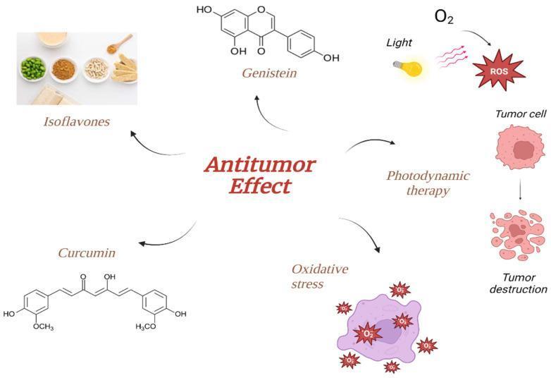
A pathophysiology diagram illustrating various mechanisms contributing to the 'Antitumor Effect,' specifically in the context of thyroid tumor treatment. The central infographic connects three major therapeutic influences: dietary phytochemicals, photodynamic therapy (PDT), and oxidative stress. On the left, phytochemicals are represented by a photograph of soy-based foods labeled 'Isoflavones' and the chemical molecular structures for 'Genistein' and 'Curcumin.' On the right, the mechanism of 'Photodynamic therapy' is depicted, showing the interaction of light and oxygen (O2) to generate reactive oxygen species (ROS), which lead to 'Tumor destruction' via the fragmentation of a tumor cell. The bottom section illustrates 'Oxidative stress' occurring within a cell, marked by multiple ROS icons. This educational schematic highlights the synergistic potential of combining natural plant compounds with light-based interventions to induce apoptosis or cellular disintegration in malignant cells.
A pathophysiology diagram illustrating various mechanisms contributing to the 'Antitumor Effect,' specifically in the context of thyroid tumor treatment. The central infographic connects three major therapeutic influences: dietary phytochemicals, photodynamic therapy (PDT), and oxidative stress. On the left, phytochemicals are represented by a photograph of soy-based foods labeled 'Isoflavones' and the chemical molecular structures for 'Genistein' and 'Curcumin.' On the right, the mechanism of 'Photodynamic therapy' is depicted, showing the interaction of light and oxygen (O2) to generate reactive oxygen species (ROS), which lead to 'Tumor destruction' via the fragmentation of a tumor cell. The bottom section illustrates 'Oxidative stress' occurring within a cell, marked by multiple ROS icons. This educational schematic highlights the synergistic potential of combining natural plant compounds with light-based interventions to induce apoptosis or cellular disintegration in malignant cells.

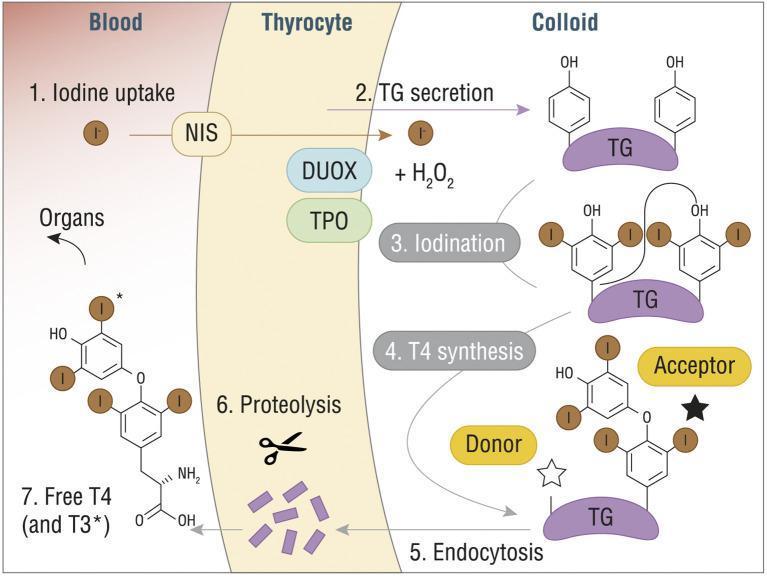
A pathophysiology diagram illustrating the seven-step process of thyroid hormone synthesis (T3 and T4) across three compartments: Blood, Thyrocyte, and Colloid. (1) Iodine uptake: Iodide (I-) enters the thyrocyte from the blood via the Sodium/Iodide Symporter (NIS). (2) TG secretion: Thyroglobulin (TG) is secreted into the colloid. (3) Iodination: Within the colloid, iodide is oxidized by Thyroid Peroxidase (TPO), dual oxidase (DUOX), and H2O2, leading to the attachment of iodine to tyrosine residues on TG. (4) T4 synthesis: A coupling reaction occurs between 'Donor' and 'Acceptor' iodinated tyrosine residues on the TG scaffold. (5) Endocytosis: The modified TG molecule is re-absorbed into the thyrocyte. (6) Proteolysis: Lysosomal enzymes break down TG, releasing individual hormones. (7) Release: Free T4 (thyroxine) and T3 (triiodothyronine) are secreted into the blood for systemic distribution to organs. The diagram includes detailed chemical structures of the phenolic rings and iodine substitutions characteristic of thyroid hormones.
A pathophysiology diagram illustrating the seven-step process of thyroid hormone synthesis (T3 and T4) across three compartments: Blood, Thyrocyte, and Colloid. (1) Iodine uptake: Iodide (I-) enters the thyrocyte from the blood via the Sodium/Iodide Symporter (NIS). (2) TG secretion: Thyroglobulin (TG) is secreted into the colloid. (3) Iodination: Within the colloid, iodide is oxidized by Thyroid Peroxidase (TPO), dual oxidase (DUOX), and H2O2, leading to the attachment of iodine to tyrosine residues on TG. (4) T4 synthesis: A coupling reaction occurs between 'Donor' and 'Acceptor' iodinated tyrosine residues on the TG scaffold. (5) Endocytosis: The modified TG molecule is re-absorbed into the thyrocyte. (6) Proteolysis: Lysosomal enzymes break down TG, releasing individual hormones. (7) Release: Free T4 (thyroxine) and T3 (triiodothyronine) are secreted into the blood for systemic distribution to organs. The diagram includes detailed chemical structures of the phenolic rings and iodine substitutions characteristic of thyroid hormones.

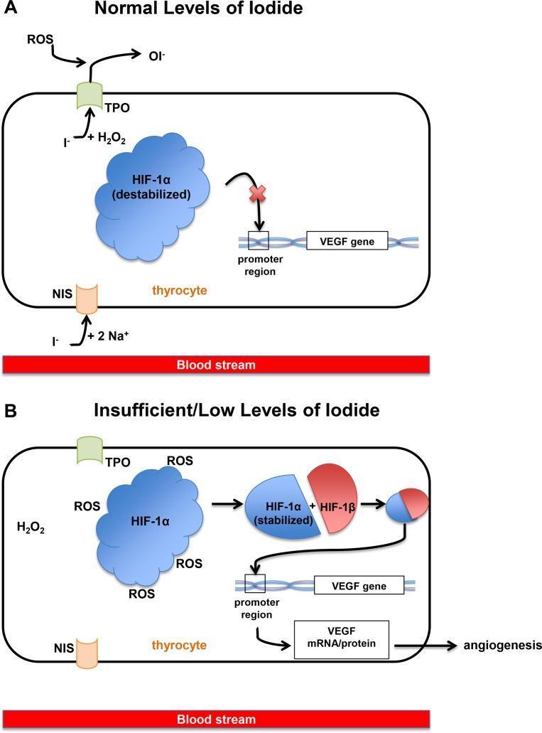
This pathophysiology diagram illustrates the molecular signaling pathways in a thyrocyte under normal (Panel A) versus insufficient iodide conditions (Panel B). In both scenarios, the basolateral membrane shows iodide (I-) entry via the sodium-iodide symporter (NIS). Panel A depicts normal iodide levels where I- reacts with thyroid peroxidase (TPO) and H2O2 at the apical membrane. In this state, Hypoxia Inducible Factor-1α (HIF-1α) is destabilized and unable to bind to the Vascular Endothelial Growth Factor (VEGF) gene promoter, indicated by a red 'X'. Panel B illustrates iodine deficiency, where lack of I- substrate results in high levels of cytoplasmic Reactive Oxygen Species (ROS). These ROS stabilize HIF-1α, facilitating its dimerization with HIF-1β. The resulting heterodimer binds to the VEGF gene promoter, stimulating the transcription and translation of VEGF mRNA/protein. This molecular cascade leads to the clinical outcome of angiogenesis. The diagram highlights how iodine deficiency can independently induce thyroid vascularization via the HIF-1α/VEGF pathway.

This pathophysiology diagram illustrates the molecular signaling pathways in a thyrocyte under normal (Panel A) versus insufficient iodide conditions (Panel B). In both scenarios, the basolateral membrane shows iodide (I-) entry via the sodium-iodide symporter (NIS). Panel A depicts normal iodide levels where I- reacts with thyroid peroxidase (TPO) and H2O2 at the apical membrane. In this state, Hypoxia Inducible Factor-1α (HIF-1α) is destabilized and unable to bind to the Vascular Endothelial Growth Factor (VEGF) gene promoter, indicated by a red 'X'. Panel B illustrates iodine deficiency, where lack of I- substrate results in high levels of cytoplasmic Reactive Oxygen Species (ROS). These ROS stabilize HIF-1α, facilitating its dimerization with HIF-1β. The resulting heterodimer binds to the VEGF gene promoter, stimulating the transcription and translation of VEGF mRNA/protein. This molecular cascade leads to the clinical outcome of angiogenesis. The diagram highlights how iodine deficiency can independently induce thyroid vascularization via the HIF-1α/VEGF pathway.

Let me now get the Tietz section on Graves disease and the escape mechanism, plus Harrison's amiodarone section for more Wolff-Chaikoff detail, and fetch the thyroid hormone synthesis diagram.
Reading File
Loading Image
Finding Sources
I now have excellent material from multiple authoritative textbooks. Let me compile the full, comprehensive answer.

Wolff-Chaikoff Effect in Graves' Disease

1. Normal Thyroid Iodide Physiology (Background)

To understand the Wolff-Chaikoff effect, you need to know the steps of thyroid hormone synthesis:
Thyroid hormone synthesis steps - NIS, TPO, DUOX, thyroglobulin iodination
Iodide enters thyrocytes at the basolateral membrane via the Na+/I- symporter (NIS), accumulating at 20-40x plasma concentration. It exits at the apical border via pendrin (SLC26A4) into the colloid. There, thyroid peroxidase (TPO) uses H2O2 (generated by DUOX) to oxidize iodide and iodinate tyrosine residues on thyroglobulin (TG), forming mono- and diiodotyrosine (MIT, DIT), which then couple to form T3 and T4. - Ganong's Review of Medical Physiology, 26th Ed

2. The Wolff-Chaikoff Effect: Core Mechanism

When plasma iodide rises acutely to supraphysiologic levels, the thyroid gland paradoxically inhibits its own hormone synthesis. This is the Wolff-Chaikoff effect, described in 1948.

Molecular Mechanisms

StepWhat Happens
Iodide floods the thyrocyteIntracellular [I-] surges far above the physiologic range
Inhibition of H2O2 generationExcess iodide suppresses DUOX activity, reducing H2O2 availability
TPO-catalyzed organification is blockedWithout sufficient H2O2, TPO cannot oxidize iodide to iodine for TG iodination
Synthesis of T3/T4 fallsLess MIT/DIT formed; less coupling occurs
TSH rises transientlyFalling T3/T4 triggers pituitary TSH release
"Iodide limits its own transport and acutely and transiently inhibits the synthesis of iodotyrosines and iodothyronines (the Wolff-Chaikoff effect)." - Goodman & Gilman's Pharmacological Basis of Therapeutics
The effect is an autoregulatory protective response that prevents the thyroid from producing excessive hormone when flooded with substrate. - Tietz Textbook of Laboratory Medicine, 7th Ed

3. "Escape" from the Wolff-Chaikoff Effect (Normal Individuals)

In an intact, normal thyroid, the effect is transient - lasting only a few days. The escape mechanism is key to understanding what goes wrong in Graves' disease.
How escape occurs:
  • With continued iodide excess, the thyroid downregulates NIS expression at the basolateral membrane
  • NIS is actively trafficked out of the membrane
  • Intracellular iodide concentration falls back below the inhibitory threshold
  • TPO activity resumes, organification restarts
  • Hormone synthesis normalizes
This escape is TSH-independent - it is a pure intrathyroidal autoregulatory mechanism. - Katzung's Basic & Clinical Pharmacology, 16th Ed; Scott-Brown's Otorhinolaryngology

4. Pathophysiology Specific to Graves' Disease

Graves' disease fundamentally disrupts the Wolff-Chaikoff effect at multiple levels. Here's how:

4a. TSI/TSH-R Ab Overrides Normal Autoregulation

In Graves' disease, thyroid-stimulating immunoglobulins (TSI) - also called TSH-R Ab [stim] - are IgG autoantibodies that:
  • Bind the TSH receptor constitutively
  • Stimulate the gland continuously and with a longer duration than TSH itself
  • Drive NIS upregulation, TPO upregulation, and increased H2O2 generation persistently
Because TSI bypass the normal feedback loops, the gland cannot appropriately downregulate NIS in response to iodide loading. The NIS remains overexpressed, iodide continues flooding the thyrocyte, and the initial Wolff-Chaikoff inhibition may occur - but the escape is accelerated or abnormal. - Katzung's Basic & Clinical Pharmacology, 16th Ed

4b. Failure to Escape - Why Graves' Patients Can Become Hypothyroid on Iodide

Paradoxically, some Graves' disease patients (particularly those with co-existing autoimmune thyroid disease features, or post-treatment) fail to escape the Wolff-Chaikoff effect. This occurs because:
  • Underlying lymphocytic infiltration impairs thyroid autoregulatory mechanisms
  • Damaged thyroid follicles cannot downregulate NIS effectively
  • This is analogous to Hashimoto thyroiditis, where iodide excess causes persistent hypothyroidism
"If the patient has underlying disease (e.g., Hashimoto thyroiditis, Graves disease), escape from the Wolff-Chaikoff effect is less likely, and permanent hypothyroidism can develop." - Tietz Textbook of Laboratory Medicine, 7th Ed

4c. Clinical Exploitation - Preoperative Lugol's Iodine in Graves' Disease

This is one of the most important clinical applications:
When high-dose iodine (Lugol's solution / SSKI) is given preoperatively in Graves' disease:
  1. Wolff-Chaikoff effect - inhibits organification, rapidly decreasing T4/T3 synthesis
  2. Inhibition of hormone release - iodide directly blocks secretion of preformed T3/T4 from colloid (this is rapid and the most clinically important effect in thyrotoxic crisis)
  3. Gland involution - vascularity decreases, follicular cells shrink, colloid reaccumulates - making the gland firmer and less vascular for surgical resection
  4. Maximal effect - occurs at 10-15 days of continuous therapy
"Release of thyroid hormone into the circulation is rapidly blocked, and its synthesis is mildly decreased. In the thyroid gland, vascularity is reduced, the gland becomes much firmer, the cells become smaller, and colloid reaccumulates in the follicles... The maximal effect occurs after 10 to 15 days." - Goodman & Gilman's
However, because Graves' patients will eventually escape the Wolff-Chaikoff block (the TSI-driven gland reasserts its activity), surgery must be performed within that window. Prolonged use allows escape and can precipitate rebound thionamide-resistant thyrotoxicosis. - Scott-Brown's Otorhinolaryngology

5. The Iodine-Induced Hyperthyroidism (Jod-Basedow) Angle

A separate but related phenomenon in Graves' disease:
  • In patients with autonomous functioning nodules or poorly controlled Graves' disease, excess iodide can cause iodine-induced hyperthyroidism (Jod-Basedow phenomenon)
  • Here, the gland fails to mount a Wolff-Chaikoff inhibitory response at all (the autonomous nodules and TSI-driven tissue ignore the inhibitory signal and simply use the extra iodide substrate to make more hormone)
"Hyperthyroidism can result from the loss of the Wolff-Chaikoff block in susceptible individuals (eg, multinodular goiter)." - Katzung's Basic & Clinical Pharmacology, 16th Ed

6. Summary Table: Wolff-Chaikoff Effect Across Clinical Contexts

Clinical StateWolff-Chaikoff BlockEscapeNet Outcome
Normal thyroidNormal (transient inhibition)Occurs in daysEuthyroid
Graves' disease (active, high TSI)Occurs acutelyAccelerated escapeTransient benefit only; hyperthyroid resumes
Graves' + autoimmune damageOccurs acutelyImpaired escapeMay become hypothyroid
Preoperative iodide in Graves'Deliberately exploitedMust operate before escapeReduced bleeding, safer surgery
Hashimoto thyroiditisOccursFails to escapePersistent hypothyroidism
Multinodular goiter / Jod-BasedowAbsent or lostN/AIodine-induced hyperthyroidism

Key Takeaways

  1. The Wolff-Chaikoff effect = supraphysiologic iodide inhibits H2O2 production by DUOX, blocking TPO-mediated organification of iodide into thyroglobulin, acutely suppressing T3/T4 synthesis.
  2. In normal individuals, escape occurs within days via NIS downregulation (intracellular [I-] falls below the inhibitory threshold).
  3. In active Graves' disease, TSI constitutively drives NIS and TPO overexpression - the initial block still occurs, but escape is facilitated by the persistent TSI stimulation, limiting the therapeutic window.
  4. In Graves' disease with coexistent autoimmune damage, escape may fail, causing paradoxical iodine-induced hypothyroidism.
  5. Clinically, Lugol's iodine is used pre-thyroidectomy in Graves' to harness the acute Wolff-Chaikoff effect plus inhibition of hormone release, making the gland smaller, firmer, and less vascular - with the critical caveat that surgery must occur within ~10-14 days before escape.
Sources: Goodman & Gilman's Pharmacological Basis of Therapeutics; Katzung's Basic & Clinical Pharmacology 16e; Ganong's Review of Medical Physiology 26e; Scott-Brown's Otorhinolaryngology Vol 1; Tietz Textbook of Laboratory Medicine 7e; Harrison's Principles of Internal Medicine 22e (2025)

EVD IN NEUROSURGERY

Reading File
Now running parallel searches across the library for all major EVD topics simultaneously.
Finding Sources
Finding Sources
Finding Sources
Good. Now reading the core EVD sections from Bailey & Love and Schwartz's in parallel, plus fetching key images and searching for EVD-specific images.
Reading File
Reading File
Searching Images

external ventricular drain EVD placement neurosurgery ventriculostomy catheter

This intraoperative clinical photograph demonstrates a smartphone-assisted technique for the placement of an external ventricular drain (EVD) in a neurosurgical setting. The surgical site on the patient's scalp is prepared with sterile drapes and marked with purple ink showing the sagittal midline and a curvilinear line representing the coronal insertion plane. A smartphone, encased in a sterile transparent cover, is utilized as a digital protractor to guide the catheter trajectory. The screen displays a real-time angular measurement of 12.0 degrees, used to calibrate the lateral tilt of the surgical instrument. A metallic, graduated ventricular catheter is held by a surgeon in sterile gloves, aligned precisely with the smartphone's indicated axis and the pre-marked insertion point at Kocher's point. The visual demonstrates the integration of mobile health technology in surgical navigation to improve the accuracy of bedside neurosurgical procedures like ventriculostomy by standardizing insertion angles.

This intraoperative clinical photograph demonstrates a smartphone-assisted technique for the placement of an external ventricular drain (EVD) in a neurosurgical setting. The surgical site on the patient's scalp is prepared with sterile drapes and marked with purple ink showing the sagittal midline and a curvilinear line representing the coronal insertion plane. A smartphone, encased in a sterile transparent cover, is utilized as a digital protractor to guide the catheter trajectory. The screen displays a real-time angular measurement of 12.0 degrees, used to calibrate the lateral tilt of the surgical instrument. A metallic, graduated ventricular catheter is held by a surgeon in sterile gloves, aligned precisely with the smartphone's indicated axis and the pre-marked insertion point at Kocher's point. The visual demonstrates the integration of mobile health technology in surgical navigation to improve the accuracy of bedside neurosurgical procedures like ventriculostomy by standardizing insertion angles.

This composite diagnostic image illustrates the placement and verification of an External Ventricular Drain (EVD) in a neurosurgical context. Panel A is a lateral sagittal scout CT image of the head and neck, demonstrating the radiopaque catheter entering the superior aspect of the skull and traversing the brain parenchyma. Panel B and C are axial non-contrast CT scans of the head. In Panel B, the distal end of the hyperdense EVD catheter is visualized within the frontal horn of the lateral ventricle. Panel C shows the catheter tip terminating near the Foramen of Monro, the intended anatomical target for optimal cerebrospinal fluid (CSF) diversion. The images highlight key landmarks including the skull vault, cervical vertebrae, and the ventricular system. This material is pedagogically relevant for training in neurocritical care, radiology, and neurosurgery, specifically for confirming catheter trajectory and tip position post-insertion to manage intracranial pressure or subarachnoid hemorrhage.

This composite diagnostic image illustrates the placement and verification of an External Ventricular Drain (EVD) in a neurosurgical context. Panel A is a lateral sagittal scout CT image of the head and neck, demonstrating the radiopaque catheter entering the superior aspect of the skull and traversing the brain parenchyma. Panel B and C are axial non-contrast CT scans of the head. In Panel B, the distal end of the hyperdense EVD catheter is visualized within the frontal horn of the lateral ventricle. Panel C shows the catheter tip terminating near the Foramen of Monro, the intended anatomical target for optimal cerebrospinal fluid (CSF) diversion. The images highlight key landmarks including the skull vault, cervical vertebrae, and the ventricular system. This material is pedagogically relevant for training in neurocritical care, radiology, and neurosurgery, specifically for confirming catheter trajectory and tip position post-insertion to manage intracranial pressure or subarachnoid hemorrhage.

This diagnostic image is an intraoperative ultrasound (iUS) of the brain in a grayscale, phased-array sector format. The image illustrates neurosurgical guidance for External Ventricular Drain (EVD) placement. Anatomical landmarks include the bilateral lateral ventricles, which appear as hypoechoic (darker) fluid-filled spaces; the right ventricle is marked with an asterisk (*), and the left ventricle is marked with a hash symbol (#). A vertical, white dotted line represents a 'virtual puncture line' or planned trajectory, highlighted by a red arrow indicating the intended path for catheter insertion. Surrounding metadata indicates the use of a 'Probe: 52114P' at a 'Punc: 0°' (puncture angle), with ultrasound settings such as a 3.64 MHz frequency and a gain of 90. This visual serves as a primary educational example of real-time intraoperative guidance to increase the accuracy of catheter placement in neurosurgery, specifically for managing intraventricular hemorrhage or hydrocephalus.

This diagnostic image is an intraoperative ultrasound (iUS) of the brain in a grayscale, phased-array sector format. The image illustrates neurosurgical guidance for External Ventricular Drain (EVD) placement. Anatomical landmarks include the bilateral lateral ventricles, which appear as hypoechoic (darker) fluid-filled spaces; the right ventricle is marked with an asterisk (*), and the left ventricle is marked with a hash symbol (#). A vertical, white dotted line represents a 'virtual puncture line' or planned trajectory, highlighted by a red arrow indicating the intended path for catheter insertion. Surrounding metadata indicates the use of a 'Probe: 52114P' at a 'Punc: 0°' (puncture angle), with ultrasound settings such as a 3.64 MHz frequency and a gain of 90. This visual serves as a primary educational example of real-time intraoperative guidance to increase the accuracy of catheter placement in neurosurgery, specifically for managing intraventricular hemorrhage or hydrocephalus.

Anatomical diagram and procedural illustration of an external ventricular drain (EVD) placement. The primary image shows a transparent skull and brain, revealing the blue lateral ventricles. An EVD catheter is depicted entering through a burr hole at Kocher's point, traversing the brain parenchyma to reach the ipsilateral frontal horn of the lateral ventricle. Two inset boxes provide detail on surgical landmarks and trajectory: the upper inset demonstrates a 90-degree angle of insertion relative to the skull surface to ensure perpendicularity; the lower inset highlights craniometric measurements, showing the entry point 1 cm anterior to the coronal suture and 3 cm lateral to the midline. The catheter is tan-colored with visible black depth markers. This medical illustration serves as a guide for neurosurgical residents and medical students to understand the anatomical relationships and technical requirements for successful ventricular cannulation and intracranial pressure monitoring.

Anatomical diagram and procedural illustration of an external ventricular drain (EVD) placement. The primary image shows a transparent skull and brain, revealing the blue lateral ventricles. An EVD catheter is depicted entering through a burr hole at Kocher's point, traversing the brain parenchyma to reach the ipsilateral frontal horn of the lateral ventricle. Two inset boxes provide detail on surgical landmarks and trajectory: the upper inset demonstrates a 90-degree angle of insertion relative to the skull surface to ensure perpendicularity; the lower inset highlights craniometric measurements, showing the entry point 1 cm anterior to the coronal suture and 3 cm lateral to the midline. The catheter is tan-colored with visible black depth markers. This medical illustration serves as a guide for neurosurgical residents and medical students to understand the anatomical relationships and technical requirements for successful ventricular cannulation and intracranial pressure monitoring.

Excellent images found. Now let me get the ICP management/EVD sections from Schwartz's and Harrison's, plus search for EVD complications and indications.
Reading File
Finding Sources
Finding Sources
Good data from Schwartz's. Now let me get EVD complications, the Harrison's ICP section, and the Fischer's surgery EVD content.
Reading File
Reading File
Finding Sources
Excellent content. Let me fetch the Harrison's ventriculostomy image and search for EVD complications and SAH-specific content.
Loading Image
Finding Sources
Loading Image
I now have comprehensive material. Let me compile the full answer.

External Ventricular Drain (EVD) in Neurosurgery

1. Definition and Basic Concept

An External Ventricular Drain (EVD) - also called a ventriculostomy - is a perforated plastic catheter inserted into the frontal horn of the lateral ventricle through a burr hole. It serves as a temporary, bedside neurosurgical intervention that:
  • Monitors intracranial pressure (ICP) in real time
  • Drains CSF to acutely reduce ICP
  • Allows CSF sampling for laboratory analysis
  • Can deliver intrathecal antibiotics
"A perforated plastic catheter is inserted into the frontal horn of the lateral ventricle. An uninterrupted fluid column through a rigid tube allows transduction of intracranial pressure (ICP). CSF also can be drained to reduce ICP or sampled for laboratory studies." - Schwartz's Principles of Surgery, 11th Ed

2. Anatomy and Surgical Technique

Ventriculostomy diagram showing EVD catheter entering through burr hole into lateral ventricle, with brain tissue oxygen probe and fiberoptic ICP monitor

Kocher's Point - The Standard Entry Site

The EVD is most commonly inserted at Kocher's point:
ParameterMeasurement
Lateral to midline (sagittal suture)2.5-3 cm (right of midline)
Anterior to coronal suture1 cm anterior
SideRight (non-dominant hemisphere preferred)
TrajectoryPerpendicular to brain surface
TargetForamen of Monro, ipsilateral frontal horn
DepthTypically 5-7 cm from skull surface
The right frontal region is preferred to minimize neurological impact from potential complications. A small twist-drill or burr hole is made with a hand-held drill at the bedside or in the OR. - Bailey & Love's Short Practice of Surgery 28th Ed; Fischer's Mastery of Surgery 8th Ed
EVD placement at Kocher's point showing catheter trajectory into frontal horn of lateral ventricle
CT scan verification of EVD catheter tip at foramen of Monro

3. Indications for EVD Placement

A. ICP Monitoring Indications

  • Traumatic brain injury (TBI): GCS 3-8 with abnormal CT (hematoma, contusion, swelling) or GCS 3-8 with normal CT plus two of: age >40, posturing, systolic BP <90 mmHg
  • Subarachnoid hemorrhage (SAH) with coma or neurologic deterioration
  • Intracranial hemorrhage (ICH) with intraventricular blood
  • Ischemic MCA stroke with severe brain edema
  • Fulminant hepatic failure with cerebral edema on CT
  • Global cerebral ischemia with CT edema

B. CSF Drainage / Hydrocephalus

  • Acute obstructive hydrocephalus (e.g., posterior fossa tumors, aqueductal stenosis)
  • SAH-related hydrocephalus - impaired CSF reabsorption at arachnoid granulations
  • Intraventricular hemorrhage (IVH) - blood clots obstructing CSF flow
  • Infected shunt - temporary drainage bridge while treating shunt infection
  • Preoperative/perioperative CSF diversion in anticipation of posterior fossa surgery
"In hydrocephalus from SAH, the principal cause of elevated ICP is impairment of CSF drainage. In this setting, ventricular drainage of CSF is likely to be sufficient and most appropriate." - Harrison's Principles of Internal Medicine, 22nd Ed (2025)

4. ICP Physiology and EVD Targets

The Monro-Kellie Doctrine

The cranium is a rigid closed box with three compartments:
  • Brain tissue (~80%)
  • Blood (~10%)
  • CSF (~10%)
Any increase in one compartment must be compensated by reduction in another. When compensatory capacity is exhausted, ICP rises steeply.

ICP Targets

ParameterTarget Value
Normal ICP4-14 mmHg
ICP treatment threshold>20-22 mmHg
ICP trigger for EVD drainage>22 mmHg
Cerebral Perfusion Pressure (CPP) target≥60 mmHg (typically 60-70 mmHg)
CPP formulaCPP = MAP - ICP
EVD drainage is applied intermittently or continuously when ICP exceeds 22 mmHg. - Fischer's Mastery of Surgery 8th Ed

EVD in the Stepwise ICP Management Protocol (Harrison's, 2025)

When ICP >20-25 mmHg for >5 minutes, the management cascade is:
  1. Elevate head of bed; midline head position
  2. Drain CSF via ventriculostomy (if in place) ← EVD role
  3. Osmotherapy - mannitol 25-100 g q4h, or hypertonic saline (23.4% NaCl 30 mL bolus)
  4. Glucocorticoids (for vasogenic edema from tumor/abscess; avoid in TBI/stroke)
  5. Sedation (morphine, propofol, or midazolam); paralysis if needed
  6. Controlled hyperventilation to PaCO2 30-35 mmHg (short-term only)
  7. Vasopressors to maintain MAP and CPP ≥60 mmHg
  8. Second-tier therapies for refractory ICP (barbiturate coma, decompressive craniectomy)

5. The EVD System - How It Works

The EVD is a closed fluid-column manometry system:
Lateral ventricle → perforated catheter tip
    → fluid column in rigid tubing
    → pressure transducer (zeroed to external auditory meatus / foramen of Monro level)
    → digital ICP readout
    → drainage bag (set at prescribed height above patient's head)
  • The drainage bag height controls passive CSF outflow - raising it reduces drainage, lowering it increases drainage
  • The reference level (zero point) is the foramen of Monro, approximated by the external auditory meatus with the head flat
  • The system can be switched between monitoring mode (closed, measuring ICP) and drainage mode (open, allowing CSF outflow)
  • CSF drainage intermittently at ICP threshold or continuously with a set pressure gradient

6. EVD vs. Intraparenchymal Monitor

FeatureEVD (Ventriculostomy)Intraparenchymal Bolt
ICP accuracyGold standardGood but may drift
CSF drainageYesNo
CSF samplingYesNo
Drug deliveryYes (intrathecal)No
InvasivenessHigherLower
Complication rateSlightly higherLower
Best useTBI, SAH, hydrocephalusWhen ventricles collapsed
"Ventriculostomy catheters are the accepted standard for monitoring ICP in patients with TBI due to their accuracy, ability to drain CSF, and low complication rate." - Schwartz's Principles of Surgery, 11th Ed

7. Complications of EVD

Published Complication Rates (Schwartz's)

ComplicationRate
Infection / Ventriculitis~5%
Hemorrhage (catheter tract)~1.1%
Catheter malfunction / obstruction6.3-10.5%
Malposition / cerebral injuryVariable

Infection (Ventriculitis / Meningitis)

  • Most common serious complication
  • Risk increases with duration (especially beyond 5-7 days)
  • Organisms: Staphylococcus epidermidis, S. aureus, gram-negatives
  • Prevention: strict sterile technique, antibiotic-impregnated catheters, minimizing breaks in the system, avoiding routine catheter changes
  • Treatment: IV antibiotics ± intrathecal antibiotics delivered through the EVD itself; catheter change or removal if colonized

Hemorrhage

  • Tract hemorrhage at insertion; usually small and clinically silent
  • Risk factors: coagulopathy, thrombocytopenia, difficult pass

Obstruction

  • Clotted blood or debris in catheter tip (common in IVH)
  • Can sometimes be cleared by gentle flushing (strict sterile protocol)

Overdrainage

  • Excessive CSF removal causes slit ventricles, brain herniation upward through tentorial notch, or subdural hematoma from bridging vein tearing
  • Prevented by careful height adjustment of drainage bag

Malposition

  • Catheter tip in brain parenchyma rather than ventricle
  • CT confirmation post-insertion mandatory

8. EVD in Specific Neurosurgical Conditions

Traumatic Brain Injury (TBI)

  • Inserted within 4 hours of injury in GCS 3-8 patients with CT evidence of DAI or brain swelling
  • Applied intermittently or continuously for ICP >22 mmHg
  • Combined with maximal medical management: euthermia, BP support, sedation, moderate hyperventilation (PCO2 ~30 mmHg), osmotherapy
  • If sustained ICP ~25 mmHg despite EVD, consider decompressive craniectomy

Subarachnoid Hemorrhage (SAH)

  • EVD placed urgently for acute hydrocephalus (blood blocking CSF pathways)
  • Improves clinical grade preoperatively in poor-grade SAH patients
  • Potential risk of aneurysm re-rupture with rapid ventricular decompression - avoid aggressive drainage if aneurysm unsecured

Intraventricular Hemorrhage (IVH)

  • EVD the primary intervention for clot-related obstructive hydrocephalus
  • Intraventricular thrombolysis (rtPA) via EVD may be used to accelerate clot clearance (CLEAR trial data)

Posterior Fossa Tumors / Obstructive Hydrocephalus

  • Early EVD for obstructive hydrocephalus is critical - these patients can deteriorate rapidly from tonsillar herniation
  • May be placed preoperatively, perioperatively, or as a bridge to definitive tumor resection

Infected VP Shunt

  • EVD placed as temporary CSF diversion while the infected shunt is removed and antibiotics are given
  • A new permanent shunt is inserted only after CSF cultures clear

9. EVD vs. Lumbar Drain

FeatureEVDLumbar Drain
CSF diversionVentricularLumbar subarachnoid
ICP monitoringYes (direct)Not reliable
Safe in obstructive hydrocephalusYesContraindicated (risk of tonsillar herniation)
Use in SAHYesYes (communicating SAH)
Intrathecal drug deliveryYesYes
Insertion difficultyModerate (requires burr hole)Lower

10. Summary

The EVD is the gold standard for simultaneous ICP monitoring and CSF drainage in neurocritical care. Its therapeutic value lies in directly reducing CSF volume - the one most controllable component within the rigid cranium - with immediate effect on ICP. Correct positioning at Kocher's point targeting the foramen of Monro, strict sterile maintenance, careful drainage height management, and prompt recognition of complications are the pillars of safe EVD care.
Sources: Bailey & Love's Short Practice of Surgery 28th Ed; Schwartz's Principles of Surgery 11th Ed; Harrison's Principles of Internal Medicine 22nd Ed (2025); Fischer's Mastery of Surgery 8th Ed; Goodman & Gilman's Pharmacological Basis of Therapeutics

EVD IN NEUROSURGERY

I just covered EVD in neurosurgery comprehensively in the previous response. Here's the full summary for reference:

External Ventricular Drain (EVD) in Neurosurgery

Definition

An EVD (ventriculostomy) is a perforated plastic catheter inserted into the frontal horn of the lateral ventricle through a burr hole. It simultaneously:
  • Monitors ICP in real time
  • Drains CSF to reduce ICP
  • Allows CSF sampling
  • Delivers intrathecal drugs

Surgical Anatomy - Kocher's Point

EVD placement at Kocher's point showing catheter trajectory into frontal horn
LandmarkMeasurement
Lateral to sagittal suture2.5-3 cm (right side preferred)
Anterior to coronal suture1 cm
TrajectoryPerpendicular to skull surface
TargetForamen of Monro, frontal horn
Depth~5-7 cm from skull
Right frontal placement minimizes deficit risk from complications.

Indications

ICP Monitoring

  • TBI - GCS 3-8 with abnormal CT; or normal CT + 2 of: age >40, posturing, SBP <90
  • SAH - coma or neurologic deterioration
  • ICH - with intraventricular blood
  • Ischemic MCA stroke - severe edema
  • Fulminant hepatic failure - cerebral edema on CT

CSF Drainage / Hydrocephalus

  • Acute obstructive hydrocephalus (posterior fossa tumors, aqueductal obstruction)
  • SAH-related hydrocephalus
  • Intraventricular hemorrhage (IVH)
  • Infected VP shunt (temporary bridge)
  • Pre/perioperative CSF diversion

ICP Physiology & Targets

Monro-Kellie Doctrine: Skull is a rigid box - brain (~80%) + blood (~10%) + CSF (~10%). When compensatory capacity fails, ICP rises sharply.
ParameterTarget
Normal ICP4-14 mmHg
Treatment threshold>20-22 mmHg
CPP target≥60 mmHg
FormulaCPP = MAP - ICP

How the EVD System Works

Ventriculostomy and ICP monitoring diagram from Harrison's 2025
Frontal horn → perforated catheter tip
  → fluid column (rigid tubing)
  → pressure transducer (zeroed to foramen of Monro / external auditory meatus)
  → digital ICP display
  → drainage bag (height controls passive CSF outflow)
  • Monitor mode: system closed, reading ICP
  • Drain mode: system open, CSF draining passively against set bag height
  • Drainage applied intermittently or continuously when ICP >22 mmHg

Stepwise ICP Management (Harrison's 2025)

When ICP >20-25 mmHg for >5 min:
  1. Head of bed elevation; midline head position
  2. Drain CSF via EVD ← primary role
  3. Osmotherapy - mannitol 25-100 g q4h OR hypertonic saline (23.4%, 30 mL bolus)
  4. Sedation (propofol / midazolam / morphine); paralysis if needed
  5. Glucocorticoids - only for tumor/abscess vasogenic edema (avoid in TBI/stroke)
  6. Controlled hyperventilation - PaCO2 30-35 mmHg (short-term bridge only)
  7. Vasopressors to maintain CPP ≥60 mmHg
  8. Refractory ICP - barbiturate coma or decompressive craniectomy

EVD vs. Intraparenchymal Monitor

FeatureEVDBolt/Intraparenchymal
ICP accuracyGold standardGood (may drift)
CSF drainageYesNo
CSF samplingYesNo
Intrathecal drug deliveryYesNo
InvasivenessHigherLower
Best whenVentricles visibleVentricles slit/collapsed
"Ventriculostomy catheters are the accepted standard for monitoring ICP in TBI due to their accuracy, ability to drain CSF, and low complication rate." - Schwartz's Principles of Surgery, 11th Ed

Complications

ComplicationRate
Ventriculitis / infection~5%
Hemorrhage (catheter tract)~1.1%
Obstruction / malfunction6.3-10.5%
MalpositionVariable

Key Points Per Complication

Infection:
  • Risk rises with duration (>5-7 days)
  • Organisms: S. epidermidis, S. aureus, gram-negatives
  • Prevention: antibiotic-impregnated catheters, sterile technique, minimize system breaks
  • Treatment: IV ± intrathecal antibiotics via EVD; remove/replace if colonized
Hemorrhage:
  • Usually small tract bleed, often asymptomatic
  • Risk increases with coagulopathy - correct INR/platelets before insertion
Obstruction:
  • Common in IVH (blood/clot in tip)
  • Careful sterile flushing protocol; may need catheter replacement
Overdrainage:
  • Slit ventricles, upward herniation, subdural hematoma from bridging vein tearing
  • Prevent by appropriate drainage bag height and threshold settings

EVD in Specific Conditions

Traumatic Brain Injury

  • Insert within 4 hours in GCS 3-8 + compatible CT
  • Combined with maximal medical management (sedation, euthermia, osmotherapy, moderate hyperventilation PCO2 ~30 mmHg)
  • Sustained ICP ~25 mmHg despite EVD → consider decompressive craniectomy

Subarachnoid Hemorrhage

  • Urgent EVD for acute hydrocephalus
  • Improves clinical grade pre-aneurysm securing
  • Caution: rapid decompression risks re-rupture if aneurysm unsecured - drain cautiously

Intraventricular Hemorrhage

  • Primary intervention for obstructive hydrocephalus
  • Intraventricular thrombolysis (rtPA via EVD) may accelerate clot resolution

Posterior Fossa Tumors

  • Early EVD prevents rapid tonsillar herniation from obstructive hydrocephalus
  • Bridge to definitive tumor resection

Infected VP Shunt

  • EVD = temporary diversion while infected shunt removed + antibiotics given
  • Reinsertion of new shunt only after CSF cultures clear

EVD vs. Lumbar Drain

FeatureEVDLumbar Drain
ICP monitoringDirect, reliableUnreliable
Obstructive hydrocephalusSafeContraindicated - herniation risk
Communicating hydrocephalus/SAHYesYes
InsertionBurr hole (moderate)Simple, bedside

Key Numbers to Remember

ValueSignificance
ICP >20 mmHgAssociated with poor outcomes in TBI
ICP >22 mmHgEVD drainage threshold
CPP ≥60 mmHgTarget for brain perfusion
5%EVD infection rate
10-15 daysMaximum safe duration before infection risk rises sharply
2.5-3 cm lateral, 1 cm anterior to coronal sutureKocher's point
Sources: Bailey & Love's 28th Ed; Schwartz's Principles of Surgery 11th Ed; Harrison's Principles of Internal Medicine 22nd Ed (2025); Fischer's Mastery of Surgery 8th Ed
This is a shared conversation. Sign in to Orris to start your own chat.