
Mandibular fractures in detail according to standard ENT textbook, include each and everything in it, types of fractures (horizontal and vertical), mandibular plating also. In very simplified manner along with images that are to be drawn in exams
mandibular fracture classification diagram types
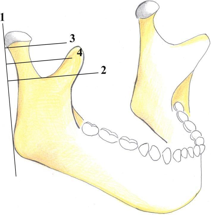
This medical anatomical diagram illustrates the AO Foundation's classification system for mandibular condyle fractures. The illustration depicts a lateral view of a human mandible, focusing on the condylar process, coronoid process, sigmoid notch, and mandibular angle. Four reference lines are utilized to categorize fracture locations: Line 1 is a vertical tangent to the posterior border of the condylar head and mandibular angle; Line 2 is horizontal and perpendicular to Line 1, passing through the deepest point of the sigmoid notch; Line 3 is parallel to Line 2, passing through the inferior margin of the condylar head; and Line 4 is situated equidistant between Lines 2 and 3. In this classification, fractures occurring above Line 3 are 'condylar head' fractures. Fractures between Line 3 and Line 4 are classified as 'high-neck' fractures, while those between Line 4 and Line 2 are 'low-neck' fractures. This standardized mapping aids oral and maxillofacial surgeons in diagnostic reporting and surgical planning for condylar injuries.
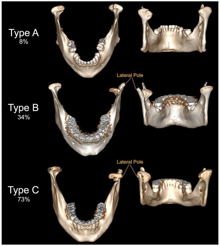
This diagnostic comparison chart features 3D reconstructions of the human mandible, demonstrating the Neff classification of mandibular head fractures. The content is organized into three rows, labeled Type A, Type B, and Type C, with percentages indicating clinical incidence. Each row provides a superior view and a posterior-oblique view of the mandible. Type A (8%): The fracture line involves the articular surface near the medial pole, with minimal structural displacement. Type B (34%): The fracture line is localized at the medial pole of the mandibular head, while the lateral pole remains anatomically intact and connected to the ramus. Type C (73%): The fracture line occurs below the lateral pole. This results in the detachment and anteroinferior displacement of the entire mandibular head (including the lateral pole) from the distal mandibular fragment. Labels highlight the 'Lateral Pole' to emphasize its varying integrity across the three types. This educational material is designed for maxillofacial surgery and radiology indexing, illustrating biomechanical outcomes of condylar process trauma.
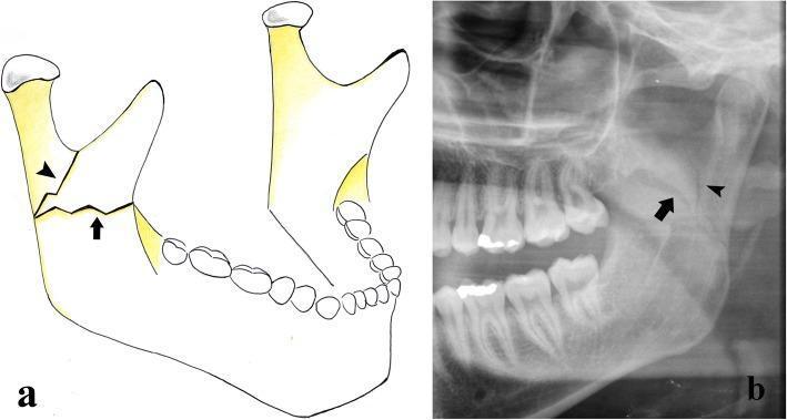
This dual-panel educational figure illustrates types of mandibular ramus fractures through an anatomical diagram and a diagnostic radiograph. Panel A is a schematic anatomical diagram of the mandible showing two primary fracture orientations. An arrowhead indicates a vertical fracture line extending superiorly toward the sigmoid notch, while a black arrow identifies a transverse horizontal fracture line across the mid-ramus. Panel B is a cropped panoramic radiograph (orthopantomogram) demonstrating a combined fracture of the left mandibular ramus. The radiopaque fracture line originates from the posterior/external border of the ramus. Similar to the diagram, it exhibits a complex morphology with both a vertical component (arrowhead) extending toward the condylar process and a horizontal component (arrow) extending anteriorly toward the coronoid process. The imaging displays a clear disruption in cortical continuity. These visuals serve to teach the classification of ramus fractures, which are typically caused by direct high-energy trauma and categorized based on the direction of the fracture rhyme (vertical, horizontal, or combined).
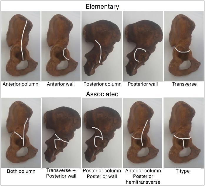
Educational diagram illustrating the Judet-Letournel classification of acetabular fractures using anatomical specimens of the hemipelvis. The visual is divided into two rows: 'Elementary' and 'Associated' fracture types. White lines superimposed on the specimens delineate specific fracture patterns. The 'Elementary' row features five simple patterns: Anterior column (vertical line through the pelvic brim), Anterior wall (localized articular segment), Posterior column (ischiadic notch through obturator foramen), Posterior wall (localized posterior rim), and Transverse (horizontal line bisecting the acetabulum). The 'Associated' row demonstrates complex configurations: Both column, Transverse plus posterior wall, Posterior column plus posterior wall, Anterior column with posterior hemitransverse (a vertical anterior column line joined by a horizontal posterior component), and T-type (a transverse fracture with an additional vertical stem extending through the obturator foramen). This orthopedic diagram serves as a clinical reference for orthopedic surgeons and medical students to understand pelvic trauma morphology and surgical planning.
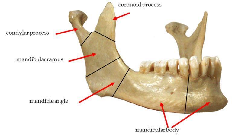
This clinical photograph displays a lateral view of a human mandible, used to illustrate the common anatomical zones for fracture classification. Black demarcating lines and red arrows label five primary regions: 1) The condylar process at the posterosuperior apex, representing the articular portion of the temporomandibular joint. 2) The coronoid process, a sharp, triangular projection anterior to the condyle. 3) The mandibular ramus, the vertical quadrilateral plate connecting the processes to the lower jaw. 4) The mandibular angle, located at the junction of the posterior and inferior borders. 5) The mandibular body, the horizontal portion extending anteriorly and housing the dentition. The image shows the alveolar ridge with integrated teeth and the mental foramen on the lateral surface of the body. This diagram serves as an educational tool for maxillofacial surgery and traumatology, specifically for identifying fracture locations such as subcondylar, ramus, angle, and body fractures.
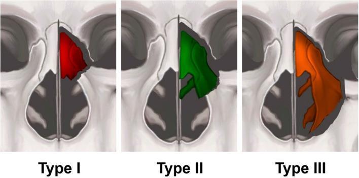
This medical illustration presents an anatomical classification of pyriform buttress fractures, categorized into three types based on the level of the fracture line and subsequent structural collapse within the nasal cavity. The diagram uses a coronal view of the midface to highlight the affected areas in color-coded segments. Type I (red) represents a high fracture line involving the upper third of the nasal pyramid, leading to collapse of the upper nasal vault. Type II (green) illustrates an intermediate fracture line passing through the bone attachment of the middle turbinate, resulting in a more extensive collapse of the upper two-thirds of the nasal vault. Type III (orange) demonstrates a low fracture line extending to the base of the pyriform rim, causing total collapse of the ipsilateral nasal wall and involving both the middle and inferior turbinates. This classification system is crucial for evaluating midfacial trauma, assessing airway obstruction, and planning surgical reconstruction in otorhinolaryngology and maxillofacial surgery.
mandibular plating fixation plate osteosynthesis jaw
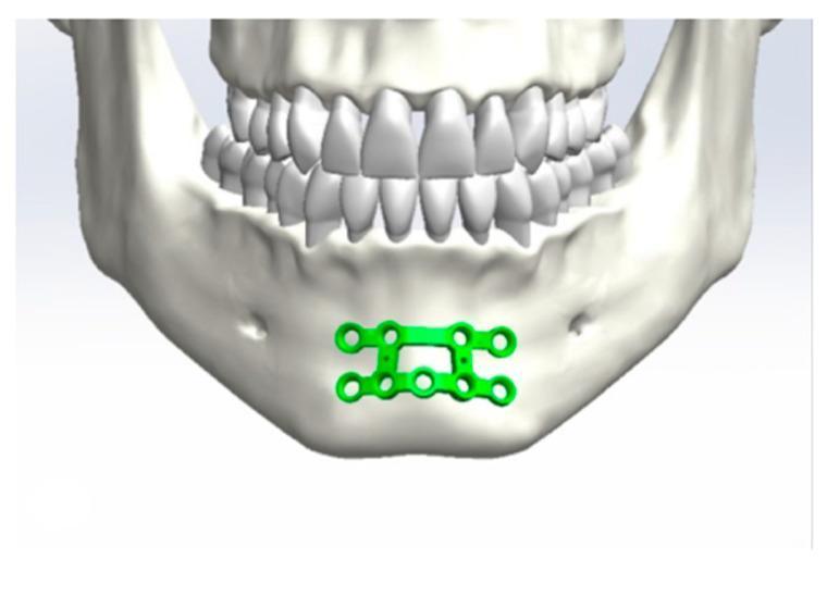
This anatomical diagram and simulation frame illustrates the application of internal fixation hardware in maxillofacial surgery. The image depicts an anterior view of a human skull focuses on the mandible (lower jaw) and dentition. A bright green osteosynthesis miniplate system is shown positioned over the mandibular symphysis. The hardware consists of a dual-plate configuration connected by vertical bars, forming a stable rectangular frame with multiple circular screw holes for rigid fixation. The plate is situated inferior to the roots of the mandibular incisors and cuspids, maintaining a safe distance from the dental apices to prevent trauma during screw insertion. This visualization demonstrates a common surgical approach for the management of mandibular midline or parasymphyseal fractures, highlighting the anatomical relationship between the mental protuberance, alveolar process, and the fixation device. The target educational focus is the biomechanical stabilization of the mandible and the anatomical landmarks essential for plate positioning in oral and maxillofacial trauma surgery.
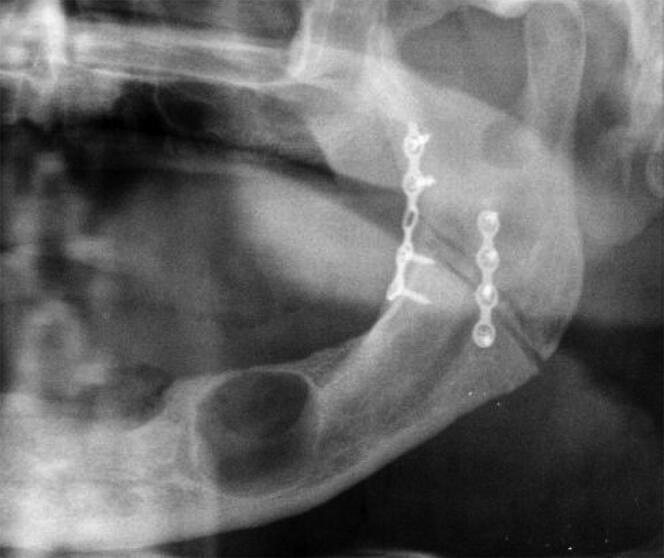
This diagnostic image is a cropped view of a panoramic dental X-ray (orthopantomogram) focusing on the left mandible. The radiograph reveals metallic osteosynthesis hardware used for internal fixation of a mandibular fracture at the left angle and ascending ramus. Two distinct, relatively straight mini-plates are visible: a superior/posterior plate with four holes secured by four screws, and an inferior/anterior plate with five holes secured by five screws. Parallel to this hardware, a significant pathological finding is noted in the inferior body of the mandible: a well-circumscribed, oval-shaped radiolucent lesion with smooth borders, consistent with a mandibular cyst. The surrounding bone shows varying radiodensity, and the jaw appears edentulous. This visual is significant for oral and maxillofacial surgery and forensic odontology, illustrating both post-surgical trauma management (open reduction and internal fixation) and concurrent intraosseous pathology.
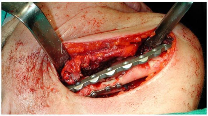
This clinical photograph captures an intra-operative view of a maxillofacial surgical procedure involving the reconstruction of the mandible. The surgical site is accessed through an external submandibular incision, with metallic retractors providing exposure of the mandibular bone. A silver-colored, multi-hole mandibular fixation plate is positioned along the mandibular corpus to provide stabilization and osteosynthesis. Four metallic screws are visible securing the inferior aspect of the plate to the bone. The surgical field shows signs of piezosurgery-based resection, with exposed bone segments aligned by the hardware. Surrounding soft tissues, including skin and subcutaneous fat, appear erythematous with expected minor surgical bleeding. The procedure is part of the management of Medication-Related Osteonecrosis of the Jaw (MRONJ), specifically addressing a stage III lesion that resulted in a mandibular fracture. This image serves as a clinical reference for mandibular reconstruction techniques and hardware placement in oral and maxillofacial surgery.
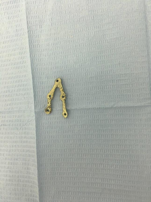
A clinical photograph displaying a customized, milled V-pattern osteosynthesis plate for maxillofacial surgery, specifically designed for mandibular angle fracture fixation. The plate is made of medical-grade titanium with a gold-colored surface finish. It features a characteristic 'V' shape with two divergent arms of unequal length: the longer arm contains three circular screw holes, while the shorter arm contains two screw holes, totaling five apertures for 2 mm bone screws. The plate surface exhibits a slightly irregular, hammered texture resulting from the computer-aided manufacturing (CAM) milling process. This patient-specific implant is designed to align fractured segments while avoiding vital anatomical structures such as the inferior alveolar nerve and tooth apices. The plate is shown resting on a blue sterile surgical drape, highlighting its use in a clinical or laboratory setting.
Mandibular Fractures - Complete ENT/Surgery Guide
1. Anatomy Basics (Draw This First in Exams)
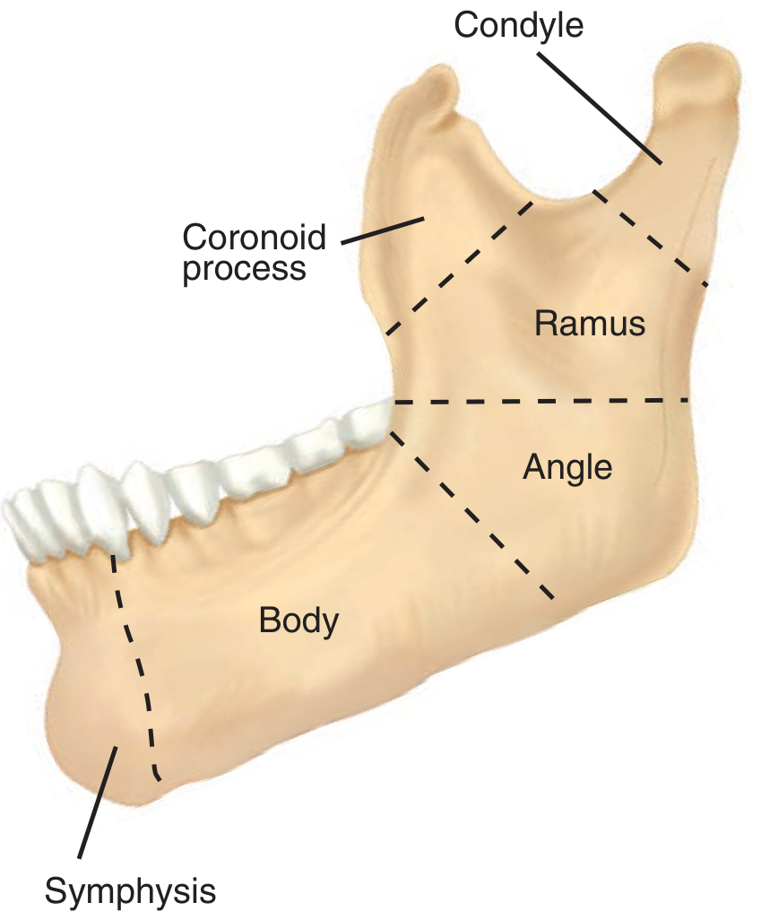
| Region | Description |
|---|---|
| Symphysis | Anterior midline (chin) |
| Parasymphysis | Between midline and mental foramen |
| Body | Horizontal tooth-bearing portion |
| Angle | Junction of body and ramus (where wisdom tooth sits) |
| Ramus | Vertical plate posteriorly |
| Condylar process | Articulates with temporal bone at TMJ |
| Coronoid process | Anterior superior projection; temporalis muscle attaches here |
| Subcondylar (condylar neck) | Narrowest, most fracture-prone region |
2. Incidence and Mechanism
- Mandibular fractures are the 2nd most common facial fracture after nasal fractures
- Mandible is the only mobile facial bone and therefore vulnerable
- Causes: Assault (most common), road traffic accidents, falls, sports injuries
- Because the mandible is a ring structure, fractures are almost always bilateral - one at the impact site, one contralaterally
- Rule: Always consider a mandibular fracture bilateral until proven otherwise
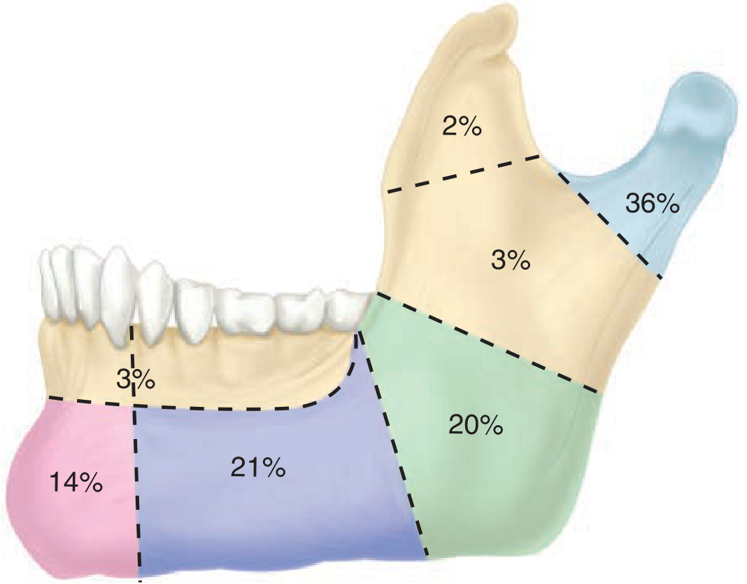
| Site | Approximate Frequency |
|---|---|
| Condyle / subcondylar | 36% (most common) |
| Body | 21-35% |
| Angle | 20% |
| Parasymphysis | 14-17% |
| Symphysis | 3% |
| Ramus | 3% |
| Coronoid | 2% |
3. Classification of Mandibular Fractures
A. By Location (Anatomical Classification)
- Symphyseal - at the midline
- Parasymphyseal - between midline and mental foramen
- Body - tooth-bearing area, between mental foramen and angle
- Angle - third molar region (wisdom tooth); where muscles exert strong forces
- Ramus - vertical portion below condyle
- Condylar/Subcondylar - most common; at neck of condyle or head
- Coronoid - rare, isolated; due to temporalis muscle pull
B. Favorable vs Unfavorable Fractures (Most Important Classification for Exams!)
Horizontal (Buccolingual) Plane - Favorable/Unfavorable
| Favorable | Unfavorable | |
|---|---|---|
| Definition | Muscle pull keeps fragments together | Muscle pull distracts fragments apart |
| Direction | Fracture runs upward and forward (buccolingual) | Fracture runs downward and forward |
| Outcome | Fragments compress together | Fragments distract = gaping, displacement |
| Management | May be managed conservatively | Requires ORIF (open reduction and internal fixation) |
Vertical (Anteroposterior) Plane - Favorable/Unfavorable
| Favorable | Unfavorable | |
|---|---|---|
| Direction | From anterior-lingual to posterior-buccal | From anterior-buccal to posterior-lingual |
| Muscle effect | Masseter/medial pterygoid compress fragments | Same muscles distract fragments |
- Favorable = fragments are pushed together by muscle pull
- Unfavorable = fragments are pulled apart by muscle pull
C. By Nature of the Fracture
| Type | Description |
|---|---|
| Simple (Closed) | Skin/mucosa intact over fracture |
| Open (Compound) | Communication with oral mucosa or skin. Most mandibular fractures through the tooth-bearing area are open due to mucosal lining |
| Comminuted | Multiple bone fragments |
| Greenstick | Incomplete fracture (in children); one cortex bends, other intact |
| Pathological | Through diseased bone (tumor, cyst, osteoradionecrosis) |
| Multiple | Two or more sites fractured |
D. Ramus Fractures - Horizontal and Vertical Types
- Vertical fracture - runs superiorly toward the sigmoid notch (arrowhead in diagram)
- Horizontal fracture - runs transversely across the mid-ramus (arrow in diagram)
- Combined - both components present
- Ramus is well-protected by thick masseter and medial pterygoid muscles
- Coronoid process is protected by the zygomatic arch
- Condylar neck acts as a "safety valve" - fractures there before ramus
E. Condylar Fractures - AO Classification
- Above Line 3 = Condylar head fracture (intracapsular)
- Between Lines 3 and 4 = High condylar neck (subcondylar)
- Between Lines 4 and 2 = Low condylar neck (subcondylar)
- Type A (8%) - medial pole fracture, minimal displacement
- Type B (34%) - medial pole fracture, lateral pole intact
- Type C (73%) - entire head displaced including lateral pole (worst)
- Most common site overall (36%)
- Most common in children (condyle = "crumple zone" for pediatric mandible)
- Bilateral condylar fractures cause anterior open bite (back teeth meet first; cannot close front teeth)
- Unilateral condylar fracture: mandible deviates to ipsilateral side on opening
- Children treated conservatively (2-3 weeks MMF only) to avoid ankylosis
- Risk of TMJ ankylosis if not treated promptly in children
4. Muscles of Mastication and Their Role in Displacement
| Muscle | Attachment | Effect on Fracture |
|---|---|---|
| Masseter | Ramus + angle (external) | Pulls angle UP and INWARD |
| Medial pterygoid | Ramus + angle (internal) | Pulls angle UP and INWARD |
| Temporalis | Coronoid process | Pulls coronoid UP |
| Lateral pterygoid | Condylar neck | Pulls condyle FORWARD and MEDIALLY |
| Geniohyoid/Mylohyoid | Anterior mandible (symphysis) | Pull symphysis DOWN and BACKWARD |
5. Clinical Features (Symptoms and Signs)
- Pain in jaw, worsened by movement
- Malocclusion - teeth don't fit together (most important sign)
- Trismus (limited mouth opening <35 mm) due to pain/muscle spasm
- Numbness of lower lip/chin (inferior alveolar nerve injury)
- Inability to chew
- Step deformity palpable along inferior mandibular border
- Sublingual hematoma (characteristic of body/symphyseal fractures)
- Ecchymosis in floor of mouth
- Abnormal dental occlusion on visual inspection
- Malocclusion - key sign; patient says "teeth don't meet properly"
- Laceration over chin or cheek
- Bony crepitus on palpation
- Tenderness and swelling over fracture site
- Deviation of chin to affected side (in condylar fractures)
6. Angle Classification of Occlusion (Must Know for Exams)
| Class | Description | Position |
|---|---|---|
| Class I | Normal | Mesial buccal cusp of upper 1st molar fits in intercuspal groove of lower 1st molar |
| Class II | Mesial (overjet) | Upper teeth are forward of normal |
| Class III | Distal (underbite) | Upper teeth are behind normal; "bulldog" appearance |
7. Investigations
- OPG (Orthopantomogram / Panorex) - First-line imaging; single X-ray shows entire mandible
- CT face with 3D reconstruction - Gold standard for complex/condylar/comminuted fractures
- PA mandible view
- Lateral oblique views
- Chest X-ray - In unconscious patients with missing teeth (to exclude aspiration)
8. Management
Goals of Treatment
- Restore dental occlusion (Class I)
- Fracture reduction and stable fixation
- Soft tissue repair and wound closure
- Maintain mandibular continuity
Non-surgical Treatment
- Minimally displaced fractures
- Preserved pre-traumatic occlusion
- Normal range of motion
- No significant soft tissue injury
- Condylar fractures in children
- Barton's bandage - Ace wrap over head and under mandible; temporary support; pain relief
- Soft diet for non-displaced fractures
Surgical Treatment
Maxillomandibular Fixation (MMF) / Intermaxillary Fixation (IMF)
- Apply arch bars to both maxillary and mandibular teeth using circumferential wires
- Wire the upper and lower arch bars together (using interdental wires)
- This locks jaws together, immobilizing the fracture
- Adults: 4-6 weeks
- Elderly: 6-8 weeks
- Children/condylar fractures: 2-3 weeks (shorter to prevent ankylosis)
Open Reduction and Internal Fixation (ORIF)
- Open fractures
- Comminuted fractures
- Displaced fractures
- Unfavorable fractures
- Failed closed reduction
- Multiple fractures
- Transcervical (external) - submandibular incision; most common for body/angle
- Transoral (intraoral) - for symphysis, parasymphysis
- Preauricular - for condylar fractures
- Retromandibular - posterior ramus
9. Mandibular Plating - In Detail
Types of Fixation Systems
1. AO/ASIF Rigid Fixation (Association for Osteosynthesis)
- Principle: Absolute stability with rigid, load-bearing plates
- Plates must be strong enough to bear ALL masticatory forces
- Uses large/reconstruction plates (2.4-2.7 mm screws)
- MMF removed immediately after plating; immediate function allowed
- Better for comminuted and edentulous mandible fractures
2. Champy's Principle (Miniplate Fixation)
- Principle: Relative stability via placement along the "ideal lines of osteosynthesis"
- Uses smaller miniplates (2.0 mm screws)
- Based on tension band principle
Champy's Lines of Osteosynthesis (Exam Diagram)
- Symphysis/parasymphysis: TWO plates (one along the alveolar border to neutralize tension, one at the inferior border for torsional forces)
- Body: Single plate along the superior border (below tooth roots)
- Angle: Single plate along the oblique line (external oblique ridge) - "Champy's ideal line"
Types of Plates Used
| Plate Type | Use | Size |
|---|---|---|
| Miniplate | Body, angle, symphysis (Champy's) | 2.0 mm screws |
| Reconstruction plate | Comminuted, edentulous, load-bearing | 2.4-2.7 mm screws |
| Dynamic Compression Plate (DCP) | Rigid fixation; screw holes designed to compress fragments | 2.4 mm |
| Locking plate | For osteoporotic or poor-quality bone | Variable |
| 3D plates | Grid-shaped; better stability | 2.0 mm |
Titanium vs Stainless Steel
- Titanium: Preferred - biocompatible, MRI-safe, corrosion-resistant, low infection rate, no removal needed in most cases
- Stainless steel: Cheaper, needs removal
Plating at the Angle
- Champy's method: Single miniplate placed along the external oblique ridge (superior-posterior border) via intraoral approach
- Two-plate fixation: Superior tension band plate + inferior border plate (more rigid)
- V-shaped plates are sometimes used for biomechanical advantage
Symphyseal/Parasymphyseal Plating
- Requires two plates due to torsional forces at the midline
- Superior plate: along alveolar crest (tension zone)
- Inferior plate: along inferior border (compression zone)
- Plates placed below tooth apices to avoid root damage
Intraoperative Plating Steps
- Apply MMF first to establish correct occlusion
- Expose fracture through appropriate incision
- Reduce fracture manually (confirm occlusion maintained)
- Bend plate to conform exactly to bone contour
- Drill holes (2 screws each side of fracture minimum)
- Insert screws - bicortical for load-bearing plates, monocortical for miniplates
- Remove MMF (if rigid fixation) or retain (if semi-rigid)
- Close wound in layers
10. Complications
Early Complications
- Airway compromise (bilateral fractures, comminuted symphysis - tongue falls back)
- Hemorrhage (inferior alveolar artery injury)
- Nerve injury (inferior alveolar nerve - numbness of chin/lower lip)
Late Complications
- Malocclusion - failed to restore occlusion
- Non-union - failure of bone healing (especially in infected/comminuted fractures)
- Malunion - healed in wrong position
- Osteomyelitis - infection, especially with plates
- TMJ Ankylosis - especially in children with condylar fractures not treated promptly
- Plate failure - plate fracture or screw loosening
- Inferior alveolar nerve damage - permanent numbness
- Trismus - restricted jaw opening post-injury
11. Special Situations
Pediatric Mandibular Fractures
- Condyle is the most common fracture site in children
- Managed conservatively (MMF 2-3 weeks only)
- Key complication: TMJ ankylosis - can cause facial growth disturbance
- Greenstick fractures common
Edentulous Mandible Fractures
- No teeth for MMF application
- Dentures can be wired to bone as "Gunning splints"
- Bone is atrophic (especially after age 60) - load-bearing plates required
- Healing slower; 6-8 weeks minimum
12. Summary Diagram for Exams - What to Draw
- Symphysis (midline)
- Parasymphysis (between midline and mental foramen)
- Body
- Angle (where 3rd molar is)
- Ramus
- Condylar process / condylar head / condylar neck
- Coronoid process
- Sigmoid notch
- Favorable fracture: line going postero-superiorly (muscles compress)
- Unfavorable fracture: line going antero-inferiorly (muscles distract)
- Horizontal line (transverse across ramus)
- Vertical line (toward sigmoid notch)
- Champy's line at angle (on external oblique ridge)
- Two plates at symphysis
- Single plate at body
Key Exam Facts (Quick Recap)
| Fact | Answer |
|---|---|
| Most common facial fracture | Nasal bone |
| 2nd most common | Mandible |
| Most common site of mandibular fracture | Condyle/subcondylar (36%) |
| Most common in children | Condylar fracture |
| "Ring fracture" principle | Always bilateral; 2nd fracture often contralateral |
| Key diagnostic sign | Malocclusion |
| First-line imaging | OPG (Panorex) |
| Favorable fracture | Muscles compress fragments |
| Unfavorable fracture | Muscles distract fragments |
| MMF duration (adults) | 4-6 weeks |
| MMF duration (children/condyle) | 2-3 weeks (to avoid ankylosis) |
| Champy's plate location for angle | External oblique ridge (superior) |
| Symphysis requires | 2 plates (tension + compression zones) |
| Most important nerve at risk during surgery | Marginal mandibular branch of facial nerve |
| Complication in children if undertreated | TMJ ankylosis + facial growth disturbance |