What is rouviere sulcus and R4U line Explain with diagram
Rouviere sulcus laparoscopic cholecystectomy critical view of safety
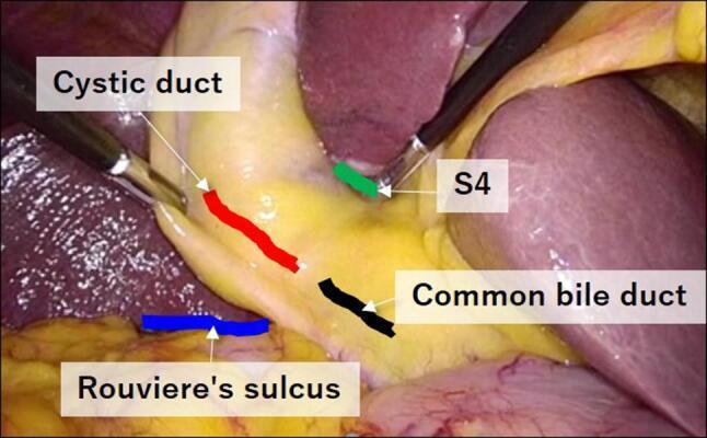
An intraoperative clinical photograph captured during a laparoscopic cholecystectomy, demonstrating key anatomical landmarks within the hepatocystic triangle (Calot’s triangle). The image shows the surgical field with labeled overlays identifying critical structures: the cystic duct (marked in red), the common bile duct (marked in black), the lower edge of the left medial liver segment or S4 (marked in green), and Rouviere's sulcus (marked in blue). Two laparoscopic graspers are visible, retracting tissue to expose the 'Critical View of Safety.' The cystic duct is shown extending from the gallbladder neck toward the common bile duct, while Rouviere’s sulcus appears as a distinct horizontal cleft on the liver surface, serving as an essential extrabiliary landmark to identify the plane of the common bile duct and prevent bile duct injury. The visual illustrates the spatial relationships necessary for safe dissection, particularly the orientation of S4 superior to the biliary structures and the horizontal alignment of the sulcus relative to the ductal anatomy.
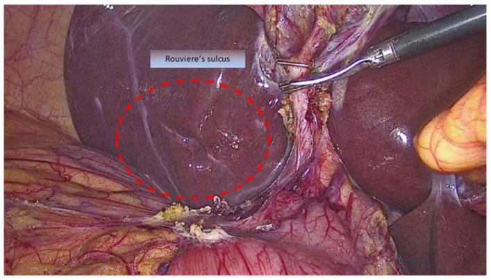
This clinical photograph provides an intraoperative view during a laparoscopic cholecystectomy, focusing on the identification of Rouviere's sulcus (RS). The sulcus is circumscribed by a red dotted line and appears as a horizontal-to-oblique groove approximately 2–5 cm in length on the visceral surface of the liver, specifically in the right lobe lateral to the hepatic hilum. The image demonstrates the anatomical landmark's importance in establishing a 'safe zone' for dissection to avoid bile duct injury. Visible components include the smooth, dark reddish-brown liver parenchyma, surgical grasping instruments retracting the gallbladder neck, and the hepatoduodenal ligament containing critical vascular and biliary structures. The RS serves as a key external landmark indicating the plane of the common bile duct, where dissection superior to this horizontal plane is considered safe. This visual is intended for surgical education regarding the R4U line concept and safe laparoscopic techniques.
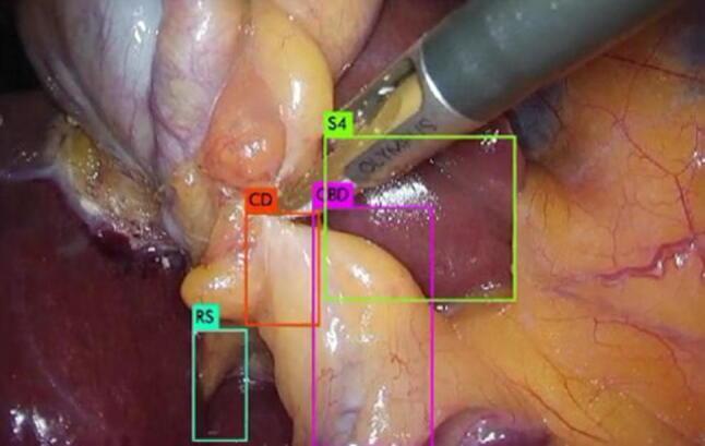
This endoscopic clinical photograph depicts a laparoscopic cholecystectomy, focusing on the hepatocystic triangle (Calot's triangle). The image features four key anatomical landmarks identified by artificial intelligence bounding boxes for surgical navigation: the cystic duct (CD), common bile duct (CBD), the lower edge of the left medial liver segment (S4), and Rouviere’s sulcus (RS). The cystic duct is shown as a pale, tubular structure centrally located, while the common bile duct lies adjacent to it. Rouviere’s sulcus is visible as a distinct fissure in the liver parenchyma, serving as an important extrabiliary landmark to identify the plane of the common bile duct. The image demonstrates the 'Critical View of Safety' technique, aimed at preventing bile duct injuries by clearly identifying these structures before clipping or cutting. A laparoscopic instrument is positioned superiorly near segment 4 of the liver. This visual is designed for surgical training in hepatobiliary surgery and the application of deep learning algorithms in computer-assisted surgery.
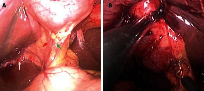
This comparison chart consists of two side-by-side intraoperative laparoscopic photographs (A and B) demonstrating clinical findings during single-incision laparoscopic surgery (SILS) cholecystectomy. View A shows a patient without inflammation, where the peritoneum is thin and transparent. Anatomical landmarks within Calot's triangle are clearly visible before dissection: the cystic artery (red arrow), the cystic duct (green arrow), and Rouviere's sulcus (white arrow). View B depicts a patient with acute cholecystitis, characterized by significant inflammation. The peritoneum is thickened, opaque, and hyperemic, obscuring the underlying anatomy and making the cystic artery and duct difficult to identify. The image illustrates the surgical challenge of achieving the 'critical view of safety' in the presence of acute inflammatory changes, such as edema and tissue friability. This visual aid is intended for surgical education, highlighting the difference between elective biliary anatomy and the pathological distortion encountered in acute hepatobiliary conditions.
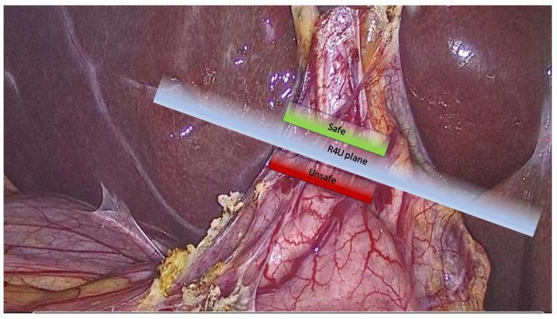
This clinical photograph displays a laparoscopic view of the liver and hepatobiliary region during a surgical procedure, likely a cholecystectomy. An educational overlay illustrates the 'R4U plane,' a conceptual safety boundary used for intraoperative orientation. The R4U plane is depicted as a diagonal, translucent blue transversal plane passing through the level of Rouviere’s sulcus. This plane serves to demarcate 'Safe' vs. 'Unsafe' zones for surgical dissection to prevent iatrogenic bile duct injury. The area cranial (above) to the blue plane is highlighted in green and labeled 'Safe,' indicating where dissection is posterior to the common bile duct plane. The area caudal (below) the plane is highlighted in red and labeled 'Unsafe,' identifying the region containing critical structures like the common bile duct and major vascular pedicles. The image demonstrates the liver parenchyma, cystic pedicle area, and surrounding fatty subserosal tissues, emphasizing the application of cognitive maps in hepatobiliary surgery.
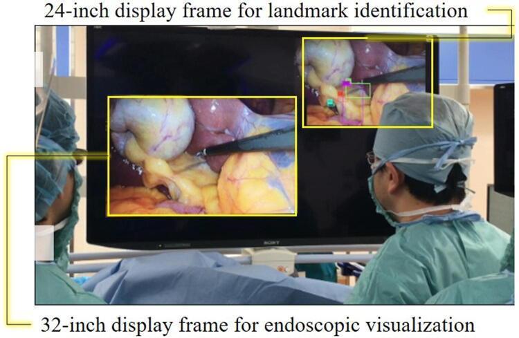
This clinical photograph illustrates a prototype computer-aided surgical navigation system during a laparoscopic cholecystectomy. The image shows a large 8K monitor being viewed by surgical staff in an operating room setting. The display is divided into two primary functional frames: a larger '32-inch display frame for endoscopic visualization' in the lower-left, showing real-time intraoperative footage of Calot's triangle and the gallbladder, and a smaller '24-inch display frame for landmark identification' in the upper-right. The secondary frame utilizes deep learning algorithms (YOLOv3) to overlay colored bounding boxes on specific anatomical landmarks, including the cystic duct, common bile duct, Rouviere’s sulcus, and the lower edge of the left medial liver segment (S4). This setup is designed to assist the surgeon in achieving the 'critical view of safety' by highlighting key biliary and vascular structures to prevent bile duct injuries. The arrangement demonstrates how artificial intelligence can be integrated into the surgical workflow without obstructing the primary operative view.
Rouviere sulcus R4U line laparoscopic cholecystectomy anatomy safety
Rouviere's Sulcus and the R4U Line
What is Rouviere's Sulcus?
Key anatomical facts:
- It is present in approximately 70-82% of patients (absent in ~10-15%)
- It runs between the right lobe anteriorly and the caudate process posteriorly
- It lies at or above the level of the common bile duct (CBD)
- Best visualised laparoscopically when the gallbladder fundus is retracted toward the left shoulder (flipped over)
Why it Matters
- Cystic duct + cystic artery lie ventral and anterosuperior to the sulcus
- Common bile duct (CBD) lies below/posterior to the sulcus plane
- Therefore, dissecting above and anterior to RS keeps you safely away from the CBD
What is the R4U Line?
"The advantage of identifying Rouvière's sulcus and the line joining the roof of the sulcus to the base of segment IV (R4U line) is that the cystic duct and the cystic artery lie ventral (anterosuperior) to the line and the CBD lies below the line. CBD injury can be minimised by maintaining the dissection ventral to the line during cholecystectomy."
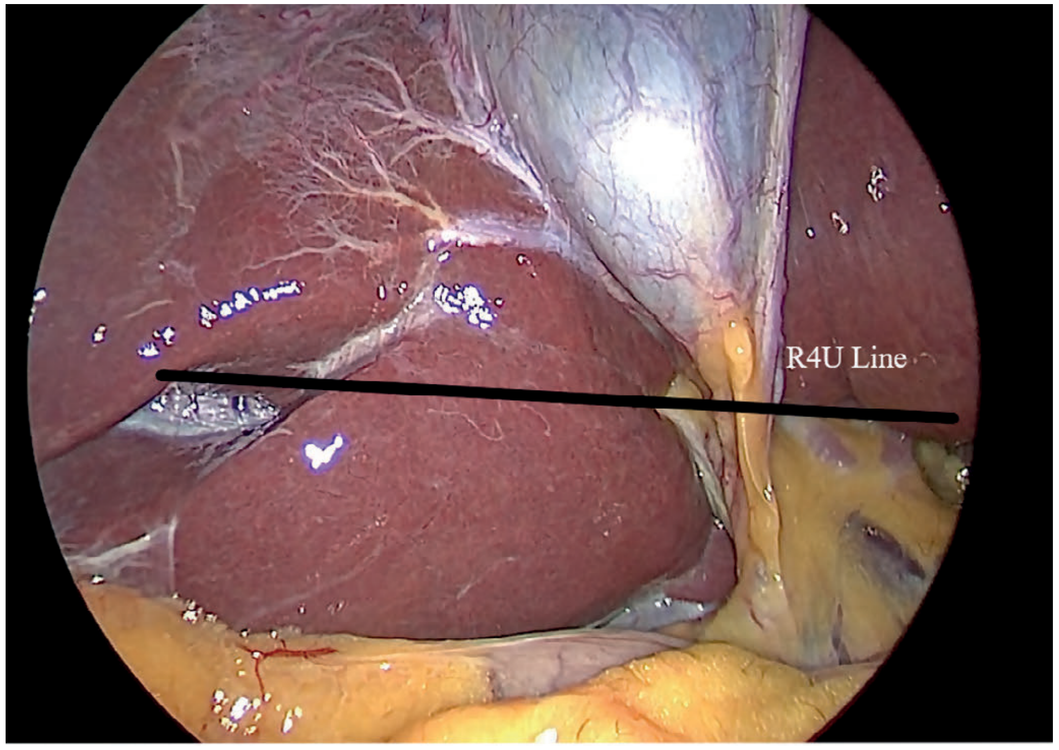
The Safe vs. Unsafe Zones
| Zone | Location relative to R4U line | Structures | Safety |
|---|---|---|---|
| Anterosuperior | Above + anterior to line | Cystic duct, cystic artery | SAFE |
| Posterosuperior | Above but posterior to line | Potentially unsafe | Caution |
| Anteroinferior | Below + anterior | CBD, hepatic artery | UNSAFE |
| Posteroinferior | Below + posterior | CBD, portal vein | UNSAFE |
Labeled Intraoperative Anatomy
Practical Surgical Rules
- Identify RS before starting dissection - look for it early, when the anatomy is still undisturbed
- All dissection must remain ventral (anterior) and superior to the R4U line - this is the golden rule
- If RS is absent (congenitally absent or obscured by adhesions in ~15-30% of cases), use the extension of the umbilical fissure toward the hepatic hilum as the lower boundary of safe dissection
- The mnemonic "RANGERS" - Rouviere's At Neck of Gallbladder Eases Recognition of Structures
Summary Diagram Concept
                    Umbilical fissure
                          |
          Segment IV (base) ← ← ← ←
         /                           \
      ←←←←←←   R4U LINE   ←←←←←←←←  Roof of Rouviere's sulcus
         |                           |
    [SAFE ZONE above this line]      |
    Cystic duct + cystic artery      |
    dissection territory             |
         |                           |
    [UNSAFE below this line]         |
    CBD, hepatic artery, portal vein |
What is right posterior sectoral pedicel?
right posterior sectoral pedicle liver segments anatomy portal triad
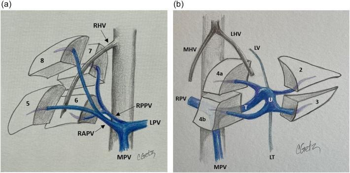
This medical anatomical diagram illustrates the segmental portal venous anatomy of the human liver, divided into two panels. Panel (a) focuses on the Right Portal Vein (RPV) branching from the Main Portal Vein (MPV). It demonstrates the bifurcation of the RPV into the Right Anterior Portal Vein (RAPV), supplying segments 5 and 8, and the Right Posterior Portal Vein (RPPV), supplying segments 6 and 7. The Right Hepatic Vein (RHV) is shown providing a boundary between these segments. Panel (b) illustrates the Left Portal Vein (LPV) anatomy, highlighting its unique structure consisting of a transverse portion (T) and an umbilical portion (U). It depicts the LPV supplying the left-sided segments 2, 3, 4a, and 4b. Key anatomical landmarks related to the LPV are labeled, including the Ligamentum Teres (LT), Ligamentum Venosum (LV), Middle Hepatic Vein (MHV), and Left Hepatic Vein (LHV). The illustration uses color coding (blue for venous, gray for hepatic veins and ligaments) to delineate vascular pathways and their relationships to the functional Couinaud segments of the liver, which are critical for surgical planning and intraoperative ultrasound orientation.
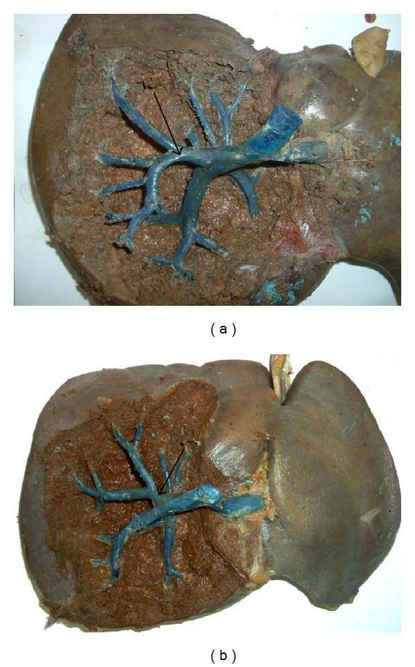
Two clinical photographs (a and b) of gross human liver specimens undergoing anatomical dissection to demonstrate the right sectional pedicles in relation to Rouviere's sulcus. Both images show a partially dissected liver where the smooth Glisson's capsule has been removed to reveal the underlying parenchyma. In image (a), the right posterior sectional pedicle is highlighted, while image (b) shows the right anterior sectional pedicle. In both specimens, the vasculature and biliary structures have been injected with a blue-colored resin or latex to enhance visualization of the branching patterns. The dissections highlight the intrahepatic location of these pedicles within the cleft (sulcus), which serves as an important surgical landmark for identifying the right hepatic pedicle during laparoscopic cholecystectomy or hepatic resection. Black arrows point to specific vascular branching points within the surgical plane. The images illustrate the topographical relationship between the portal triad components and the inferior surface of the liver.
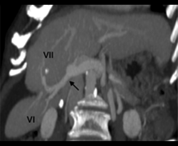
**Imaging Modality:** Computed Tomography (CT), Maximum Intensity Projection (MIP) reconstruction. **Anatomical Region:** Abdomen, specifically focusing on the hepatobiliary system and the right lobe of the liver. **Key Landmarks and Vascular Anatomy:** The image displays the portal venous anatomy within the right hepatic lobe. A prominent right posterior sectorial branch of the portal vein (indicated by a black arrow) is visible, originating from the main portal vein. This branch bifurcates to supply Segment VI (inferiorly) and Segment VII (superiorly). The segmental venules are clearly delineated as they penetrate the hepatic parenchyma. **Observed Pathology/Anatomy:** The image highlights a deep parenchymal cleft or indentation through which the posterior sectorial branch travels. The Couinaud segments VI and VII are labeled, demonstrating the typical distribution of the portal venous supply to the posterior sector of the liver. **Diagnostic Features:** The use of MIP enhancement facilitates the visualization of vascular continuity and branching patterns against the liver parenchyma. This serves as a primary reference for segmental hepatic anatomy and preoperative planning for liver resection or transplant evaluation.
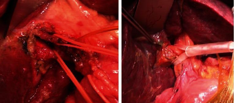
This clinical intraoperative photograph set demonstrates two different surgical techniques for managing the right Glissonean pedicle during liver resection. The left image illustrates the intrafascial approach, characterized by the meticulous dissection and isolation of individual vascular and biliary components within the Glissonean capsule. Several red vessel loops are seen encircling the dissected structures for traction and identification. In contrast, the right image depicts an extrafascial approach or a related step in the cholecystectomy phase, showing a clear catheter inserted into the main bile duct through the cystic duct. The surrounding hepatic parenchyma is visible, with surgical retraction and instruments present at the hilar region. These techniques are critical for selective hepatic inflow vascular control, allowing for precise demarcation of anatomical segments before liver transection. The images are highly relevant for surgical education regarding hepatobiliary anatomy, particularly the various maneuvers used to achieve portal triad control at the hepatic hilum.
right posterior sectoral pedicle liver anatomy segments VI VII portal triad
The Right Posterior Sectoral Pedicle
Definition
The Couinaud Segmental Framework
| Sector | Segments | Blood supply pedicle |
|---|---|---|
| Right anterior sector | V (inferior) + VIII (superior) | Right anterior sectoral pedicle |
| Right posterior sector | VI (inferior) + VII (superior) | Right posterior sectoral pedicle |
Components of the Right Posterior Sectoral Pedicle
1. Right Posterior Portal Vein (RPPV)
- Branches off the main right portal vein
- Runs in a nearly horizontal course at the base of segment V/VI
- Bifurcates to supply segment VI (inferiorly) and segment VII (superiorly)
2. Right Posterior Hepatic Artery
- Branch of the right hepatic artery
- Runs through the hilar transverse fissure (also called the fissure of Gunz) alongside the portal branch
- Often runs horizontally within this sulcus region
3. Right Posterior Sectoral Bile Duct
- Drains bile from segments VI and VII
- Follows an almost horizontal course at the base of segments V and VI
- Can often be seen lying within the transverse fissure on the liver's inferior surface
- Joins the right anterior sectoral duct to form the right hepatic duct
Relationship to Rouviere's Sulcus
Rouviere's sulcus on the undersurface of the right lobe of the liver running to the right of the hepatic hilum marks the position of the right posterior sectoral pedicle.
- Bailey and Love's Short Practice of Surgery, 28th ed., p. 1254
           HEPATIC HILUM
                |
         Right Portal Vein
        /                 \
Right Anterior          Right Posterior
Sectoral Pedicle         Sectoral Pedicle
   |      |                 |      |
  Seg V  Seg VIII          Seg VI  Seg VII
(inferior)(superior)     (inferior)(superior)
                              |
                    Runs HORIZONTALLY at
                    base of segments V & VI
                              |
                    Creates / marks
                    ROUVIÈRE'S SULCUS
                    on visceral liver surface
Why the Right Posterior Pedicle Has a Unique Course
- It creates the visible transverse groove = Rouviere's sulcus
- Its bile duct component is the right posterior sectoral duct, which also runs horizontally - making it particularly vulnerable to injury if dissection strays below the R4U line
- It has a relatively short extrahepatic course, entering the liver parenchyma quickly after branching from the main right portal structures
Surgical Importance
| Situation | Relevance of right posterior sectoral pedicle |
|---|---|
| Laparoscopic cholecystectomy | Rouviere's sulcus marks its position; dissection must stay anterior/superior to avoid injuring its structures |
| Right posterior sectionectomy | This pedicle is the inflow target for selective clamping before segment VI/VII resection |
| Extended left hepatectomy | Transection plane passes anterior to this pedicle |
| Bile duct injury risk | The horizontal right posterior sectoral duct is particularly prone to mistaken clipping during difficult cholecystectomy |
What does nucleation means? I'm talking about the risk factor for gallbladder.
nucleation gallstone formation bile cholesterol crystal risk factor pathophysiology
cholesterol gallstone nucleation crystal formation bile supersaturation diagram
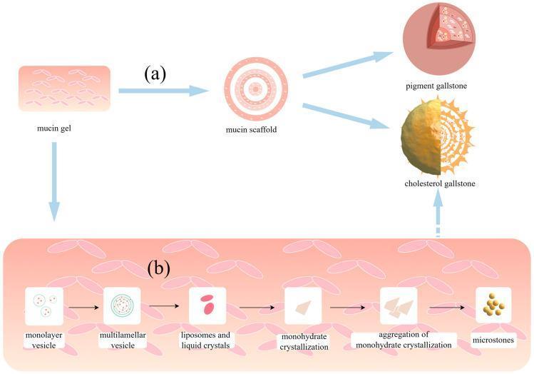
A medical pathophysiology diagram illustrating the mechanisms of gallstone formation mediated by mucin. Section (a) shows the progression from a highly viscous mucin gel to a structured mucin scaffold, which serves as a matrix for the development of both pigment gallstones and cholesterol gallstones. Section (b) details the step-by-step nucleation and growth pathway of cholesterol gallstones within the mucin environment. The process begins with monolayer vesicles transitioning into multilamellar vesicles, which then fuse into liposomes and liquid crystals. This leads to monohydrate crystallization, followed by the aggregation of these crystals to form microstones. These microstones eventually mature into larger macroliths or cholesterol gallstones. The diagram highlights the role of mucins as essential scaffolds and accelerators for vesicle fusion and crystal nucleation in supersaturated bile. Key medical concepts depicted include biliary lithogenesis, the biochemical transition of cholesterol vesicles, and the structural influence of the mucin network in the gallbladder.

Gross pathology photograph of a cholesterol-rich gallstone in transverse cross-section, illustrating internal architecture and mineralized components. The stone displays a dense, dark central core, presumed to be bilirubin- and pigment-rich, surrounded by radiating spokes of translucent, lipid-rich material and crystallized cholesterol. The central nidus is encased by a broader, brownish to tan periphery composed of cholesterol crystals interlaced with calcific deposits. The core region contains amorphous, pigmented material with mineral admixtures such as calcium carbonate and calcium phosphate, consistent with bilirubinate pigments frequently seen in cholesterol stones. The radiating crystal scaffolding appears as linear, fan-shaped arrays extending toward the stone margin, reflecting nucleation and crystallization processes that progressively organize cholesterol monohydrate crystals. The overall morphology is multilaminar, with zones of variable density and mineral content, indicating concentric accretion during stone growth. This specimen illustrates the pathophysiology of cholesterol stones arising from supersaturation of cholesterol in bile, with nucleation on organic nidus and subsequent crystallization producing a characteristic radiating pattern. Clinically, such stones contribute to biliary obstruction and cholestasis and are a common cause of cholelithiasis; educationally, this image demonstrates composition, microstructure, and diagnostic implications for gastroenterologists and pathologists. This specimen thus serves as a reference for education, diagnosis, and research.
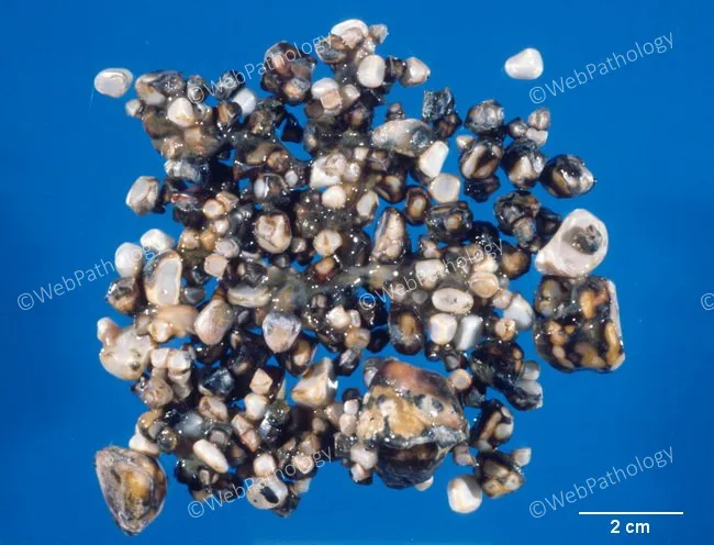
Gross pathology photograph of biliary calculi removed from the gallbladder, illustrating cholesterol-rich stones with mixed composition. The specimen consists of numerous small to medium-sized calculi arranged on a blue background with a 2 cm scale bar for size reference. The stones display a heterogeneous appearance, predominantly pale to tan with varying dark brown to black patches, and surface irregularities consistent with polycrystalline growth. Composition is reported as cholesterol monohydrate crystals interspersed with calcium bilirubinate salts, characteristic of cholesterol gallstones formed in bile supersaturated with cholesterol. Pathophysiologic drivers evident in this context include biliary cholesterol supersaturation, gallbladder hypomotility with bile stasis, nucleation of cholesterol crystals, and mucin overproduction facilitating crystal aggregation. The gross morphology, together with the described crystal content, supports a diagnosis of cholesterol cholelithiasis rather than pigment stone disease. Clinically, such stones can cause biliary colic, cholecystitis, or choledocholithiasis, and they are commonly associated with risk factors such as obesity, female sex, and advanced age. This image is relevant for educational demonstrations of stone composition and gallstone pathogenesis, and it can aid differential diagnosis, surgical planning discussions, and radiologic correlation with ultrasound or computed tomography findings that identify dependent, mixed-density calculi. Preservation and dissemination support teaching and research use.
Nucleation - The Key Risk Factor in Gallstone Formation
What is Nucleation?
"While supersaturation of bile with cholesterol is an important prerequisite for gallstone formation, it is generally not sufficient by itself to produce cholesterol precipitation in vivo. Most individuals with supersaturated bile do not develop stones because the time required for cholesterol crystals to nucleate and grow is longer than the time bile remains in the gallbladder."
- Harrison's Principles of Internal Medicine, 22nd ed.
The 5-Defect Model of Cholesterol Gallstone Formation
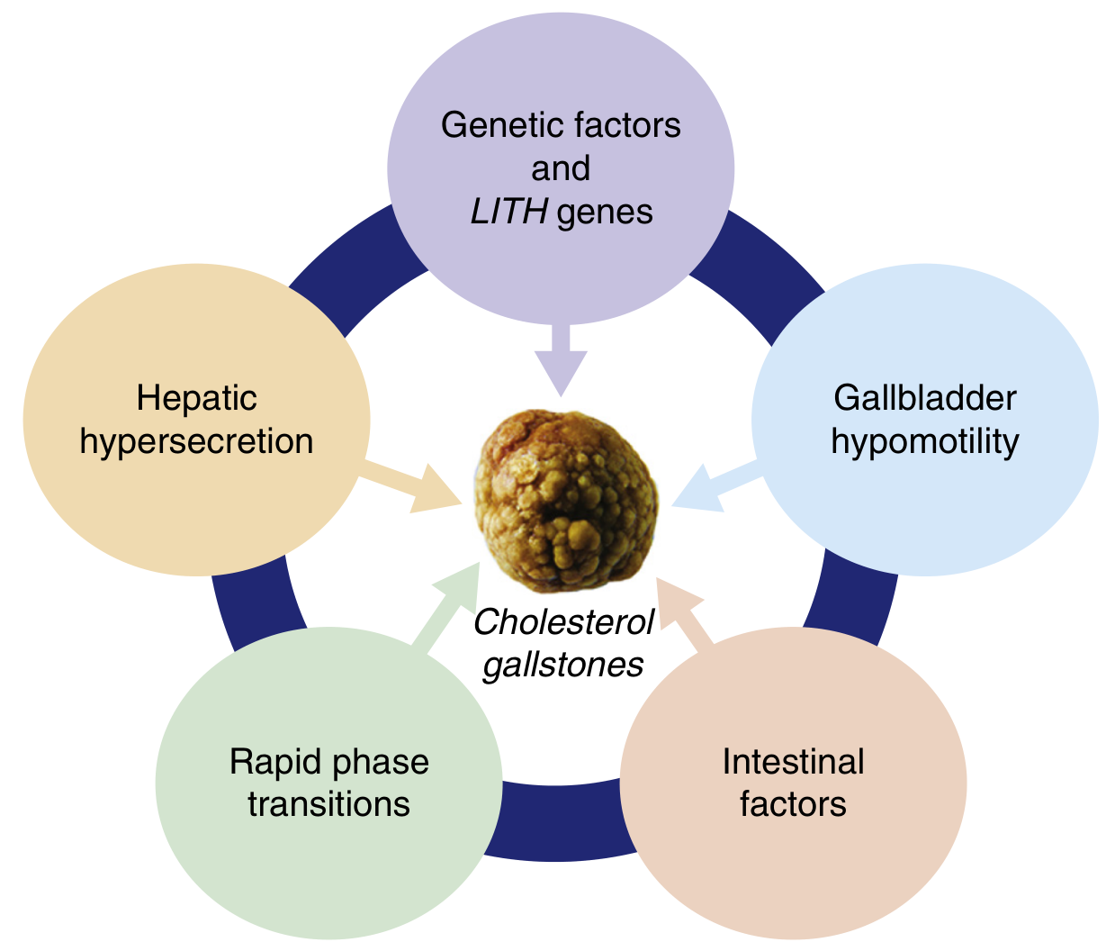
Step-by-Step: How Nucleation Leads to a Gallstone
| Step | What happens |
|---|---|
| 1. Cholesterol supersaturation | Liver secretes excess cholesterol relative to bile salts and phospholipids. Bile becomes "lithogenic." |
| 2. Vesicle formation | Excess cholesterol is carried in unilamellar vesicles (tiny lipid bubbles) in bile |
| 3. Vesicle fusion | Vesicles fuse → multilamellar vesicles → liposomes → liquid crystals |
| 4. NUCLEATION ← | Liquid crystals nucleate into solid cholesterol monohydrate crystals - the point of no return |
| 5. Crystal growth | Crystals grow by drawing more cholesterol from surrounding supersaturated vesicles |
| 6. Aggregation | Crystals clump → microstones |
| 7. Gallstone maturation | Microstones grow into macroscopic gallstones within the mucin gel layer |
Pro-nucleating vs. Anti-nucleating Factors
Pro-nucleating Factors (accelerate crystal formation)
- Mucin glycoproteins - the most important; secreted by gallbladder mucosa; form a gel scaffold where crystals form and grow
- Immunoglobulins (non-mucin glycoproteins)
- Pigment particles - calcium bilirubinate acts as a nucleation seed (relevant in Gilbert's syndrome - UGT1A1 variant)
- Deoxycholate - an expanded deoxycholate bile salt pool enhances cholesterol hypersecretion and nucleation
- Gallbladder hypomotility - stasis increases contact time of bile with mucin gel, greatly promoting nucleation and crystal retention
Anti-nucleating Factors (suppress crystal formation)
- Apolipoprotein A-I
- Apolipoprotein A-II
- Other protective glycoproteins
"Accelerated nucleation of cholesterol monohydrate in bile may be due to either an excess of pronucleating factors or a deficiency of antinucleating factors."
- Harrison's Principles of Internal Medicine, 22nd ed.
Why Gallbladder Hypomotility Makes Nucleation Worse
- Keeps crystals in contact with the mucin gel layer longer
- Allows more cholesterol to deposit on existing crystal seeds
- Is seen in: pregnancy, prolonged fasting, total parenteral nutrition (TPN), octreotide use, rapid weight loss, spinal cord injury
Summary in One Line
What are biradiate and triradiate gall stones
faceted biradiate triradiate gallstones cholesterol multiple stones gallbladder
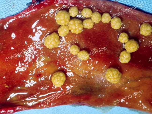
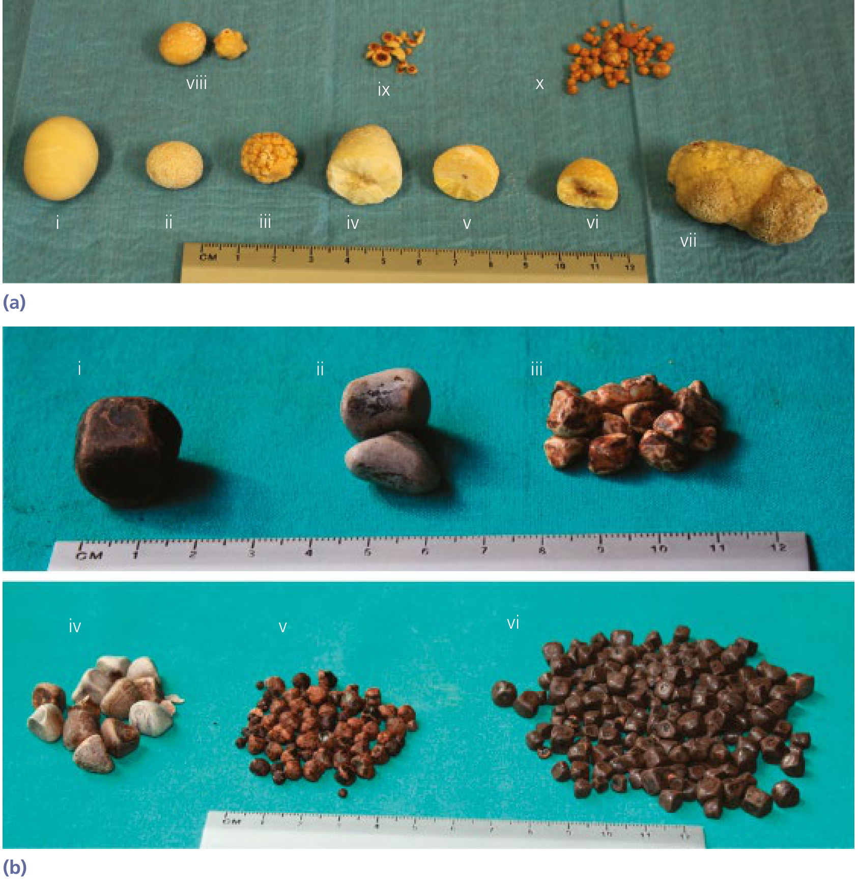
Gross pathology photograph of a gallbladder specimen opened to reveal multiple cholesterol stones. Primary subject: cholesterol gallstones, composed predominantly of cholesterol monohydrate; stones are pale yellow to golden, round to ovoid, variable in size from small to large, with a finely granular, hard exterior surface and a laminated or radiating crystalline interior. Some stones appear faceted due to growth within a confined gallbladder lumen, leading to multi-stone conglomerates that may resemble a cluster of beads. The stones are nonpigmented and not easily crushed between the thumb and index finger, in contrast to pigment stones which are softer and brittle. Exterior surfaces are smooth or slightly pitted; interior structures show crystalline lamellae and directional layering. The gallbladder mucosa may be edematous or mildly inflamed in the surrounding tissue, though the image focuses on the calculi. This gross morphology reflects cholesterol supersaturation of biliary bile, influenced by risk factors such as female sex, obesity, age, and estrogen exposure. Diagnostic significance lies in confirming cholelithiasis with cholesterol composition and helps differentiate from pigment calculus. Clinically, these stones may cause biliary colic, cholecystitis, or pancreatitis and commonly necessitate cholecystectomy. This image is well suited for educational comparison with mixed or pigment stones and for illustrating stone morphology and surgical pathology context.
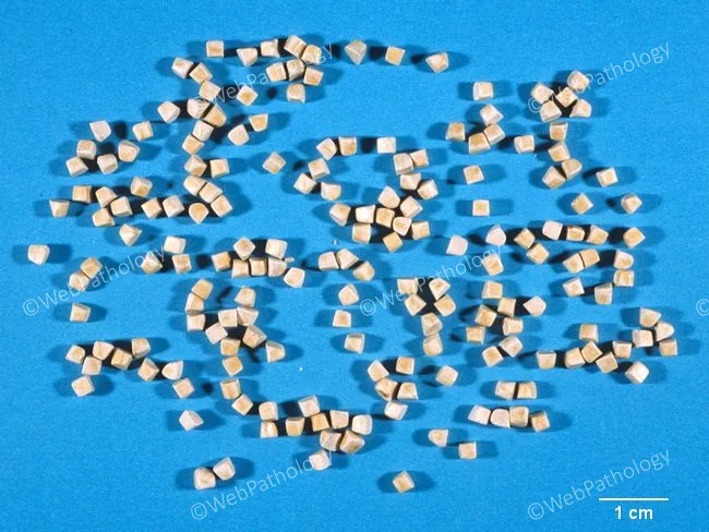
This is a gross pathology photograph illustrating multiple cholesterol gallstones recovered from the gallbladder. The stones are pale yellow to tan, faceted and rounded, arranged across a blue background with a scale bar indicating 1 cm, helping gauge lesion size. The stones appear uniform in size, consistent with a population of cholesterol monohydrate crystals that crystallized and grew concurrently within bile, producing stones of similar diameter. The overall pattern supports cholelithiasis due to cholesterol supersaturation rather than pigment or mixed stones. Their smooth, rounded surfaces suggest a chronic process with gradual calcification; the absence of pigmentation or significant radiodensity implies cholesterol stones are radiolucent on plain imaging, while they may be visible indirectly on computed tomography depending on composition. This image highlights a typical histomorphologic feature: homogeneous cholesterol composition rather than calcium bilirubinate inclusions. Clinically, such stones commonly arise in middle-aged females and individuals with obesity, rapid weight loss, or insulin resistance; they predispose to biliary colic and cholecystitis if obstructive. For educational purposes, this specimen is valuable for teaching stone morphology, size distribution, and the concept of simultaneous crystallization. It can be used in differential diagnosis exercises, radiologic-pathologic correlation discussions, and surgical planning scenarios such as cholecystectomy or gallstone management.
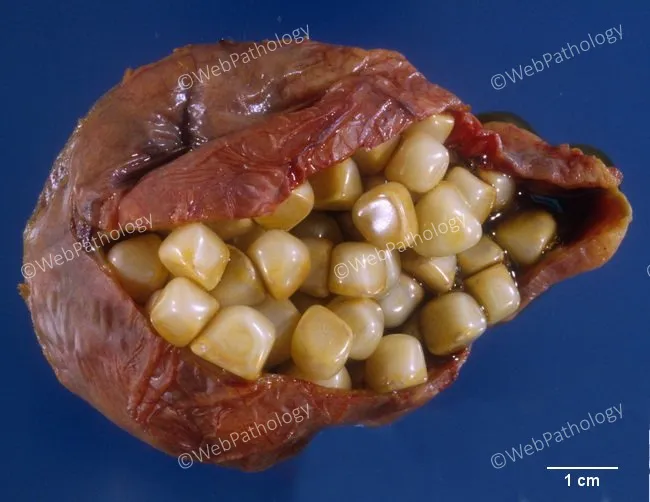
This gross pathology photograph depicts a gallbladder specimen opened to reveal intraluminal cholesterol gallstones. The organ shows a lumen densely packed with pale yellow to tan calculi, ranging from several millimeters to several centimeters in diameter. In some views a single large round stone may occupy the fundus, but more commonly there are multiple round or faceted stones that collectively fill the lumen. Faceting results from tight apposition of stones within the confined gallbladder cavity, creating polygonal, flat surfaces. The stones are cholesterol-type, typically radiolucent on imaging, composed of cholesterol monohydrate crystals with varying amounts of calcium salts, giving a smooth to slightly faceted exterior. The gallbladder wall may appear thinned or mildly contractured due to chronic distension and stone burden, though mucosal details are not always visible in this exterior view. This morphology is classic for cholelithiasis with cholesterol stones; it correlates clinically with biliary colic or chronic cholecystitis and may predispose to obstruction, pancreatitis, or cholangitis if stones migrate. For educational purposes, the image illustrates stone-stone interaction, variable stone sizes, and the spectrum from a solitary large stone to multiple stones occupying the lumen. Scale bar in the image aids size estimation, reinforcing its utility in surgical and teaching settings.
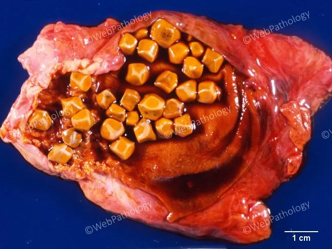
This is a gross pathology photograph of a opened gallbladder specimen displaying multiple yellow-brown cholesterol stones occupying the lumen. The modality is macroscopic pathology, not radiologic imaging, with direct visual assessment of the organ and intraluminal calculi. The primary subject is the gallbladder in the hepatobiliary system, viewed from an anterior/opened perspective to reveal the mucosal surface and stone burden. The stones are cholesterol stones, typically firm, faceted, and pale yellow, measuring several millimeters to over a centimeter in diameter, densely packed within the gallbladder. The gallbladder wall demonstrates acute inflammatory changes, including edema, hyperemia, and surrounding soft-tissue reddening consistent with acute cholecystitis; no bile ducts are visualized in this image. Clinically, such findings correlate with biliary colic symptoms, RUQ or epigastric pain, and vomiting; fever may be absent in uncomplicated cases but can accompany inflammation. The image also underscores Saint’s Triad concepts, with gallstones coexisting with diverticulosis or hiatal hernia in certain populations. Pathologic significance includes confirmation of cholelithiasis with inflammatory gallbladder changes and the consideration of surgical management by cholecystectomy to prevent recurrent attacks or complications such as biliary obstruction. This resource supports education in gross pathology, gallstone disease, and surgical pathology workflows.
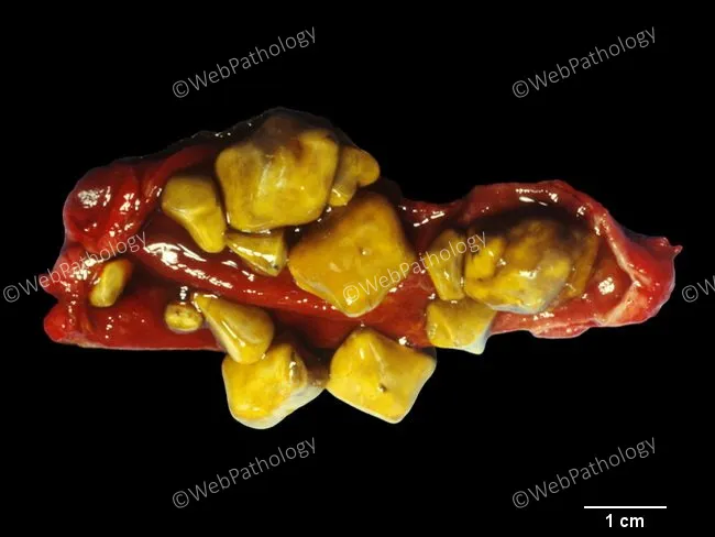
Gross-pathology photograph of gallbladder with cholesterol gallstones. Modality: macroscopic specimen photography under bright-field illumination; scale bar present showing 1 cm for size reference. Location: gallbladder lumen with multiple golden-yellow stones contiguous within a red-brown, flattened gallbladder wall. Stones are irregularly shaped, to molded contours, with smooth, glossy surfaces typical of cholesterol monohydrate composition. Size range spans approximately 2–12 mm for small fragments to larger stones; overall count exceeds a dozen in this specimen. The stones are pale to deep yellow, translucent in appearance, and demonstrate outward molding with faceted edges where they abut the gallbladder mucosa. The surrounding tissue shows minimal inflammatory changes in this specimen, consistent with chronic cholelithiasis without acute cholecystitis. Cholesterol stones arise predominantly in the gallbladder, are the most common calculus type in Western populations, and account for about 75–80% of gallstones. Composition is primarily cholesterol with variable bilirubin content and trace calcium salts. This image highlights a classic presentation: cholelithiasis caused by cholesterol supersaturation of bile; pathogenesis linked to obesity, age, female sex, rapid weight loss, and metabolic syndrome. Clinically, such stones can cause biliary colic, cholecystitis, or pancreatitis if obstructing the cystic or pancreatic duct; definitive management is cholecystectomy. This photograph is suitable for educational, diagnostic, and research contexts.
biradiate triradiate faceted gallstones morphology multiple cholesterol stones
"biradiate" OR "triradiate" gallstone "two stones" "three stones" faceted shape
Mercedes Benz sign gallstone triradiate gas nitrogen plain radiograph
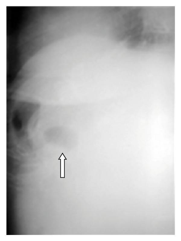
This diagnostic image is a plain abdominal X-ray (radiograph) focusing on the right upper quadrant. The image demonstrates a localized, oval-to-circular radiolucent area (indicated by a white arrow) situated within the anatomical region of the gallbladder. This focal radiolucency is characteristic of pneumobilia or air within the gallbladder (cholecystenteric fistula). The surrounding abdominal area shows general radiopacity, consistent with soft tissue and liver density. The visual finding is a key radiographic sign for diagnosing gallstone ileus, where a cholecystoduodenal fistula has allowed gas from the gastrointestinal tract to enter the biliary system. The primary educational focus is the recognition of abnormal gas patterns (Rigler's triad) in the context of mechanical bowel obstruction caused by a migrated gallstone.
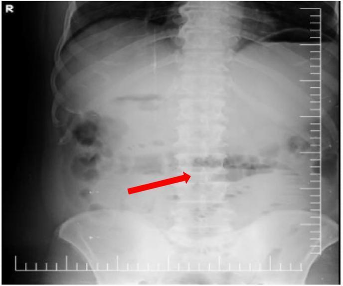
This diagnostic image is an erect anteroposterior (AP) abdominal plain film radiograph. The imaging reveals signs consistent with a small bowel obstruction. Key findings include mildly dilated loops of the small bowel localized primarily in the central abdomen. Multiple horizontal air-fluid levels are visible within these dilated segments, a classic radiographic sign of intestinal stasis or mechanical obstruction. A red arrow specifically highlights one such air-fluid level within a small bowel loop. Additionally, the stomach shows distention with a prominent air collection and an internal fluid level. The overall gaseous distribution is abnormal, with a lack of significant gas in the distal colon or rectum visible in this view. In the clinical context of Rigler's triad, these findings support a diagnosis of gallstone ileus, where a large ectopic gallstone causes mechanical small bowel obstruction. This radiographic study is a primary educational example for medical students and radiology residents to identify bowel dilation and obstructive patterns on plain film imaging.
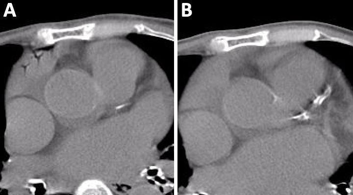
This diagnostic comparison contains two axial non-contrast chest CT scans (Figure 1A and 1B) illustrating an intracardiac air embolism. Figure 1A, an electrocardiography-asynchronized CT, demonstrates the 'Mercedes-Benz sign' in the right atrium. This sign is characterized by linear, low-attenuation (dark) gas collections within the atrial lumen, branching into a configuration reminiscent of the Mercedes-Benz logo. The appearance is a dynamic artifact caused by the movement of air during the cardiac cycle in a non-synchronized acquisition. Figure 1B shows a follow-up CT of the same anatomical region taken two days later, which reveals complete resolution of the intracardiac air, with the right atrium now exhibiting homogeneous soft-tissue density. This clinical comparison is used to teach the recognition of venous air embolisms, which can occur as a complication of peripheral venipuncture, and highlights the importance of imaging timing and technique in detecting transient gas within cardiac chambers.
Biradiate and Triradiate Gallstones
The Core Concept: Why Fissures Form
| Fissure pattern | Appearance | Sign name | Seen when... |
|---|---|---|---|
| Biradiate | 2 radiolucent lines radiating from centre | "Seagull" sign | 2 fissures form |
| Triradiate | 3 radiolucent lines in a Y/star shape | "Mercedes-Benz" sign | 3 fissures form |
The Classic Plain X-Ray Appearance
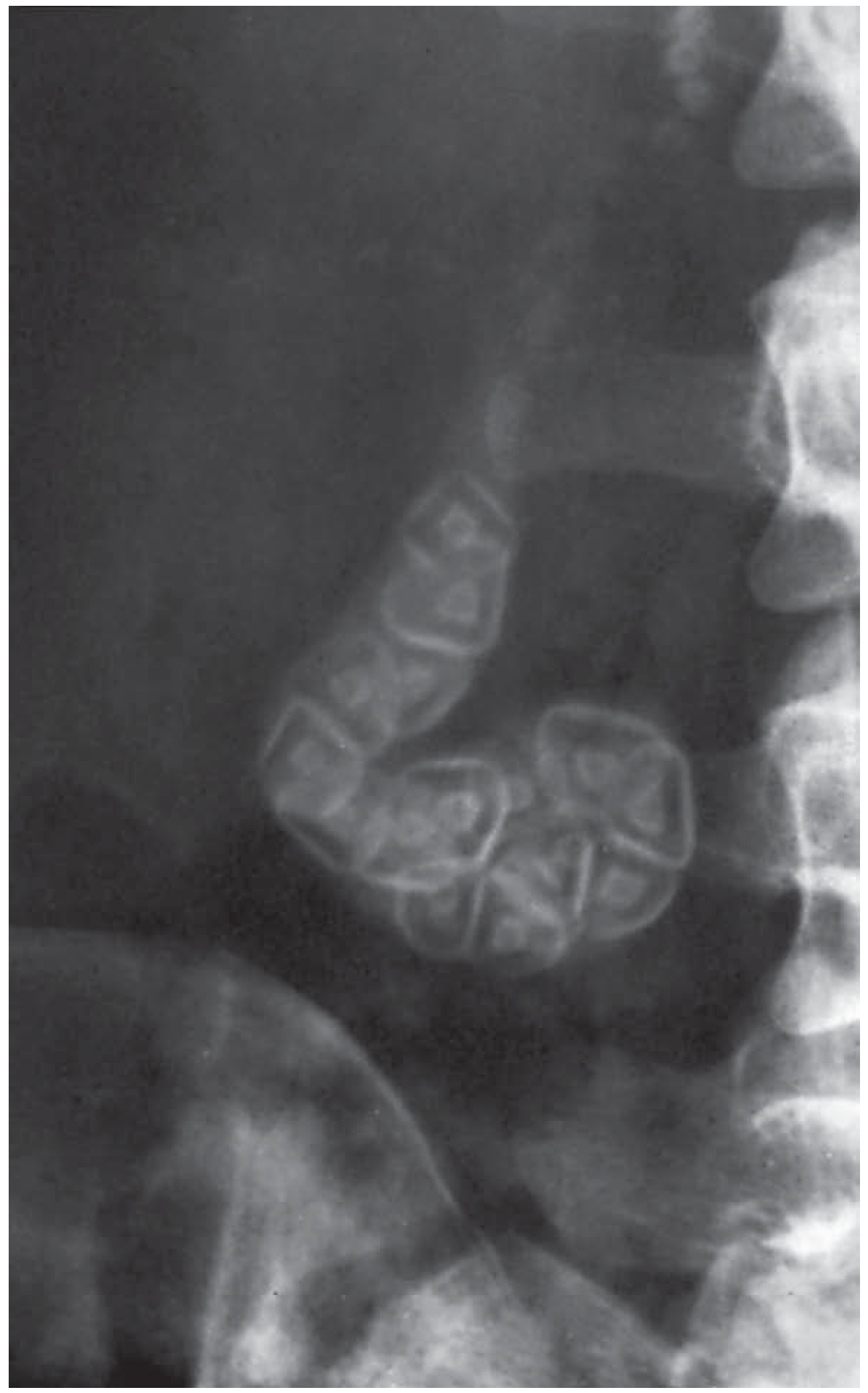
"Plain radiograph showing radio-opaque stones with the centre containing radiolucent gas in a triradiate or biradiate fissure ('Mercedes-Benz' or 'seagull' sign)."
- Bailey and Love's Short Practice of Surgery, 28th ed., Fig. 71.4
Why "Mercedes-Benz"?
        |
       / \        ← 3 radiolucent gas-filled
      /   \           fissures radiating from
     /  ★  \         the stone's centre
    /       \
"Seagull" Sign (Biradiate)
Important Points
- Only ~10% of gallstones are radio-opaque on plain films (those with sufficient calcium content) - the biradiate/triradiate sign is only seen in these calcified stones
- The gas is nitrogen, released from decomposing cholesterol crystals - not air swallowed or gas from infection
- The fissures are radiolucent (dark on X-ray) because gas absorbs fewer X-rays than calcium
- These signs are of purely diagnostic/radiological interest - they do not indicate a different clinical severity
- The sign confirms the lesion is a gallstone (rather than a calcified lymph node or other RUQ calcification), because the internal stellate lucency is characteristic of this process
Gallstone Morphology at a Glance