
Anatomy & Physiology: Describe in detail the anatomy of the thoracic cage
thoracic cage anatomy diagram ribs sternum vertebrae
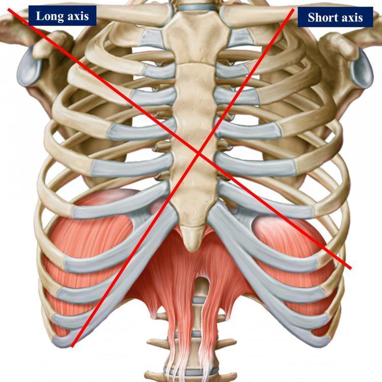
This anatomical diagram provides an anterior view of the human thoracic cage and upper abdominal musculature. The skeletal framework consists of the sternum (manubrium, body, and xiphoid process), articulating ribs with prominent costal cartilages, and components of the shoulder girdle, including the clavicles and glenoid cavities. Two intersecting red lines represent the long and short axes used for cardiac surface projection and surgical landmarks: the 'Long axis' extends from the right shoulder toward the left epigastrium, and the 'Short axis' extends from the left mid-clavicular region toward the right chondrocostal ramp. Inferiorly, the muscular diaphragm is depicted with its dome-like morphology and central tendon, alongside the superior attachments of the rectus abdominis muscle. The diagram serves as a clinical reference for surface anatomy, illustrating the spatial relationships between the thoracic wall and the underlying mediastinal structures, specifically for identifying cardiac chambers and valve locations in medical and osteopathic education.
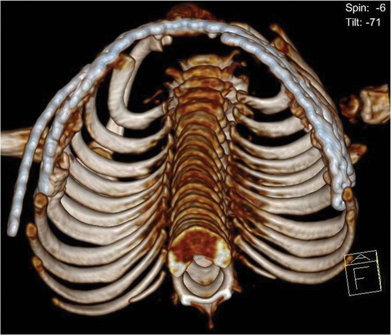
This diagnostic image is a 3D reconstructed CT scan of a pediatric thorax, shown in an axial/oblique superior view. The reconstruction highlights the skeletal anatomy of the thoracic cage, including the ribs, thoracic vertebrae, and sternum. A key clinical feature is the presence of surgical hardware: a long, contoured metallic locking plate is positioned along the anterolateral aspect of the rib cage. The plate is shaped to follow the physiological curvature of the chest wall, bridging multiple ribs to provide structural stability and restore thoracic volume. This intervention is characteristic of surgical management for Thoracic Insufficiency Syndrome (TIS) associated with restrictive chest wall deformities like Jeune syndrome (asphyxiating thoracic dystrophy). The image demonstrates the restoration of the anterolateral contour following rib resection and expansion thoracoplasty, aimed at increasing pulmonary capacity. Distinctive features include the visualization of the vertebral column and the symmetrical alignment of the ribs secured by the crown-shaped internal fixation device.
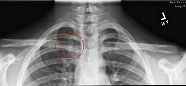
This diagnostic image is an anterior-posterior (AP) X-ray radiograph of the upper thoracic cage, focusing on the pectoral girdle and midline skeletal structures. Visible anatomy includes the cervical and upper thoracic vertebrae, bilateral clavicles, scapulae, and the superior ribs. A red circle highlights the right sternoclavicular joint (SCJ), where the medial end of the right clavicle articulates with the manubrium of the sternum. While the overall bony alignment appears grossly normal in this static view, the highlighted area is marked for clinical evaluation of potential joint instability, such as subluxation or asymmetric widening of the joint space. The radiograph serves as a primary screening tool for orthopedic assessment of the sternoclavicular region in the context of traumatic injury or ligamentous laxity. The lung apices and trachea are also partially visible, providing anatomical context for the thoracic inlet.
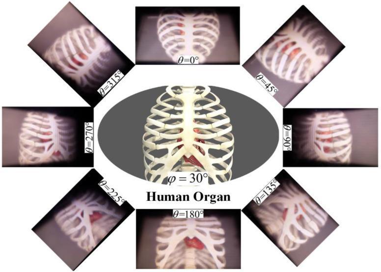
This Comparison Chart illustrates 3D light-field reconstructions of the thoracic cavity for medical diagnosis and education. The central oval image shows a clear, frontal anatomical diagram of the human rib cage and sternum with the heart positioned internally. Surrounding this central figure are eight rectangular frames displaying diagnostic-style 3D renderings of the same structures from different angular perspectives (theta, θ) in 45-degree increments from 0° to 315°. These peripheral images demonstrate the annular viewing capabilities of tabletop light-field displays, showing how the parallax shifts to reveal different facets of the heart and skeletal anatomy. The renderings emphasize depth cues and geometric relationships between the sternum, ribs, and cardiac organ. Some frames exhibit varying levels of clarity, likely to demonstrate the effects of the facet-braiding phenomenon on image quality at specific viewing angles. The content serves as a demonstration of high-fidelity volumetric rendering for biomedical visualization and virtual anatomy training.
sternum anatomy manubrium body xiphoid process
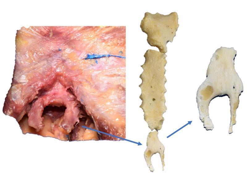
This composite clinical photograph and anatomical display demonstrate an anatomical variation of the sternum: a bifurcated xiphoid process identified during cadaveric dissection. The left panel shows a gross anatomical dissection of the lower thoracic wall, revealing the xiphoid process embedded within muscle fibers and connective tissue. The inferior portion of the xiphoid clearly splits into two distinct, symmetric prongs. The middle and right panels display the isolated, cleaned osseous structures, including the manubrium, sternal body, and the variant xiphoid process. The isolated specimen shows that while the superior half of the xiphoid is unified and articulates with the sternal body, the inferior half is completely bifurcated into two separate bony branches. These branches exhibit roughly equal length and thickness. This variation is clinically significant for surgeons and clinicians performing procedures in the epigastric region or placing chest tubes, as it may impact surface anatomy landmarks or be mistaken for a fracture on diagnostic imaging.
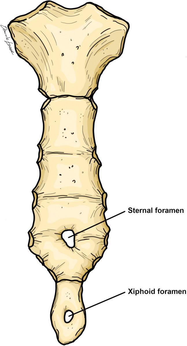
This anatomical diagram illustrates the anterior view of a human sternum, highlighting common congenital variations. The illustration clearly defines the three primary segments: the superior manubrium, the elongated segmented body (gladiolus), and the inferior xiphoid process. Two distinct developmental defects are labeled: a 'Sternal foramen' located in the inferior third of the sternal body and a 'Xiphoid foramen' situated centrally within the xiphoid process. Both foramina are depicted as circular perforations through the bone. These anatomical variants result from the incomplete midline fusion of the cartilaginous sternal bars during embryological development. The image serves as an educational tool for clinical anatomy and radiology, emphasizing the importance of recognizing these benign variants to avoid misinterpretation as pathology (such as lytic lesions) or potential complications during medical procedures like sternal punctures or acupuncture.
rib anatomy structure head neck tubercle costal groove
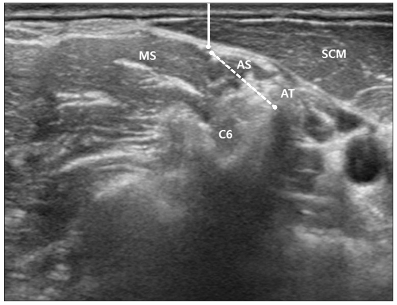
**Imaging Modality:** Ultrasound (B-mode) **Anatomical Region:** Lateral cervical region (neck) at the level of the sixth cervical vertebra (C6). **Key Landmarks and Structures:** * **Musculature:** The sternocleidomastoid muscle (SCM) is visible superficially. The anterior scalene muscle (AS) and middle scalene muscle (MS) are identified in the interscalene groove. * **Neural Structures:** The phrenic nerve is visualized on the superficial surface of the anterior scalene muscle. The C6 nerve root is visible deep to the scalene musculature. * **Bony Landmarks:** The anterior tubercle (AT) of the C6 transverse process is identified as a hyperechoic structure with posterior acoustic shadowing. **Observed Measurements/Features:** * **Phrenic Nerve Depth:** Indicated by a solid vertical line measuring the shortest distance from the skin surface to the phrenic nerve epineurium. * **Anatomical Relationship:** A dotted line illustrates the spatial relationship and distance between the phrenic nerve and the C6 anterior tubercle. **Clinical Context:** This sonogram demonstrates the regional anatomy relevant for ultrasound-guided nerve blocks or phrenic nerve identification, highlighting the nerve’s proximity to the skin surface and cervical landmarks.
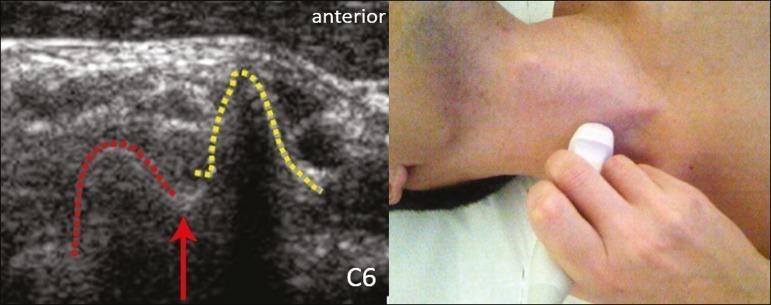
This composite figure features a clinical photograph of a neck ultrasound examination alongside the resulting diagnostic ultrasound image of the C6 cervical nerve root and its related skeletal landmarks. The ultrasound image (left) uses a transverse plane to demonstrate the characteristic morphology of the C6 transverse process. The anterior tubercle is outlined with a yellow dotted line, appearing as a prominent peak-like hyperechoic structure. The posterior tubercle is outlined with a red dotted line, presenting as a rounded hyperechoic prominence. A solid red arrow identifies the C6 nerve root, which appears as a round hypoechoic (dark) structure resting in the groove between the anterior and posterior tubercles (the 'intertubercular sulcus'). This specific anatomical configuration, where the two tubercles are of similar height, is a key diagnostic landmark for identifying the C6 level during regional anesthesia or cervical nerve blocks. The clinical photograph (right) shows the transducer placement on the lateral aspect of the neck to obtain this view.
The Thoracic Cage - Detailed Anatomy
1. Overview and Shape
- Superior thoracic aperture (thoracic inlet): Bounded by the T1 vertebra posteriorly, the medial border of the first rib and its costal cartilage laterally, and the upper border of the manubrium anteriorly. It transmits the trachea, oesophagus, large vessels, and nerves.
- Inferior thoracic aperture (thoracic outlet): Bounded by T12 posteriorly, the 11th and 12th ribs laterally, the costal margin (formed by the costal cartilages of ribs 7-10) anterolaterally, and the xiphisternal junction anteriorly. It is closed by the diaphragm.
2. The Sternum
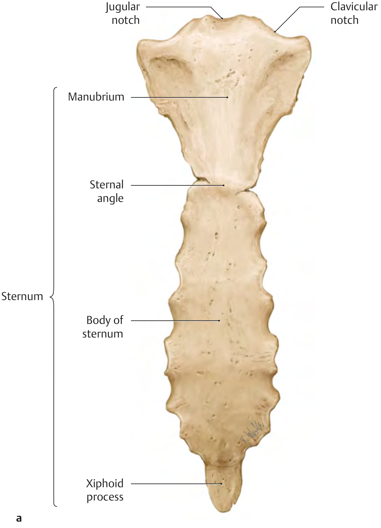
Manubrium
- The widest and thickest part, roughly quadrilateral in shape.
- Its superior border bears the jugular (suprasternal) notch in the midline, flanked on each side by a clavicular notch for articulation with the medial end of the clavicle (sternoclavicular joint).
- Just below each clavicular notch is the first costal notch, where the first rib forms a synchondrosis (not a true synovial joint).
- The inferolateral border bears a facet for the upper half of the 2nd costal cartilage.
Sternal Angle (Angle of Louis)
- The manubrium meets the body at a slightly backward angle, forming the palpable sternal angle (manubriosternal joint / Louis' angle) at the level of T4-T5.
- The 2nd costal cartilage articulates here - making the sternal angle the key clinical landmark for counting ribs.
- The manubriosternal joint is a secondary cartilaginous joint (symphysis) that ossifies with age.
Body of the Sternum (Gladiolus)
- Longer and narrower than the manubrium.
- Its lateral borders bear costal notches for the 2nd through 7th costal cartilages (the upper notch is shared with the manubrium for the 2nd rib).
- Costal notches for the 6th and 7th cartilages are placed very close together near the inferior end.
Xiphoid Process
- The smallest and most inferior part; variable in shape and sometimes bifid or perforated (a benign variant).
- Frequently remains cartilaginous well into adulthood.
- Has no costal attachments but gives origin to some abdominal muscles and ligaments.
- The xiphisternal joint ossifies with age.
3. The Ribs
| Class | Ribs | Anterior Attachment |
|---|---|---|
| True (vertebrosternal) ribs | 1-7 | Direct attachment to sternum via costal cartilage |
| False (vertebrochondral) ribs | 8-10 | Costal cartilage joins the cartilage of the rib above |
| Floating (vertebral) ribs | 11-12 | No anterior bony or cartilaginous attachment |
Structure of a Typical Rib (Ribs 3-9)
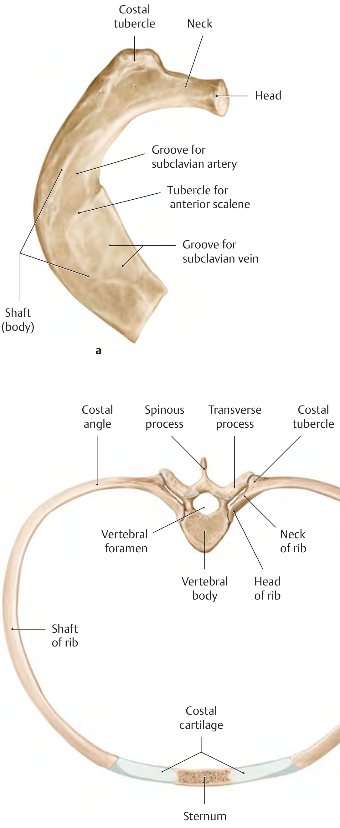
- Head - bears two articular facets (demifacets) separated by the crest of the head; these articulate with the costal facets on the bodies of two adjacent thoracic vertebrae (e.g., rib 6 articulates with T5 and T6).
- Neck - a flattened segment connecting the head to the tubercle; bears a sharp crest of the neck on its superior border (except rib 1).
- Costal tubercle - a roughened elevation at the junction of the neck and shaft. It has an articular facet for the costal facet on the transverse process of the corresponding vertebra (costotransverse joint), and a non-articular part for ligament attachment.
- Shaft (body) - the longest segment; it curves forward and at the costal angle (the most posterior point of the rib) twists slightly so the external surface faces somewhat downward at the vertebral end and upward anteriorly.
- Costal groove - a groove along the inferior inner border of the shaft (present on ribs 2-10 except 11 and 12) that protects the intercostal nerve, artery, and vein (from above downward: vein, artery, nerve - VAN).
Atypical Ribs
- Rib 1: Shortest and most curved. Flat (upper and lower surfaces instead of inner and outer). Has a scalene tubercle on its upper surface for the anterior scalene muscle, with a groove for the subclavian vein anterior to it and a groove for the subclavian artery posterior to it. Its head has only one articular facet (articulates only with T1). No costal groove.
- Rib 2: Longer than rib 1; has a roughened area on its outer surface (tuberosity for serratus anterior).
- Ribs 11 & 12: Have a single facet on the head (articulating with their own vertebra only), no neck or tubercle, and no costotransverse joint. They are short and have no anterior connection. No costal groove on rib 12.
4. Costal Cartilages
5. Joints of the Thoracic Cage
Costovertebral Joints (Posterior)
- Between the head of the rib and the costal facets (demifacets) on the bodies of adjacent vertebrae.
- Ribs 1, 10, 11, and 12 each articulate with only one vertebral body.
- Ribs 2-9 articulate with two adjacent vertebrae (the head straddles the intervertebral disc).
- A fibrocartilaginous intra-articular ligament divides the joint space into two compartments in most ribs.
- Reinforced by the radiate (stellate) ligament anteriorly.
- Between the articular facet on the costal tubercle and the costal facet on the transverse process of the corresponding vertebra.
- Present only for ribs 1-10 (ribs 11 and 12 lack transverse process facets and have no costotransverse joint).
- Stabilized by three ligaments:
- Lateral costotransverse ligament - from the tip of the transverse process to the costal tubercle
- Costotransverse ligament - between the neck of the rib and the transverse process
- Superior costotransverse ligament - between the neck and the transverse process of the vertebra above
Sternocostal (Sternocostal) Joints (Anterior)
- The 1st sternocostal joint is a synchondrosis (no synovial cavity); the cartilage fuses directly with the manubrium.
- The 2nd through 7th joints are synovial plane joints, reinforced by radiate sternocostal ligaments anteriorly and posteriorly, and by the intra-articular sternocostal ligament within the joint.
- The manubriosternal and xiphisternal joints are secondary cartilaginous joints (symphyses) that progressively ossify.
Interchondral Joints
- Small synovial joints between adjacent costal cartilages (6th-7th, 7th-8th, 8th-9th, and occasionally 9th-10th), reinforcing the costal margin.
6. Thoracic Vertebrae
- Costal facets (demifacets) on the bodies: superior and inferior articular facets for the heads of ribs. Vertebrae T1 and T10-T12 have complete facets; T2-T9 share demifacets between adjacent vertebrae.
- Costal facets on transverse processes (present on T1-T10): for the costal tubercles.
- Long, downward-sloping spinous processes - they overlap each other (especially T5-T8), limiting extension.
- Heart-shaped vertebral bodies in cross-section; bodies increase in size from T1 to T12 (weight-bearing).
- Circular vertebral foramen.
7. Movements of the Thoracic Cage
- Upper ribs (1-6): The axis of rotation runs roughly in the coronal plane. When elevated during inspiration, they push the sternum anteriorly - increasing the anteroposterior (sagittal) diameter ("pump-handle" motion).
- Lower ribs (7-10): The axis runs more in the sagittal plane. Elevation increases the transverse diameter of the lower thorax ("bucket-handle" motion).
- Rib 11 & 12: Act like "callipers," moving outward to increase the abdominal diameter ("caliper" motion).
8. Clinical Correlations
- Sternal angle of Louis (T4/T5 level): landmark for the 2nd rib, aortic arch, carina of trachea, and azygos vein entry.
- Costal groove position: intercostal neurovascular bundle runs under each rib in the groove - needles and drains are inserted along the upper border of the rib below to avoid these structures.
- Floating ribs (11-12): Can be mistaken for pathological masses on clinical examination.
- Cervical rib: Anomalous rib from C7; can compress subclavian vessels or brachial plexus (thoracic outlet syndrome).
- Pectus excavatum / carinatum: Congenital deformities of the sternum and anterior rib cage.