
Ro plant in dialysis unit Diagram
RO plant reverse osmosis dialysis unit diagram schematic water treatment
A detailed labeled flowchart diagram of a Reverse Osmosis (RO) plant in a hemodialysis unit. Show the complete water treatment process flow from left to right and top to bottom with labeled boxes and arrows. Include these sequential steps clearly labeled: 1) Municipal Tap Water (inlet), 2) Temperature Blending Valve (77°F), 3) Multimedia Depth Filter (removes particulate matter and turbidity), 4) Water Softener (ion exchange resin - removes Ca2+ and Mg2+ ions, prevents membrane scaling), 5) Activated Carbon Tanks x2 (adsorbs chlorine, chloramines, organic substances, endotoxins), 6) 5-micron Cartridge Filter (prevents carbon particles from entering RO pump), 7) High Pressure Pump (15-20 bar pressure), 8) RO Membrane Unit / Double-pass RO (semipermeable membrane, pore size less than 1.0 nm, rejects 90-99% ions, bacteria, endotoxins) - show two outputs: PERMEATE/PRODUCT water (arrow going forward) and REJECT/CONCENTRATE water (arrow going to drain), 9) Optional: Deionization / Mixed Bed Ion Exchange (for heavy ionic contamination), 10) Storage Tank (product water reservoir), 11) Distribution Loop Pump, 12) Distribution Loop to multiple Dialysis Stations (show 4-5 dialysis machines connected to the loop), 13) Return line back to storage tank completing the loop. Add a small box showing water quality standards: TDS less than 10 ppm, bacteria less than 100 CFU/mL, endotoxin less than 0.25 EU/mL. Use blue color scheme, clean medical diagram style, white background, clear arrows showing flow direction.
RO Plant in a Dialysis Unit
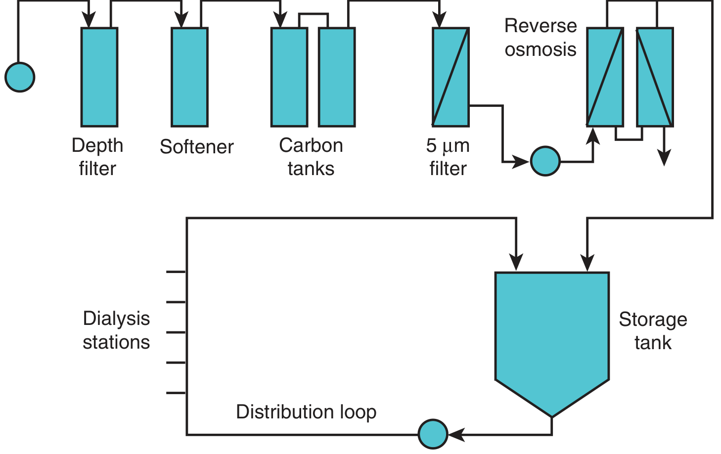
Textbook Diagram (Brenner & Rector's The Kidney)
Detailed Annotated Diagram
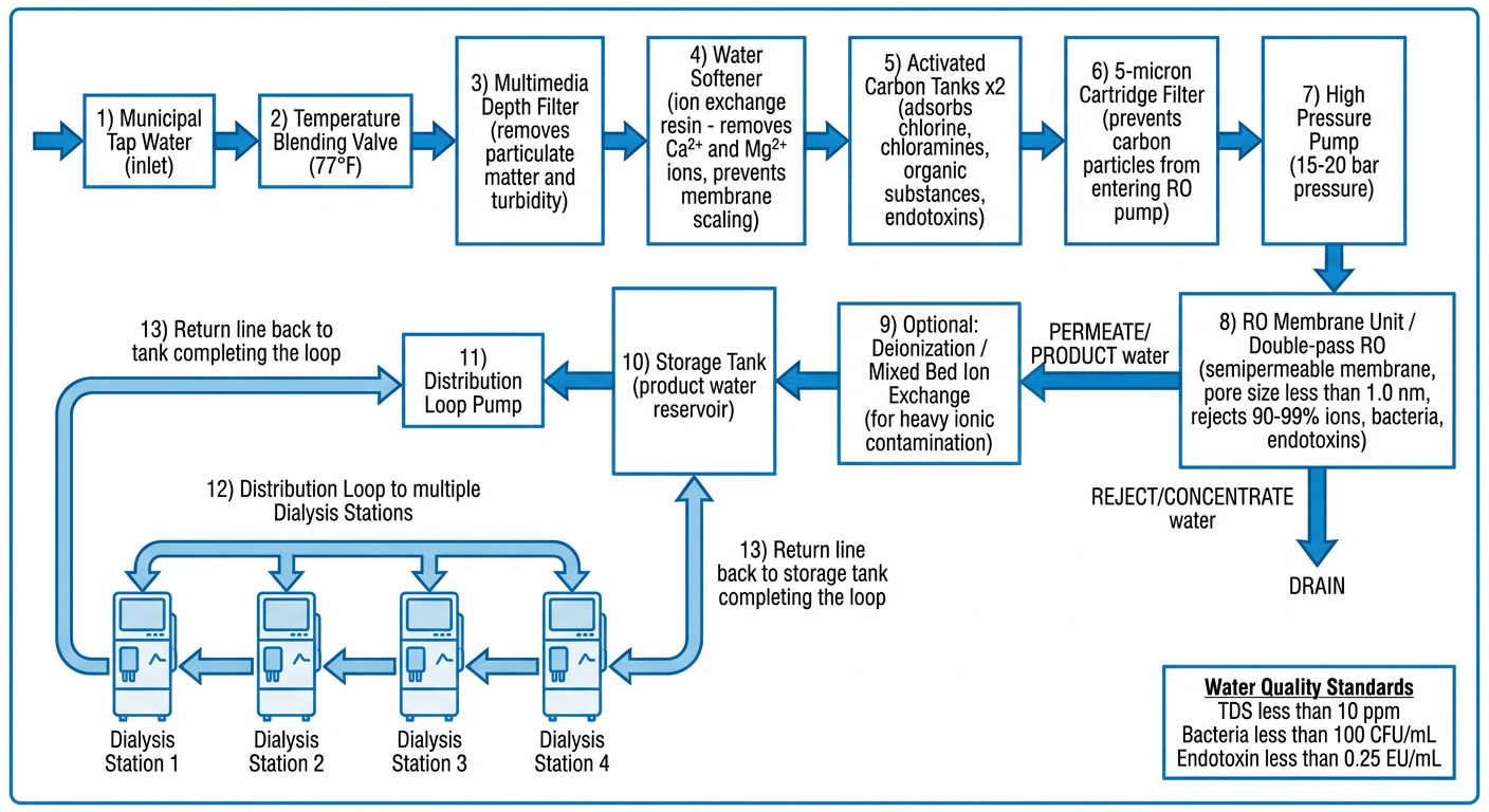
Sequential Stages Explained
| Step | Component | What It Removes / Does |
|---|---|---|
| 1 | Municipal Tap Water | Feed water source |
| 2 | Temperature Blending Valve | Adjusts to ~77°F (25°C); optimal for RO membrane efficiency |
| 3 | Multimedia Depth Filter | Removes particulate matter, turbidity, suspended solids |
| 4 | Water Softener (ion exchange resin, Na⁺ coated) | Removes Ca²⁺, Mg²⁺ and other polyvalent cations - prevents membrane scaling |
| 5 | Activated Carbon Tanks (x2 in series) | Adsorbs chlorine, chloramines, organic substances, endotoxins |
| 6 | 5-μm Cartridge Filter | Prevents carbon particles from fouling the RO pump and membrane |
| 7 | High Pressure Pump | Generates 15-20 bar pressure to drive water through RO membrane |
| 8 | RO Membrane Unit | Pore size <1.0 nm; rejects 90-99% monovalent ions, 95-99% divalent ions, bacteria, endotoxins |
| ↳ Permeate / Product Water (~40-80% of feed) | Purified water - proceeds to storage | |
| ↳ Reject / Concentrate (~20-60% of feed) | Goes to drain | |
| 9 | Deionization (optional) | Mixed-bed ion exchange for areas with heavy ionic contamination |
| 10 | Storage Tank | Buffer reservoir of purified product water |
| 11 | Distribution Loop Pump | Continuously circulates water through the loop |
| 12 | Distribution Loop | Ring main piping to all dialysis stations (600-800 mL/min flow at each station) |
| 13 | Return Line | Unused water returns to storage tank, maintaining continuous flow |
Key Clinical Points
- A standard 4-hour session exposes a patient to 120-160 L of water - contaminants that would be harmless in drinking water become highly dangerous at this exposure
- RO removes aluminum (prevents encephalopathy, bone disease, EPO-resistant anemia)
- Carbon tanks remove chloramines (which cause hemolysis and methemoglobinemia)
- Softener prevents Ca/Mg scaling on RO membranes
- Bacteria: <100 CFU/mL (ultrapure: <0.1 CFU/mL)
- Endotoxin: <0.25 EU/mL (ultrapure: <0.03 EU/mL)
- Aluminum: <0.01 mg/L