3rd 4th 5th 7th nerve anatomy images and 3D images for pg ophthalmology perspective From atlas and kanski khurana
"3b" in /skills/readonly/medical-library/SKILL.md
oculomotor nerve (CN III) anatomy course and nucleus diagram
trochlear nerve (CN IV) anatomy pathway diagram
trigeminal nerve (CN V) anatomy branches ophthalmic division diagram
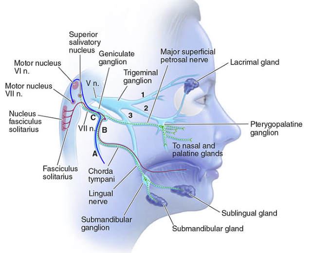
facial nerve (CN VII) anatomy course diagram
oculomotor nerve anatomy diagram
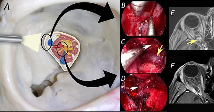
This composite educational image illustrates a transorbital endoscopic-assisted surgical approach for the resection of an orbital apex cavernous hemangioma. Panel A provides a schematic diagram of the orbital apex anatomy, detailing neurovascular structures including the optic nerve, oculomotor nerve branches, and the ophthalmic artery. Panels B, C, and D are intraoperative endoscopic photographs capturing key surgical steps: (B) exposure of the lateral aspect of the superior orbital fissure (indicated by asterisks), (C) identification of the cavernous hemangioma (yellow arrow), and (D) microsurgical dissection of the lesion from the superior division of the oculomotor nerve (white arrow) and the ophthalmic artery (red arrow). Panels E and F present axial T1-weighted MRI scans for comparison: (E) shows the preoperative state with a well-defined mass in the orbital apex compressing adjacent structures, while (F) demonstrates the postoperative result with complete lesion resection and restoration of the orbital apex space. The material is intended for neurosurgical and ophthalmological education, focusing on minimally invasive skull base techniques.
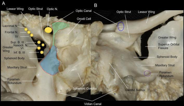
This medical anatomical diagram features two clinical photographs of a dry bone specimen, showing the osseous anatomy of the human orbital apex of the sphenoid bone. Image (A) provides an anterior view, highlighting the optic canal superomedially and the superior orbital fissure (SOF) inferolaterally. Key landmarks include the optic strut, which separates the optic nerve and ophthalmic artery from the SOF contents, and the maxillary strut, which separates the SOF from the foramen rotundum. Overlays illustrate the surgical decompression areas: the light green area denotes the medial wall of the optic canal, and the light blue area indicates the medial wall of the SOF. Image (B) presents a posterior view, showing the spatial relationship between the optic canal, SOF, foramen rotundum, and the carotid sulcus. The diagram identifies neurovascular structures passing through these apertures, including the optic nerve (CN II), oculomotor nerve (CN III), trochlear nerve (CN IV), and divisions of the trigeminal nerve (V1, V2). This resource is designed for advanced surgical planning in endoscopic endonasal decompression procedures.
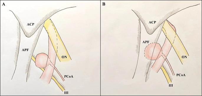
Anatomical comparison diagrams depicting the spatial relationships of the internal carotid artery (ICA) and posterior communicating artery (PCoA) aneurysms from an axial-oblique perspective. Diagram A illustrates a 'regular' PCoA aneurysm, where the aneurysmal neck is positioned at or above the level of the anterior clinoid process (ACP). The ICA shows minimal tortuosity, and the aneurysm is largely visible, lateral to the anterior perforated fossa (APF). Diagram B illustrates a 'low-lying' PCoA aneurysm, characterized by a neck located inferior to the ACP. In this variant, a significant portion of the aneurysm is obscured or 'covered' by the APF (indicated by dashed lines), and there is increased tortuosity between the ophthalmic and communicating segments of the ICA. Key neurovascular structures labeled in both diagrams include the ophthalmic nerve (ON), the oculomotor nerve (III), the ACP, the APF, and the PCoA originating from the ICA. These illustrations demonstrate the surgical anatomy relevant for neurosurgical clipping and the impact of vascular tortuosity on aneurysm location.
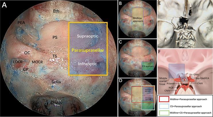
This composite educational graphic illustrates the surgical anatomy and modular corridors of the endoscopic endonasal parasuprasellar approach. Panel A shows an intraoperative endoscopic endonasal view with key landmarks labeled: posterior ethmoidal artery (PEA), planum sphenoidale (PS), optic canal (OC), tuberculum sellae (TS), medial and lateral optocarotid recesses (MOCR, LOCR), carotid protuberance (CP), and the sella. A yellow quadrangle delineates the parasuprasellar area, further divided by the optic nerve into supraoptic and infraoptic regions. Panels B–D provide comparative overlays of different surgical modules: midline (transsellar/transtuberculum), cavernous sinus (CS), and parasuprasellar corridors, coded by color (red, blue, green) to represent various combined surgical approaches. Panel E presents a 3D reconstruction of a postoperative CT scan demonstrating the extent of bone removal. Panel F is a schematic diagram illustrating the neurovascular relationships in the parasuprasellar area, including the optic nerve (CN II), oculomotor nerve (CN III), and supraclinoidal internal carotid artery (ICA). This material is intended for neurosurgical training in skull base surgery and endoscopic corridor selection.
Cranial Nerves III, IV, V, VII — Ophthalmology-Oriented Anatomy with Images
1. Third (Oculomotor) Nerve [CN III]
- Gray's Anatomy for Students, p. 1037, 1083
- Kanski's Clinical Ophthalmology, p. 822
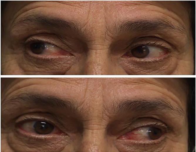
2. Fourth (Trochlear) Nerve [CN IV]
- Gray's Anatomy for Students, p. 1084
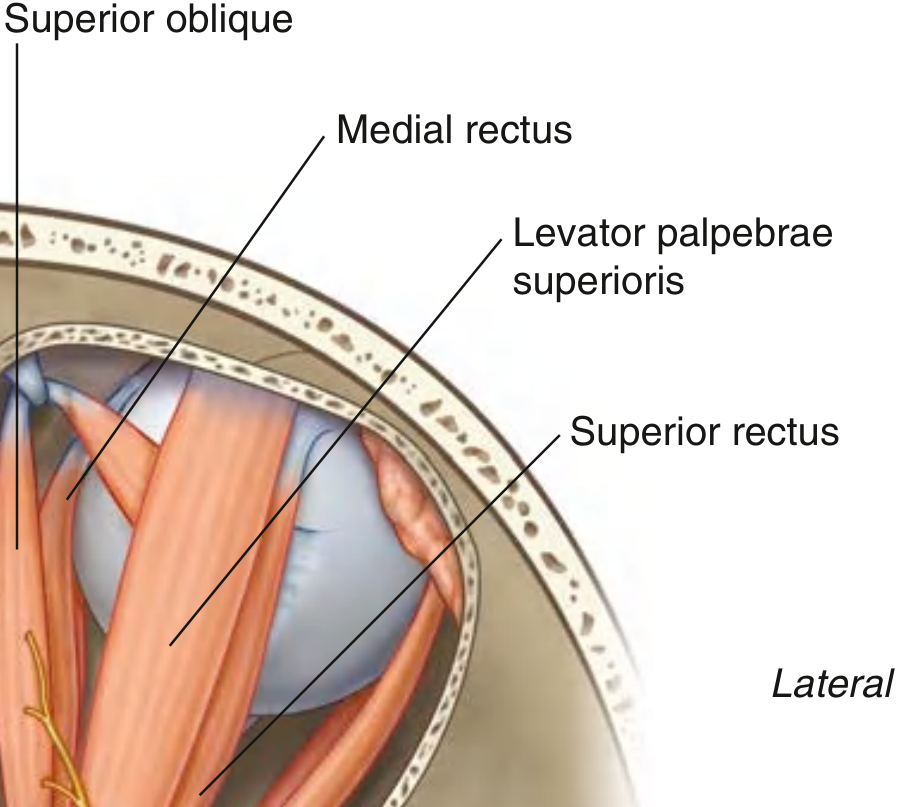
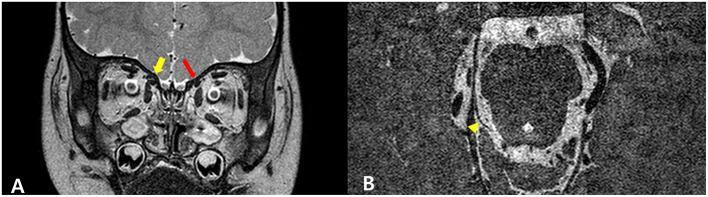
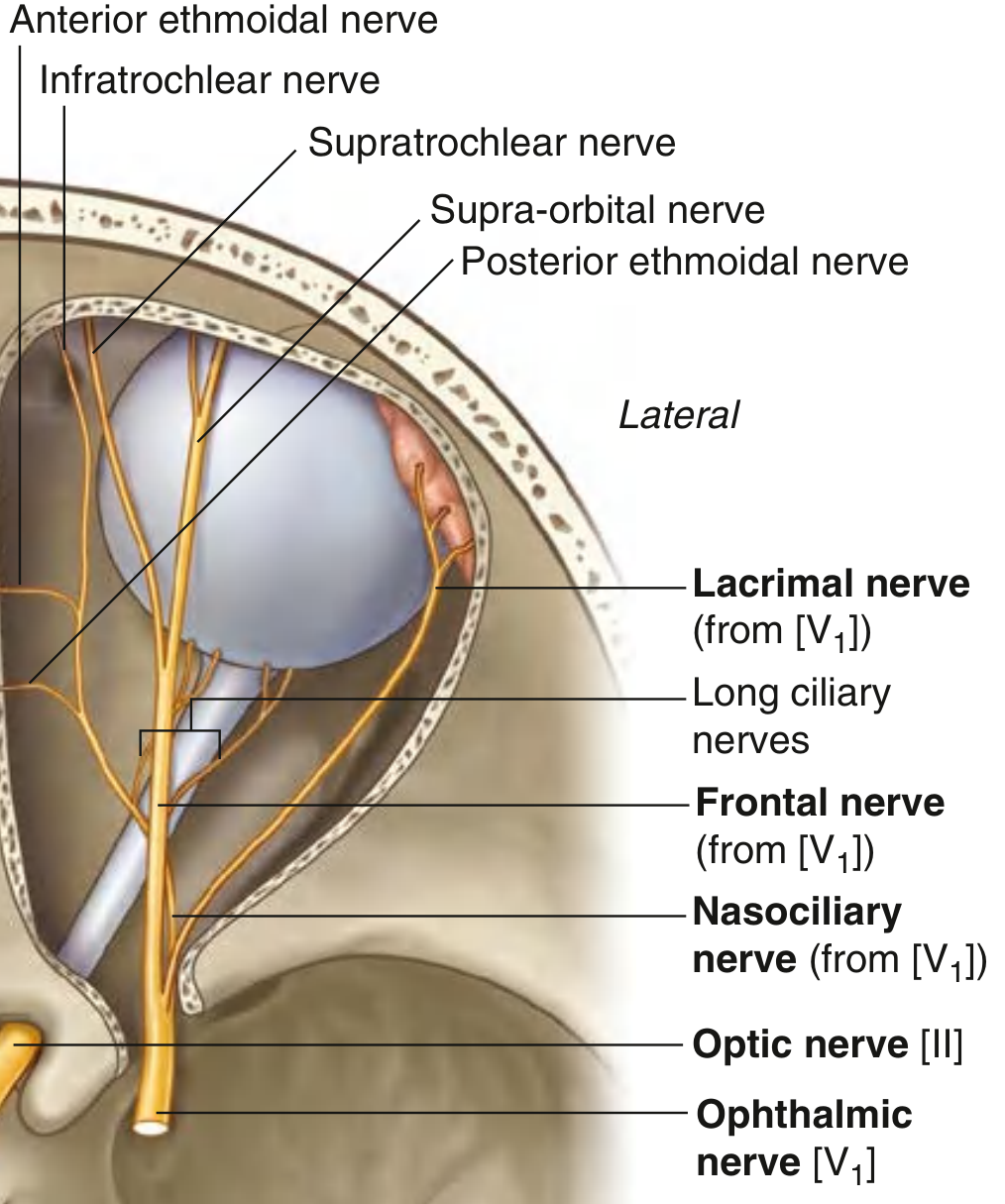
3. Fifth (Trigeminal) Nerve [CN V]
-
V1 (Ophthalmic) - smallest, most superior division, purely sensory. Runs in the lateral wall of the cavernous sinus (below IV and III), enters the orbit via the superior orbital fissure, splitting into lacrimal, frontal, and nasociliary nerves. Supplies the eye, conjunctiva, orbital contents, lacrimal gland, upper lid, dorsum of nose, and forehead/scalp.
-
V2 (Maxillary) - exits via foramen rotundum; supplies lower lid, cheek, upper lip.
-
V3 (Mandibular) - exits via foramen ovale; sensory to lower face + motor to muscles of mastication.
-
Gray's Anatomy for Students, p. 1037-1038, 1084
- Corneal reflex: afferent limb = V1 (nasociliary branch), efferent limb = VII (orbicularis oculi). Loss of V1 sensory function (e.g., herpes zoster ophthalmicus, acoustic neuroma, cavernous sinus lesions) → neurotrophic keratopathy from loss of trigeminal corneal innervation, risking persistent epithelial defects and corneal melt.
- Trigeminal neuralgia - brief severe pain in a V-division distribution.
4. Seventh (Facial) Nerve [CN VII]
- Gray's Anatomy for Students, p. 1039, 1051
- Kanski's Clinical Ophthalmology, p. 832-833
- Supranuclear lesion → contralateral lower-face weakness, forehead spared (upper motor neuron pattern).
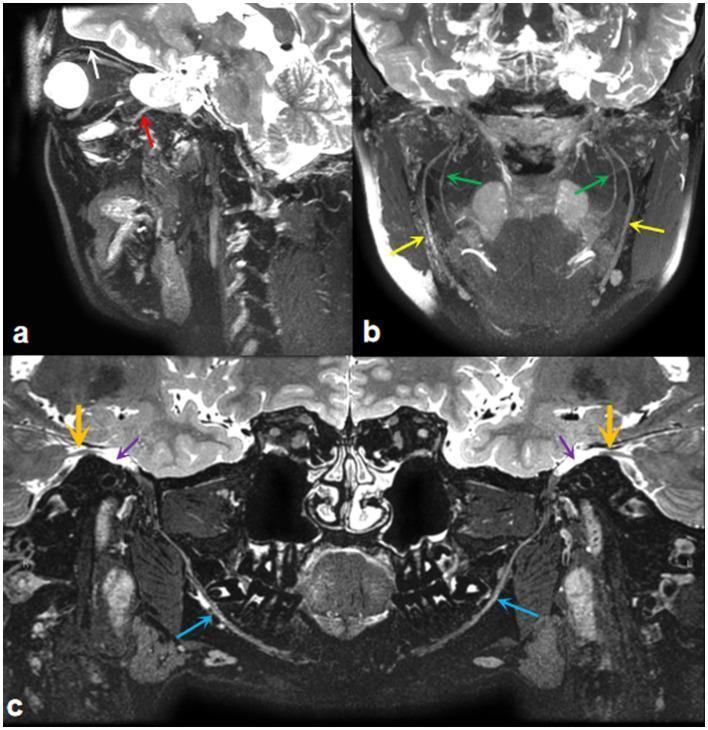
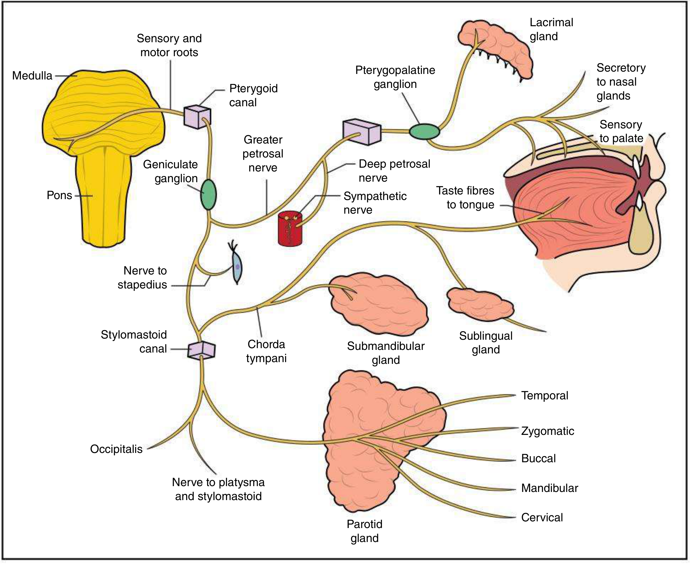
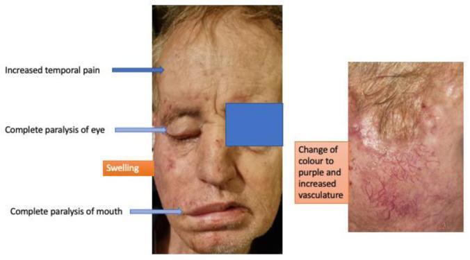
- Nuclear/peripheral (e.g., Bell's palsy) lesion → complete ipsilateral facial paralysis including frontalis and orbicularis oculi → lagophthalmos, paralytic ectropion of the lower lid, exposure keratopathy, and loss of the efferent limb of the corneal reflex (blink) despite intact corneal sensation.
- Bell's palsy accounts for 60-70% of facial nerve palsy cases; surgical decompression is not beneficial, but lid protection (lubrication, tape, tarsorrhaphy, or gold weight) is central to ophthalmic management of exposure risk.
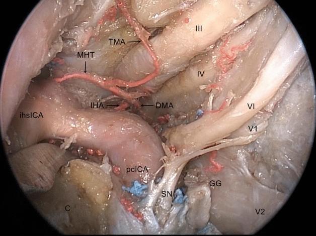
Bonus: combined 3D skull-base view (all four nerves together)
Quick summary table for exam recall
| Nerve | Exit from brainstem | Cavernous sinus position | Orbital entry | Key EOM/structure | Classic PG-ophthal correlate |
|---|---|---|---|---|---|
| III | Midbrain-pons junction (ventral) | Lateral wall, superior | Within annulus of Zinn (SOF) | LPS, SR, MR, IR, IO + pupil/accommodation | Pupil-involving palsy = aneurysm until excluded |
| IV | Dorsal midbrain (only dorsal-exiting CN) | Lateral wall, below III | Outside annulus of Zinn (SOF) | Superior oblique | Head tilt, worse on downgaze/adduction |
| V (V1) | Pons (Gasserian ganglion in Meckel's cave) | Lateral wall, below IV | Within annulus of Zinn (SOF) | Sensory: cornea, lids, forehead | Corneal reflex afferent; neurotrophic keratopathy |
| VII | Pons (via IAM, facial canal) | Not in cavernous sinus | Not orbital - stylomastoid foramen | Orbicularis oculi (blink) | Lagophthalmos/exposure keratopathy in palsy |
Atlas style whole pathways in one image one by one
oculomotor nerve pathway from midbrain nucleus to extraocular muscles labeled atlas diagram
trochlear nerve full course from brainstem nucleus to superior oblique muscle labeled diagram
trigeminal nerve three divisions ophthalmic maxillary mandibular full pathway labeled diagram
facial nerve full course from brainstem nucleus through temporal bone to face muscles labeled diagram
trigeminal nerve diagram divisions
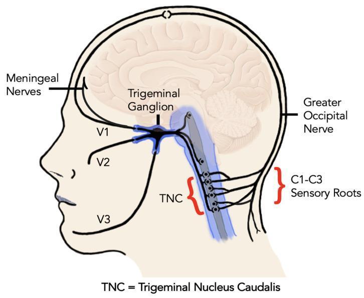
Anatomical diagram in a sagittal profile illustrating the neuroanatomy of the trigeminocervical complex and its primary sensory pathways. The central focus is the trigeminal ganglion, showing the three major divisions of the trigeminal nerve (CN V): the ophthalmic nerve (V1) innervating the forehead and eye region, the maxillary nerve (V2) serving the mid-face, and the mandibular nerve (V3) supplying the lower jaw. Superiorly, the meningeal nerves are shown branching toward the intracranial space. Posteriorly, the diagram highlights the convergence of trigeminal and cervical sensory inputs in the brainstem and upper spinal cord, specifically at the Trigeminal Nucleus Caudalis (TNC). The TNC is shown receiving afferent fibers from the trigeminal nerve as well as the C1-C3 sensory roots. Additionally, the greater occipital nerve is depicted at the posterior cranium. This illustration demonstrates the structural basis for referred pain mechanisms and central sensitization in conditions like migraine and other primary headache disorders by showing the functional integration of cranial and upper cervical sensory information.
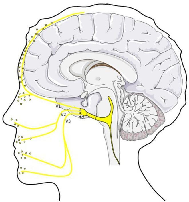
An anatomical diagram in sagittal profile illustrating the trigemino-vascular system and its role in migraine pathophysiology. The central focus is the trigeminal ganglion (TG), from which three primary divisions of the trigeminal nerve (CN V) emerge: the ophthalmic (V1), maxillary (V2), and mandibular (V3) branches. These peripheral afferents are shown innervating the scalp, forehead, mid-face, and jaw regions, with yellow dots indicating the release of Calcitonin Gene-Related Peptide (CGRP) at nerve terminals. Intracranially, the diagram highlights the ophthalmic division's (V1) innervation of the dura mater and cerebral vasculature. Centrally, a primary nerve tract is depicted traveling from the trigeminal ganglion toward the brainstem and trigeminocervical complex (TCC), representing the pathway for nociceptive signal transmission. The illustration combines a stylized mid-sagittal section of the human brain—including the cerebrum, cerebellum, and brainstem—with a facial outline to demonstrate the neuroanatomical connection between intracranial meningeal structures and peripheral facial sensory distribution.
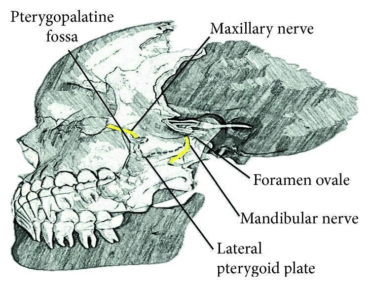
Anatomical diagram of a lateral view of the human skull, specifically focusing on the deep facial nerves and related osteological landmarks. The illustration highlights the trigeminal nerve (CN V) divisions using yellow color-coding. The maxillary nerve (V2) is shown exiting the cranial cavity through the foramen rotundum to enter the pterygopalatine fossa, located anterior to the lateral pterygoid plate. The mandibular nerve (V3) is depicted exiting via the foramen ovale, descending posterior to the lateral pterygoid plate. Key labels include the Pterygopalatine fossa, Maxillary nerve, Foramen ovale, Mandibular nerve, and Lateral pterygoid plate. The diagram serves as an educational resource for understanding the regional anatomy required for performing nerve blocks and identifying neural pathways within the infratemporal and pterygopalatine regions.
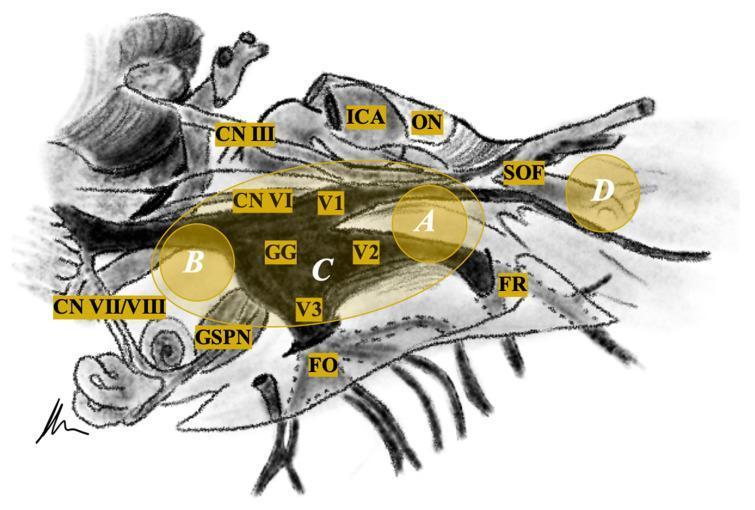
This medical schematic diagram illustrates the neuroanatomical relationships of the trigeminal nerve (CN V) and its surroundings, specifically designed for tumor localization and classification. The central feature is the Gasserian Ganglion (GG), which branches into three divisions: the Ophthalmic (V1) extending toward the Superior Orbital Fissure (SOF), the Maxillary (V2) toward the Foramen Rotundum (FR), and the Mandibular (V3) toward the Foramen Ovale (FO). Adjacent neurovascular structures are labeled, including the Internal Carotid Artery (ICA), Optic Nerve (ON), and Cranial Nerves III, VI, and VII/VIII complex. The Greater Superficial Petrosal Nerve (GSPN) is also indicated inferior to the ganglion. Overlaid on the anatomy are shaded yellow regions and white letters (A, B, C, D) representing a clinical classification system for trigeminal schwannomas: Type A (middle fossa), Type B (posterior fossa), Type C (dumbbell-shaped involving both fossa), and Type D (extracranial/extradural). This diagram serves as a surgical planning guide for neurosurgeons and medical students focusing on skull base pathology.
This medical anatomical diagram features two clinical photographs of a dry bone specimen, showing the osseous anatomy of the human orbital apex of the sphenoid bone. Image (A) provides an anterior view, highlighting the optic canal superomedially and the superior orbital fissure (SOF) inferolaterally. Key landmarks include the optic strut, which separates the optic nerve and ophthalmic artery from the SOF contents, and the maxillary strut, which separates the SOF from the foramen rotundum. Overlays illustrate the surgical decompression areas: the light green area denotes the medial wall of the optic canal, and the light blue area indicates the medial wall of the SOF. Image (B) presents a posterior view, showing the spatial relationship between the optic canal, SOF, foramen rotundum, and the carotid sulcus. The diagram identifies neurovascular structures passing through these apertures, including the optic nerve (CN II), oculomotor nerve (CN III), trochlear nerve (CN IV), and divisions of the trigeminal nerve (V1, V2). This resource is designed for advanced surgical planning in endoscopic endonasal decompression procedures.
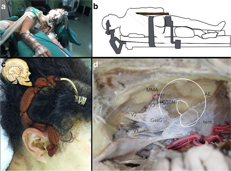
A multi-panel medical figure demonstrating surgical positioning and middle fossa neuroanatomy for a middle fossa approach (MFA). Panel A (Clinical Photograph) and B (Schematic Illustration) show a patient in the left lateral decubitus position for neurosurgery. The head is slightly extended toward the contralateral side with the ipsilateral shoulder retracted inferiorly to optimize the surgical corridor. Panel C displays a 'question mark' parieto-temporal skin incision behind the ear, with an inset skull diagram showing the underlying craniotomy boundaries. Panel D is a Cadaveric Specimen showing the superior view of the middle cranial fossa floor after dural peeling. Key anatomical landmarks are labeled: the Gasserian ganglion (GssG) and its divisions (V1, V2, V3); the greater superficial petrosal nerve (GSPN) running anteriorly; the middle meningeal artery (MMA) emerging from the foramen spinosum; and the arcuate eminence (AE) indicating the superior semicircular canal. A white outline simulates the relative location of a facial nerve schwannoma within the 'rhomboid construct' of the petrous bone, highlighting its relationship to the tentorium cerebelli (tent) and trigeminal complex.
fourth nerve palsy anatomy diagram
trochlear nerve nucleus decussation midbrain
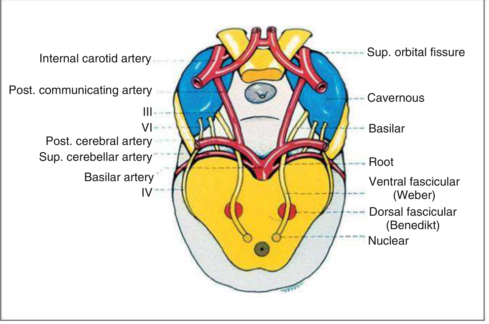
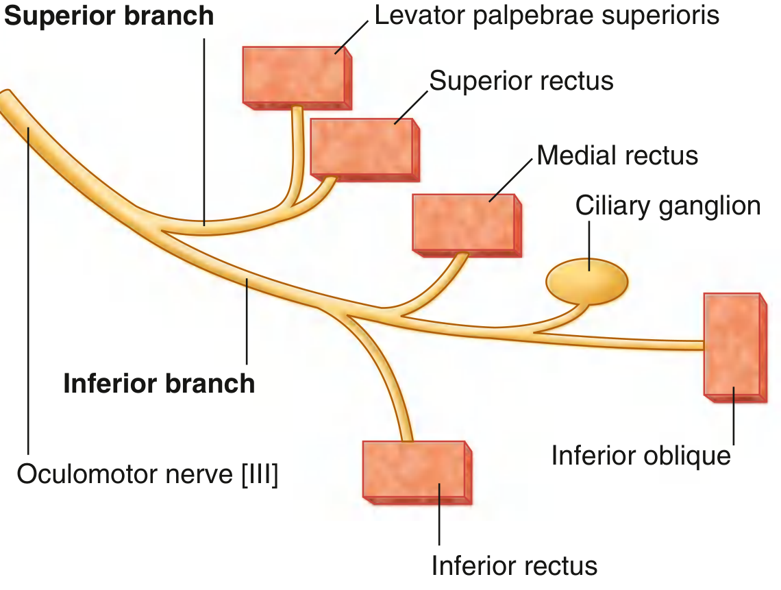
1. CN III — Oculomotor Nerve (whole pathway: midbrain nucleus → orbit)
2. CN IV — Trochlear Nerve (whole pathway: dorsal midbrain nucleus → superior oblique)
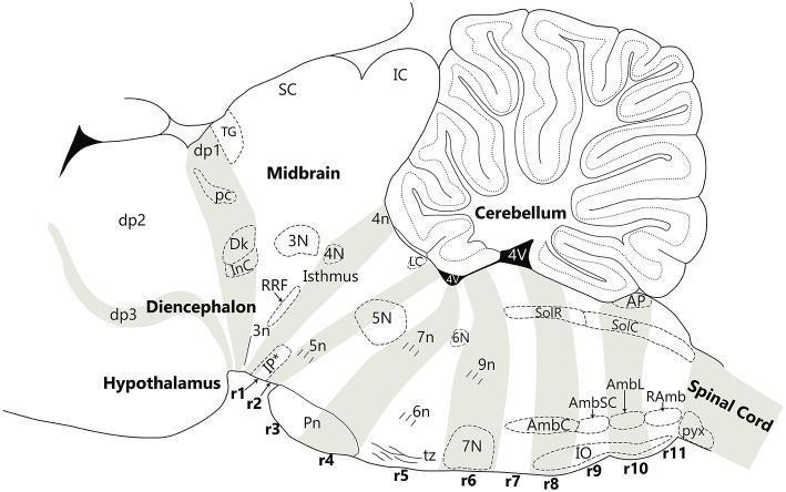
3. CN V — Trigeminal Nerve (whole pathway: ganglion → three divisions → brainstem)
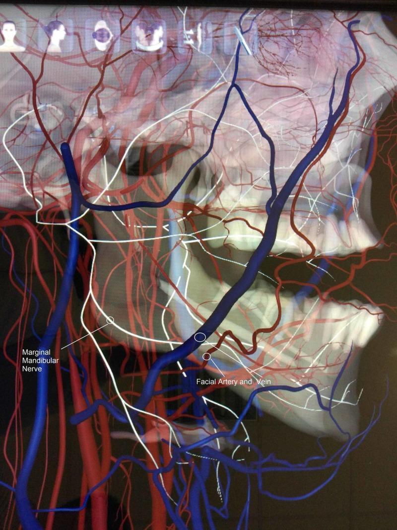
4. CN VII — Facial Nerve (whole pathway: pontine nucleus → face)