Stitch radiography in detail add every point you know search various research papers , books , articles and give me notes on it in detail , like definition, principle, history, techniques , process , components etc u want to add , and also give me diagram to add in my notes
stitch radiography full-length lower limb imaging
stitch radiography definition principle technique components detailed
PMID: 36311950
panoramic radiography long cassette whole leg alignment
image stitching digital radiography lower extremity alignment
stitch radiography full length lower limb x-ray
full length lower limb radiograph mechanical axis HKA angle measurement
PMID: 38443696
stitch radiography technique multiple exposures panoramic digital radiograph stitching process
📋 STITCH RADIOGRAPHY — Comprehensive Notes
1. DEFINITION
"Full-length lower limb x-rays are used to diagnose and plan surgical procedures such as Total Knee Arthroplasty (TKA) and High Tibial Osteotomy (HTO). Due to the size limitation of digital radiography, panoramic x-ray images cannot be obtained in a single exposure, necessitating multiple exposures and image stitching." — Alkhatatbeh et al., Frontiers in Surgery, 2022 [PMID: 36311950]
2. SYNONYMS & RELATED TERMS
| Term | Context |
|---|---|
| Full-length radiograph | General clinical usage |
| Long-leg radiograph | Lower limb orthopaedics |
| Scanogram / Orthoroentgenogram | Limb-length measurement |
| Teleroentgenogram | Historical film-based term |
| Goniometry (radiographic) | Lower limb axis assessment |
| EOS imaging | Modern low-dose biplanar stitched system |
| Panoramic radiography | Spine and extremity variants |
3. HISTORY & EVOLUTION
3.1 Film Era (Pre-digital)
- Early 20th century: Initial attempts using long cassettes (≥ 91 cm) placed along the full length of the limb, with a single exposure from a distant focus. Called teleroentgenography (tele = distant, to reduce magnification).
- Clinicians used 14 × 17 inch (35 × 43 cm) film cassettes butted end-to-end. The resulting films were physically overlapped and taped together.
- Scanography emerged as a technique where the X-ray tube moved along a slit-collimated beam past a stationary long cassette — reducing parallax and geometric distortion.
- Problems: parallax error, patient movement between exposures, magnification differences, and physical film misalignment at the stitching line.
3.2 Computed Radiography (CR) Era (1980s–2000s)
- Phosphor imaging plates replaced film but remained physically limited in size (~35 × 43 cm max).
- Manual stitching was performed in dedicated PACS/workstation software by overlapping landmark structures (e.g., joint outlines).
- Introduction of dedicated long-cassette CR systems (e.g., 35 × 91 cm plates) partially reduced the need for stitching.
3.3 Digital Radiography (DR) / Flat-Panel Detector Era (2000s–present)
- Flat-panel detectors (FPDs) are typically 43 × 43 cm (17 × 17 inch) — too short for full lower limb coverage.
- Software-based automated stitching algorithms were developed, using feature-detection methods to merge multiple overlapping images.
- EOS® system (EOS Imaging, France) introduced simultaneous biplanar (AP + lateral) full-body imaging in a single upright pass using slot-scanning technology — the gold standard by the 2010s.
- 2022: Canny-edge-detection-based automated stitching using bone edge detection + Wavelet fusion achieved 100% accuracy and 3-second stitching time (Alkhatatbeh et al., 2022).
4. PRINCIPLE
4.1 Fundamental Radiographic Principle
4.2 The Stitching Principle
- Multiple overlapping exposures are made — each capturing a segment of the limb (e.g., hip-to-knee frame, knee-to-ankle frame).
- Each frame is acquired sequentially — the X-ray tube/detector shifts along the limb axis between exposures.
- The individual images are aligned using common anatomical landmarks present in the overlapping region (e.g., tibial plateau, femoral condyles) as registration points.
- The aligned images are blended (alpha blending, wavelet fusion, or feathering) to eliminate visible seam artifacts at the junction.
- The resulting composite image simulates what a single large-format exposure would have produced.
4.3 Weight-Bearing Principle
- Physiological joint loading is reproduced.
- True mechanical axis deviation (varus/valgus) is visible under load.
- Soft tissue compression across joints mimics functional anatomy.
- Non-weight-bearing images underestimate deformity severity.
5. INDICATIONS (CLINICAL USES)
Lower Limb
| Indication | Purpose |
|---|---|
| Osteoarthritis assessment | Evaluate joint space narrowing, varus/valgus |
| Pre-operative planning for Total Knee Arthroplasty (TKA) | Measure HKA angle, plan implant alignment |
| High Tibial Osteotomy (HTO) planning | Determine angle of correction, osteotomy site |
| Distal Femoral Osteotomy | Valgus correction planning |
| Limb Length Discrepancy (LLD) | Measure true leg length differences |
| Paediatric deformity (genu varum/valgum) | Follow physiological correction with age |
| Post-operative TKA/THA follow-up | Assess restoration of neutral axis |
| Limb-salvage oncology | Monitor expandable prosthesis, LLD |
| Fracture planning | Long bone deformity/malunion assessment |
Spine
| Indication | Purpose |
|---|---|
| Scoliosis (adolescent/adult) | Cobb angle measurement, curve classification |
| Sagittal balance assessment | Measure SVA, PI, LL, TK |
| Spinal fusion pre/post-op | Full instrumentation view |
| Degenerative spinal deformity | Global alignment measurement |
Upper Limb (less common)
- Full-length humerus/forearm in specific deformity/fracture contexts.
6. ANATOMY ASSESSED ON STITCH RADIOGRAPHY (LOWER LIMB)
- Pelvis (both hip joints, femoral heads)
- Femoral shafts (bilateral)
- Knee joints (distal femur, proximal tibia, fibula head)
- Tibial and fibular shafts
- Ankle joints
- Optionally: foot
7. KEY MEASUREMENTS & ANGLES
7.1 Hip-Knee-Ankle (HKA) Angle
- A line drawn from the centre of the femoral head to the centre of the ankle (specifically the centre of the talus).
- The mechanical axis of the lower limb.
- Normal: 0° ± 3° (slight valgus in females is physiological).
- Varus = HKA < 0° (medial deviation)
- Valgus = HKA > 0° (lateral deviation)
- Gold-standard measurement from standing full-length radiograph.
7.2 Mechanical Axis Deviation (MAD)
- Horizontal distance (mm) between the mechanical axis line and the centre of the knee joint.
- Normal: passes 8–10 mm medial to the knee centre (within medial compartment).
7.3 Weight-Bearing Line Ratio (WBL)
- Position of the mechanical axis on the tibial plateau expressed as a percentage of plateau width.
- Normal: ~43–50% (near centre).
- Used for HTO correction planning; target point = 62.5% for lateral shift in varus correction.
7.4 Joint Line Convergence Angle (JLCA)
- Angle between the distal femoral joint line and proximal tibial joint line.
- Reflects medial/lateral soft-tissue laxity component vs bony deformity.
7.5 Femoral and Tibial Mechanical/Anatomical Angles
- mLDFA (mechanical Lateral Distal Femoral Angle): 85°–90° normal
- mMPTA (mechanical Medial Proximal Tibial Angle): 85°–90° normal
- Identify whether deformity is femoral or tibial in origin
7.6 Limb Length (LLD)
- True length from femoral head centre to ankle mortise.
- Bilateral comparison.
8. TECHNIQUE / PROCEDURE
8.1 Patient Preparation
- Patient changes to gown; remove metallic objects, jewellery.
- Ensure full lower limb is exposed from hip to ankle.
- Gonadal shielding where feasible (balanced against diagnostic field requirements).
8.2 Patient Positioning (Weight-Bearing)
- Patient stands erect on the platform in front of the detector.
- Feet positioned: shoulder-width apart OR in standardised position (feet together, first metatarsals and heels touching, toes pointing forward).
- Patellae facing forward (critical — ensures correct rotational alignment).
- Knees in full extension (no flexion).
- Hands placed on shoulders or holding side handles to avoid superimposition over pelvic/hip region.
- Both lower limbs imaged simultaneously on bilateral studies.
8.3 X-ray Parameters (Typical)
| Parameter | Value |
|---|---|
| Tube voltage (kVp) | 70–90 kVp (lower limb); 90–110 kVp (pelvis) |
| mAs | 10–25 mAs per exposure |
| Focus-to-detector distance (FDD) | 300–400 cm (long FFD reduces magnification) |
| Collimation | Tight — to body width |
| Projection | Anteroposterior (AP) standing |
8.4 Number of Exposures
- 2-frame stitch: Hip-to-knee + Knee-to-ankle (most common)
- 3-frame stitch: Hip / Knee / Ankle (for tall patients or large field)
- Each frame overlaps the previous by 10–20 cm to provide registration landmarks
8.5 Overlap Region (Critical)
- The overlapping zone between adjacent frames must include a bony landmark (e.g., tibial plateau/condyles).
- Without adequate overlap, stitching algorithms fail or produce gross misregistration.
9. IMAGE STITCHING PROCESS
Step-by-Step Stitching (Manual & Automated)
Frame 1 (Hip region) + Frame 2 (Knee region) + Frame 3 (Ankle region)
          ↓                        ↓                       ↓
     Overlap zone A          Overlap zone B
          ↓
  STEP 1: Pre-processing
  → Normalise brightness/contrast across frames
  → Apply flat-field correction
          ↓
  STEP 2: Feature Detection / Registration
  → Identify matching anatomical landmarks in overlap zones
  → Methods: SIFT, SURF, ORB, or Canny edge detection
  → Bone edges detected as registration features
          ↓
  STEP 3: Image Alignment (Transformation)
  → Rigid or affine transformation applied
  → Frames shifted/rotated to align bone contours
          ↓
  STEP 4: Image Fusion (Blending)
  → Alpha blending (weighted pixel average in overlap zone)
  → OR Wavelet domain fusion (frequency-based)
  → OR Gradient blending
          ↓
  STEP 5: Output
  → Single composite full-length radiograph
  → DICOM format stored in PACS
9.1 Manual Stitching (Traditional)
- Performed on dedicated PACS workstations or dedicated software (e.g., Sectra, Horos, OsiriX).
- Operator manually aligns landmarks in overlapping zones.
- Time: 3–10 minutes per case.
- Subject to inter-observer variability.
9.2 Automated Stitching (Modern)
- Feature-based: Detects anatomical features (bone edges, joint contours) using computer vision algorithms.
- Canny algorithm (Alkhatatbeh et al., 2022): Detects bone edges → aligns them → fuses using Wavelet form domain. P-value 0.974 vs. manual; stitching time = 3 seconds.
- Intensity-based: Maximises normalised cross-correlation in the overlap zone.
- AI/Deep learning: Emerging convolutional neural networks (CNNs) for automated landmark detection and registration.
9.3 Common Stitching Artefacts
| Artefact | Cause | Effect |
|---|---|---|
| Step artefact / Mismatch | Bone misalignment at junction | False axis measurement |
| Ghost/double contour | Poor registration | Cortical duplication |
| Brightness banding | Exposure difference between frames | Density discontinuity |
| Magnification mismatch | Different FFDs per frame | Scale discrepancy |
| Patient movement artefact | Motion between frames | Anatomy shift |
10. COMPONENTS / EQUIPMENT
10.1 X-ray Generator and Tube
- High-frequency generator.
- Tube with rotating anode (for heat loading across multiple exposures).
- Collimator with tight field restriction.
10.2 Detector System
- Flat-panel detector (FPD): Amorphous selenium or cesium iodide scintillator, typically 43 × 43 cm.
- Long cassette CR systems: Up to 35 × 91 cm imaging plates (reduces frames needed).
- Motorised bucky/column: Moves the detector vertically between exposures under programmable control.
10.3 Patient Stand / Platform
- Elevated non-radio-opaque platform with foot markings.
- Alignment arrows for foot placement standardisation.
- Side handles for patient stability.
- Some systems incorporate a calibration marker (radio-opaque ruler at known distance) for magnification correction.
10.4 Stitching Software
- Integrated into DR system (manufacturer proprietary).
- OR workstation-based PACS tools.
- Modern AI platforms (e.g., TraumaCad, Sectra Orthopaedic, mediCAD).
10.5 EOS® System (Advanced Dedicated System)
- Slot-scanning X-ray system using linear detectors.
- Patient stands in the EOS cabin; simultaneous frontal + lateral low-dose images acquired.
- No "stitching" needed — single continuous image.
- Dose ~50–80% lower than conventional standing radiography.
- Generates 3D skeletal models from biplanar images.
11. RADIATION DOSE CONSIDERATIONS
| Method | Approximate Effective Dose |
|---|---|
| Single standard AP knee | 0.005–0.01 mSv |
| 2-frame stitch lower limb | 0.05–0.2 mSv |
| 3-frame stitch (hip to ankle) | 0.1–0.3 mSv |
| EOS full-body | 0.05–0.1 mSv (ultra-low) |
| Full-spine stitch (scoliosis) | 0.5–1.5 mSv conventional |
12. QUALITY ASSURANCE (QA)
Geometric Accuracy
- Magnification must be uniform or corrected using a calibration sphere/ruler at the level of the anatomy.
- Each frame should have the same FFD.
- A 25 mm calibration ball at hip level is common — used to calculate true scale.
Rotational Accuracy
- Patellae must face directly forward.
- Rotational malalignment (foot external rotation) will falsely alter HKA measurements.
- A 2° rotation error can produce a ~1° change in the apparent HKA angle.
Patient Positioning Reproducibility
- Standardised foot templates/markings ensure reproducibility on serial studies.
- Studies show that full body weight axial pressure during supine CT scanograms is comparable to standing stitch radiographs for HKA/WBL/JLCA (Liu et al., Skeletal Radiology, 2024, PMID: 38443696).
Stitching Accuracy Verification
- Compare measured bone lengths on stitched image vs. expected anatomical values.
- On automated systems, accuracy is validated by comparing HKA angles to manually stitched gold-standard (Alkhatatbeh et al., 2022 — 100% accuracy rate).
13. INTERPRETATION — WHAT IS READ ON THE RADIOGRAPH
13.1 Mechanical Axis
- Draw a straight line from the centre of the femoral head → centre of the tibial spines → centre of the ankle mortise (talus).
- Normal: this line passes through or just medial to the knee centre.
13.2 Varus Deformity (Genu Varum)
- Mechanical axis passes medial to the knee.
- Associated with medial compartment OA.
- Indication for HTO or medialising tibial osteotomy.
13.3 Valgus Deformity (Genu Valgum)
- Mechanical axis passes lateral to the knee.
- Associated with lateral compartment OA.
- Indication for distal femoral osteotomy (DFO).
13.4 Limb Length Discrepancy
- Measured from femoral head centre to ankle mortise bilaterally.
- True (bone) LLD vs. apparent LLD (from pelvic tilt).
13.5 Site of Deformity
- Using mLDFA and mMPTA angles, deformity localised to:
- Femoral (distal femur valgus/varus)
- Tibial (proximal or mid-shaft)
- Combined (double-level osteotomy required)
14. APPLICATIONS IN SURGERY
14.1 Total Knee Arthroplasty (TKA)
- Pre-op: Measure HKA, plan implant size, coronal alignment target.
- Post-op: Verify restoration of neutral mechanical axis (ideal: HKA = 0° ± 3°).
14.2 High Tibial Osteotomy (HTO)
- Plan angle of correction using Fujisawa point method.
- Target WBL ratio = 62.5% for varus correction.
- Osteotomy line length and wedge width calculated from the full-length radiograph.
14.3 Distal Femoral Varus Osteotomy
- Indicated for valgus malalignment + lateral compartment OA.
- Mechanical axis drawn; angle alpha determined at the femoral correction site.
14.4 Scoliosis Surgery
- Pre-op Cobb angle, curve flexibility.
- Intra-operative stitched fluoroscopy for long-segment instrumentation.
- Post-op implant position and correction assessment.
14.5 Limb Reconstruction
- Malunion correction (femoral/tibial).
- Expandable prosthesis monitoring in oncology.
15. COMPARISON WITH OTHER MODALITIES
| Modality | Advantages | Disadvantages |
|---|---|---|
| Stitch radiography (standing) | Weight-bearing, accurate HKA, low cost, widely available | 2D only, radiation, stitching artefacts possible |
| MRI (upright) | No radiation, soft tissue detail | Expensive, limited availability, longer exam time |
| CT scanogram | High resolution, no stitching needed | No weight-bearing (conventional), higher radiation |
| Supine weight-bearing CT | Mimics standing mechanically | Newer technique, needs specialised equipment |
| EOS biplanar | Ultra-low dose, 3D modelling, simultaneous AP + lateral | Cost, availability, bulky system |
Liu et al. (2024, Skeletal Radiology, PMID: 38443696) demonstrated no significant difference between standing stitch radiography and supine weight-bearing CT scanograms (with full body weight applied) for WBL, HKA, and JLCA measurements.
16. LIMITATIONS & PITFALLS
- Patient movement between frames — most common source of error.
- Rotational malalignment — feet externally rotated alters HKA.
- Stitching artefacts — step artefact, double contour at junction.
- Magnification variation — if FFD differs per frame.
- Pelvic obliquity / scoliosis — alters apparent limb alignment.
- 2D limitation — cannot assess axial/sagittal plane simultaneously.
- Radiation dose — significant for serial paediatric studies.
- Weight-bearing ability — patients with pain/instability may not stand correctly.
- No soft tissue information — cartilage, ligaments not visible.
17. RECENT ADVANCES
| Advance | Description |
|---|---|
| Automated AI stitching | Canny edge + Wavelet fusion (3 sec, 100% accuracy — 2022) |
| AI landmark detection | Deep learning auto-identifies hip/knee/ankle centres |
| AI angle measurement | Automated HKA, WBL, mLDFA from stitched image |
| Weight-bearing CT | Supine CT with axial load as alternative |
| EOS 3D modelling | 3D bone models from biplanar stitch-free images |
| Robotic TKA navigation | Intraoperative HKA verification using fluoroscopic stitching |
| AR/VR overlay | Stitched radiograph integrated with surgical navigation |
Archer et al. (Skeletal Radiology, 2025, PMID: 40295351) evaluated AI-generated lower extremity radiographic measurements in patients with implants — showing high accuracy of automated systems.
18. DIAGRAMS
Diagram 1 — Full-Length Lower Limb Stitch Radiograph (Bilateral Standing)
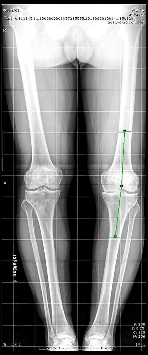
Diagram 2 — Full-Length Stitch Radiograph with HKA Axis Lines (Clinical)
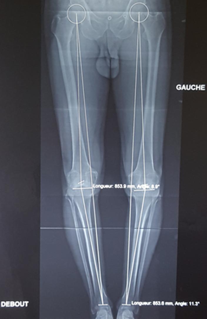
Diagram 3 — Patient Positioning for Stitch Radiography
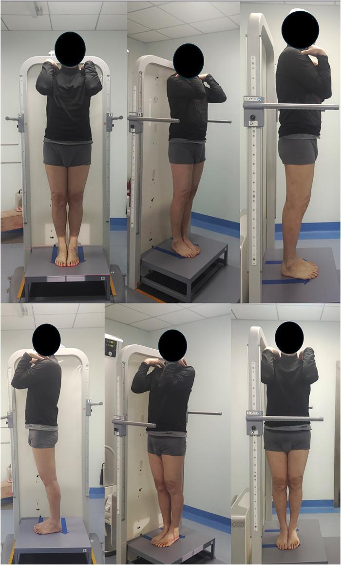
Diagram 4 — Mechanical Axis Measurement & Osteotomy Planning
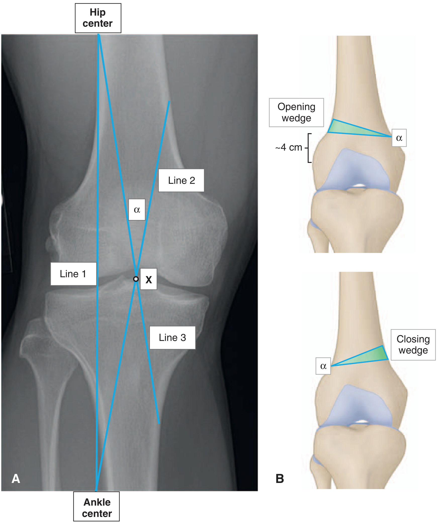
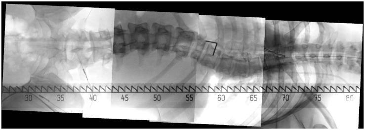
Diagram 5 — Intraoperative Spine Stitching (Panoramic C-arm)
19. SUMMARY TABLE
| Feature | Details |
|---|---|
| Definition | Multiple X-ray exposures stitched into one full-length composite image |
| Primary regions | Lower limb (hip to ankle), Spine (cervical to sacrum) |
| Position | Standing, weight-bearing (bilateral AP) |
| Frames | 2–3 overlapping exposures |
| Key measurement | HKA angle, WBL, MAD, limb length, mLDFA, mMPTA |
| Clinical use | TKA planning, HTO, DFO, scoliosis, LLD, deformity |
| Stitching | Manual (PACS workstation) or automated (AI/Canny/Wavelet) |
| Gold standard | Full-length standing AP radiograph |
| Modern alternative | EOS biplanar (simultaneous, ultra-low dose) |
| Key pitfalls | Rotation, patient movement, stitching artefact |
| Radiation dose | 0.05–0.3 mSv (2–3 frame lower limb) |
20. REFERENCES
- Alkhatatbeh T, Wang JL, Zhang WJ et al. "A new automatic stitching method for full-length lower limb radiography." Frontiers in Surgery, 2022. [PMID: 36311950] — DOI: 10.3389/fsurg.2022.1000074
- Liu X, Zhang B, Zhao C et al. "Assessment of lower limb alignment: supine weight-bearing CT scanograms compared with a standing full-length radiograph." Skeletal Radiology, 2024. [PMID: 38443696]
- Archer H, Xia S, Reine S et al. "Are artificial intelligence generated lower extremity radiographic measurements accurate in a cohort with implants?" Skeletal Radiology, 2025. [PMID: 40295351]
- Liodakis E, Kenawey M et al. "Upright MRI measurement of mechanical axis and frontal plane alignment: comparative study with weight bearing full length radiographs." Skeletal Radiology, 2011. [PMID: 21170524]
- Miller's Review of Orthopaedics, 9th Edition — Chapter on Imaging Studies (Knee) & Osteotomy Planning. — Miller's Review of Orthopaedics 9e, pp. 362, 466
- Rockwood and Green's Fractures in Adults, 10th Edition — Limb alignment and long-leg casting reference.
Key Exam Points:
- Stitch radiography = weight-bearing + multiple exposures + digital stitching
- HKA angle: measured from femoral head centre → talus centre; normal ≈ 0° ± 3°
- WBL ratio target for HTO varus correction = 62.5% of tibial plateau width
- EOS = slot-scan, biplanar, no stitching needed, ultra-low dose
- Main stitching artefact = step/mismatch artefact from patient movement
- Patellae must face directly forward for valid axis measurement