
Explain uterus anatomy
uterus anatomy diagram labeled parts
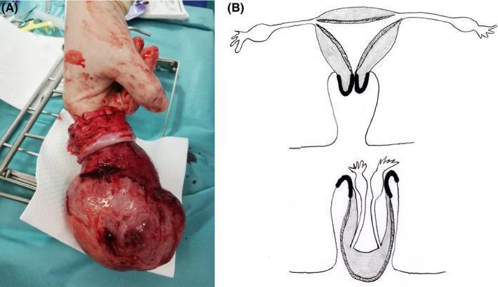
The image consists of two parts: (A) a clinical photograph of a surgically resected uterus and (B) an anatomical diagram illustrating uterine inversion. Panel A shows a gross pathological specimen of a total hysterectomy. The uterus appears as an enlarged, reddish, irregular mass with a bulbous uterine body and a distinct whitish, constricted cervical region. A surgical operator's finger is inserted into a central depression, representing the fundic invagination, which demonstrates the inverted state where the endometrial surface is on the exterior. Panel B provides a schematic comparison between normal uterine anatomy (top) and total uterine inversion (bottom). The diagram highlights the descent of the uterine fundus through the cervical canal and the subsequent 'cupping' or invagination of the adnexal structures (fallopian tubes and ovaries) into the resulting void. This visual provides clinical context for non-puerperal uterine inversion, often associated with heavy intrauterine masses like adenomyosis or myomas, emphasizing the structural transformation that occurs during this rare gynecological emergency.
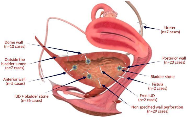
This medical anatomical diagram illustrates the various topographical sites of intrauterine device (IUD) migration and translocation into the urinary tract. The schematic depicts a sagittal view of the female pelvic anatomy, specifically highlighting the uterus, urinary bladder, and ureter. Labeled arrows indicate specific migration patterns and complications observed in clinical cases: IUDs embedded in the dome wall, anterior wall, and posterior wall of the bladder; those located outside the bladder lumen; and instances of ureteral involvement. Internal bladder complications are shown, including free-floating IUDs, non-specified wall perforations, and secondary bladder stone formation (calculi) encrusting the migrated device. The diagram also identifies IUD-related fistulas. Numerical case data (e.g., n=36 cases for IUD + bladder stone) are provided for each location, serving as a summary of clinical incidence for healthcare professionals and students studying long-term complications of contraceptive devices and secondary urological pathology.
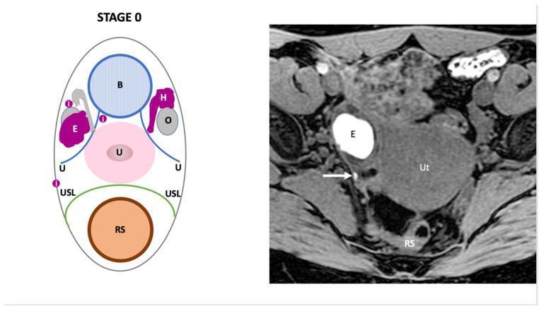
This dual-panel image provides a comparison between a schematic diagram and an axial T1-weighted fat-saturated MR image illustrating 'Stage 0' pelvic endometriosis. The left panel is a labeled diagram identifying key pelvic anatomy including the bladder (B), uterus (U), rectosigmoid (RS), ovaries (O), and uterosacral ligaments (USL). It highlights an endometrial cyst (E), hematosalpinx (H), and superficial peritoneal implants (i). The right panel shows a corresponding diagnostic MR image of the female pelvis. A prominent hyperintense (bright) cystic lesion labeled 'E' represents an ovarian endometrioma, characteristic of blood-filled contents on T1-weighted fat-saturated sequences. Adjacent to this, a white arrow indicates a small focus of intermediate-to-high signal intensity corresponding to a superficial peritoneal implant located near the uterosacral ligament and rectosigmoid (RS). Other visible landmarks include the uterus (Ut) and pelvic musculature. The image demonstrates the diagnostic criteria for early-stage endometriosis (Endo-Stage MRI classification), focusing on the identification of superficial lesions and ovarian involvement without deep pelvic infiltration.
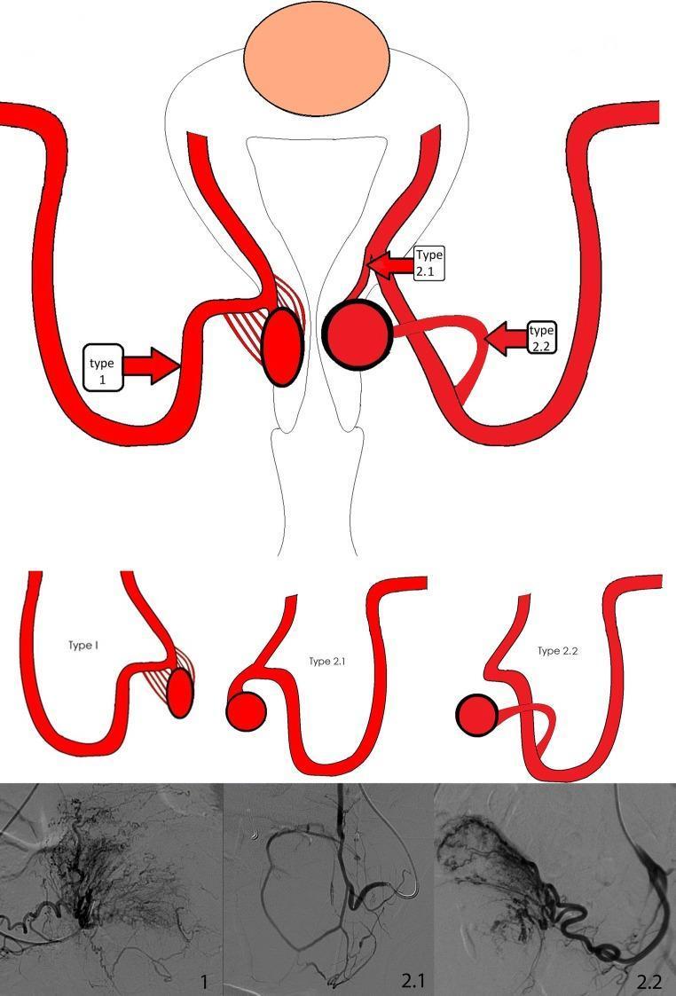
This composite educational graphic illustrates the vascular anatomy and angiographic classification of afferent branching arteries supplying cervical leiomyomata, essential for Uterine Artery Embolization (UAE). The top section features an anatomical diagram of the uterus and cervix with three distinct vascular patterns labeled. Type 1 represents an arterial plexus of multiple small feeding branches; Type 2.1 shows a solitary feeding branch originating proximally from the ascending uterine artery; and Type 2.2 depicts a solitary feeding branch originating distally. Red arrows and boxes indicate the target catheter positions for super-selective embolization for each type. The middle section provides simplified schematic drawings of these three vascular architectures. The bottom row presents corresponding Digital Subtraction Angiography (DSA) frames. Angiogram 1 displays a dense, complex network of tortuous vessels (plexus), while Angiograms 2.1 and 2.2 show more discrete, single-vessel supply paths. This material is designed for interventional radiologists to guide catheter placement and optimize clinical outcomes in the treatment of cervical fibroids.
uterus cross section layers endometrium myometrium perimetrium histology
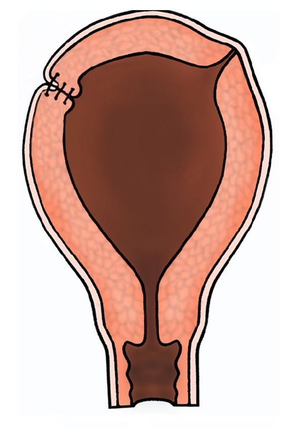
This medical illustration depicts a coronal cross-section of a human uterus, highlighting a surgical repair of the uterine wall. The organ is shown with its characteristic pear-shaped anatomy, including the fundus, body, and cervical canal. The uterine wall is stratified into three distinct layers: an outer perimetrium (serosa), a thick middle myometrium with a textured appearance, and a dark internal endometrial cavity. On the upper left aspect, specifically in the region of the uterine cornu, several dark, transverse inverting sutures are visible. These represent superficial polypropylene (Prolene) sutures applied to the serosal layer. The illustration demonstrates a post-operative state where the sutures serve to appose the seromuscular layers, promoting hemostasis and preventing the formation of peritoneal adhesions or fibrosis following surgical reconstruction. This diagram is utilized in obstetrics and gynecology to explain surgical techniques for managing myometrial weakness, cornual ectopic pregnancies, or uterine rupture repair.
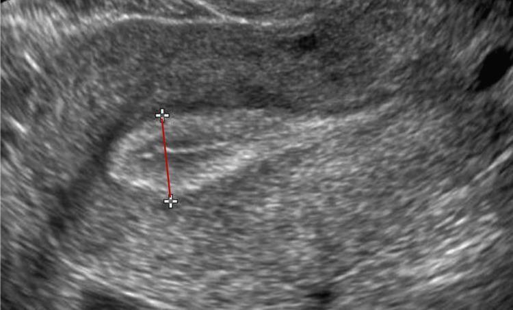
This diagnostic ultrasound image demonstrates a sagittal (longitudinal) cross-section of the uterus, focusing on the uterine cavity and the measurement of endometrial thickness (EMT). The endometrial lining appears as a relatively hypoechoic (darker) central region compared to the surrounding heterogeneous myometrium. The measurement technique is visually represented by a red electronic caliper line marked with '+' cursors at each end. This line extends perpendicular to the endometrial canal, from one stratum basalis interface to the opposite interface, marking the thickest portion of the functional endometrium. Such imaging is standard in reproductive medicine and gynecology to assess endometrial receptivity during assisted reproduction cycles (e.g., IVF or FET), where an EMT below 7 mm is typically categorized as a thin endometrium. The clear differentiation between the echogenic basalis layers and the hypoechoic endometrial canal is critical for accurate diagnostic measurement and clinical decision-making regarding embryo transfer feasibility.
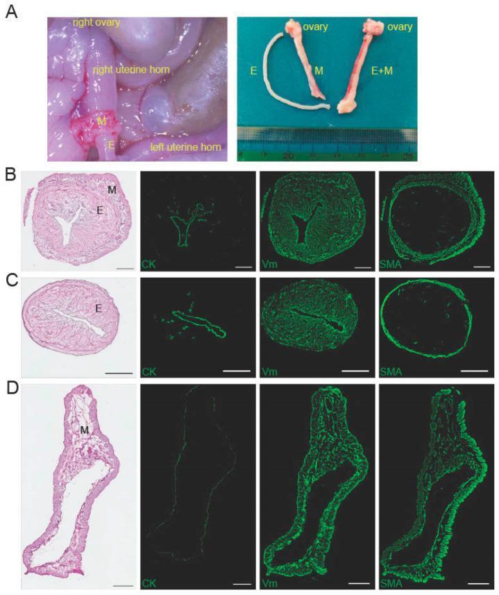
This composite educational graphic illustrates the surgical isolation and histological characterization of the rat endometrium for biomedical research. Panel A contains clinical photographs of the dissection process: the left image shows the in-situ separation of the endometrium (E) from the myometrium (M) within the uterine horn; the right image displays the isolated components (E, M, and intact E+M) alongside a metric scale. Panels B, C, and D present comparative cross-sectional histology (H&E stain) and immunofluorescence (IF) microscopy (scale bars = 500 µm). Panel B (Whole Uterus) shows intact luminal and muscular layers with cytokeratin (CK) highlighting the epithelium, vimentin (Vm) in the stroma and muscle, and smooth muscle actin (SMA) localized to the outer myometrium. Panel C (Peeled Endometrium) demonstrates a CK-positive epithelial lining and Vm-positive stroma, but an absence of SMA, confirming successful separation from the muscularis. Panel D (Remaining Outer Layer) shows a thick, SMA-positive and Vm-positive myometrial wall lacking internal CK-positive epithelial structures. These findings validate a method for isolating intact endometrial tissue for regenerative medicine studies.
Uterus Anatomy
Overview and Shape
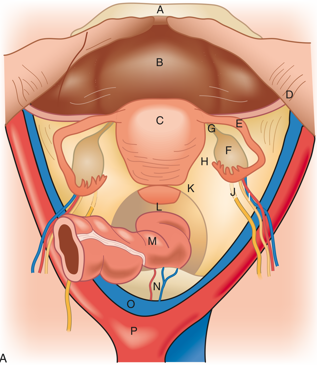
Parts of the Uterus
1. Fundus
2. Body (Corpus)
3. Cervix
- Internal os - communicates with the uterine cavity
- External os - opens into the vagina
Wall Layers (from outer to inner)
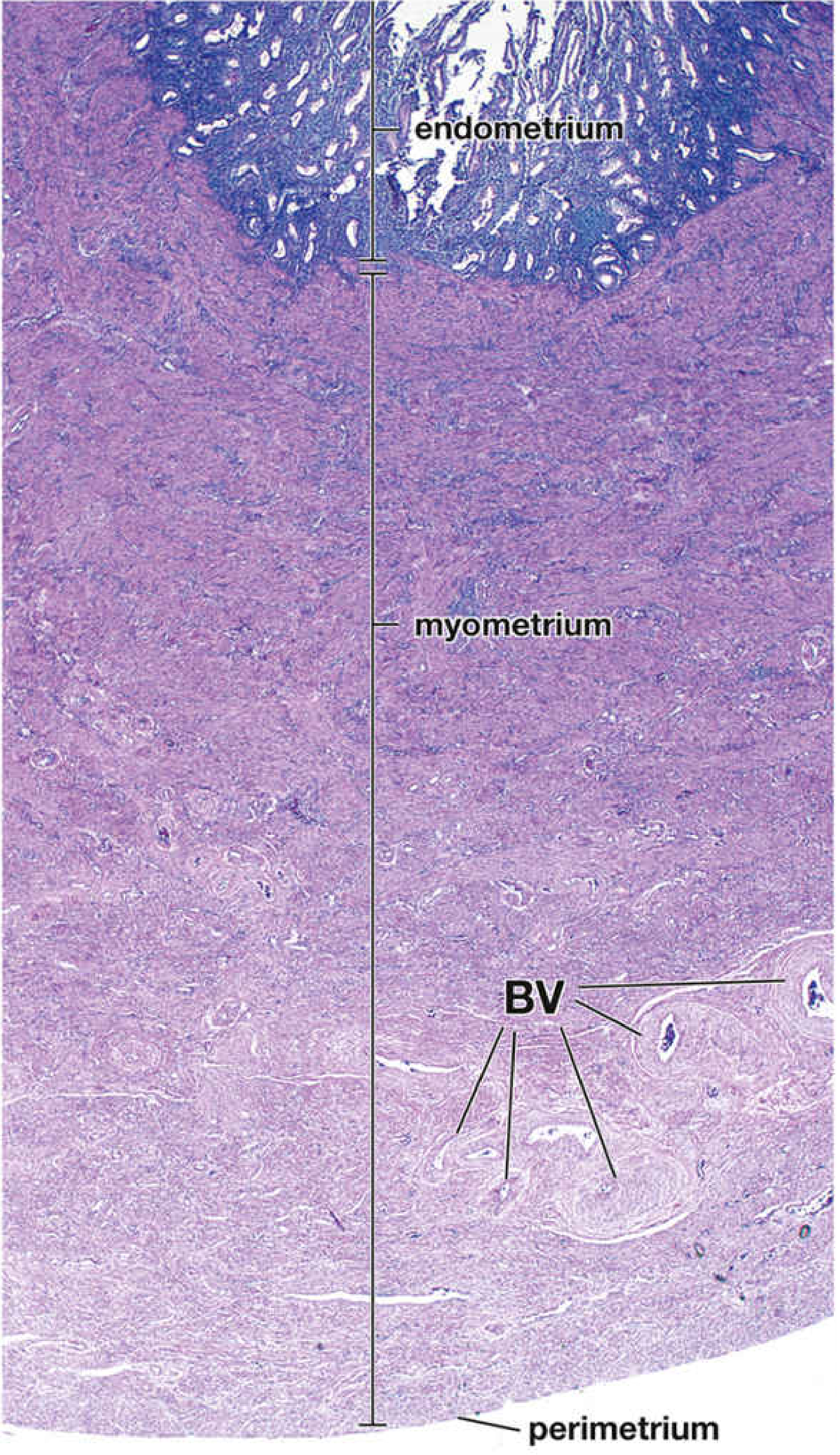
1. Perimetrium (outer)
2. Myometrium (middle - thickest layer)
- Inner layer (subvascular): smooth muscle bundles oriented parallel to the long axis
- Middle layer (stratum vasculare): the thickest sub-layer; contains a dense network of large blood vessels and lymphatics; muscle bundles run in a circular/spiral pattern - this is the primary expulsive layer during parturition
- Outer layer (supravascular): smooth muscle bundles again parallel to the long axis
Clinical note: Benign smooth muscle tumors of the myometrium are called leiomyomas (fibroids). During pregnancy, enlargement of smooth muscle cells enables this rapid uterine growth.
3. Endometrium (inner)
- Basal layer (stratum basale): The deep layer containing the blind ends of the uterine glands. Has its own independent blood supply; is NOT shed during menstruation. Acts as the regenerative source.
- Functional layer (stratum functionale): The superficial portion (further divided into a compact layer and a spongy layer). Undergoes cyclic proliferation and shedding during each menstrual cycle. At peak development, reaches 4-5 mm thickness.
- A thin compact layer - densely packed stroma around gland necks
- A thick spongy layer - edematous tissue with dilated, tortuous gland bodies
- A thin basal layer - containing gland blind ends
- The Developing Human, Moore & Persaud; Color Atlas of Human Anatomy, Thieme
Histological View
Ligaments and Support
| Ligament | Description |
|---|---|
| Broad ligament | A double-layered peritoneal fold extending from the lateral uterus to the lateral pelvic walls. Contains the fallopian tube, round ligament, ovarian ligament, uterine vessels, and nerves. Divides the pelvis into anterior and posterior compartments. Does not provide significant structural support. |
| Round ligament | Arises at the uterine cornu, passes through the inguinal canal, ends in the subcutaneous fat of the labia majora. Contains smooth muscle. Derived from the gonadal fold. |
| Cardinal ligament (Mackenrodt's ligament) | Condensation of connective tissue that fixes the cervix to the lateral pelvic wall. |
| Uterosacral (rectouterine) ligament | Dense subperitoneal connective tissue running from the cervix posterolaterally to the sacrum. Key suspensory component; attenuated in uterine prolapse. |
| Utero-ovarian ligament | Connects the uterus to the medial pole of the ovary. |
Blood Supply
- Arterial: The uterine artery (branch of the anterior division of the internal iliac artery) is the principal supply. It courses medially in the base of the broad ligament, crosses over the ureter (the "water under the bridge" relationship - surgically important to avoid ureteric injury), and ascends along the lateral uterus, giving branches to the cervix and anastomosing with the ovarian artery near the uterine cornu.
- Venous: A network of valveless veins forms the uterine venous plexus around the body and cervix, which drains into the internal iliac veins via the uterine veins.
Lymphatic Drainage
- Fundus/body → along the ovarian vessels to the para-aortic/lateral aortic nodes
- Body → to the external iliac nodes
- Round ligament pathway → to the superficial inguinal nodes
- Cervix → to the external iliac, internal iliac, obturator, and sacral nodes
- Color Atlas of Human Anatomy, Thieme; Campbell-Walsh-Wein Urology
Innervation
Relations
| Direction | Adjacent Structure |
|---|---|
| Anterior | Bladder (vesicouterine pouch between them) |
| Posterior | Rectum (rectouterine pouch = Pouch of Douglas between them) |
| Lateral | Broad ligament, uterine vessels, ureter |
| Inferior | Cervix → vagina |
| Superior | Intestinal loops |
Clinical Highlights
- Endometriosis: Endometrial tissue migrates from the uterine cavity to the ovaries or pelvic peritoneum. - Color Atlas of Human Anatomy, Thieme
- Curettage: Removes only the functional layer; the basal layer (closely interlinked with the sub-vascular myometrium) is preserved and regenerates the endometrium.
- Cervical cancer: Arises at the transformation zone between squamous and columnar epithelium of the cervix.
- Uterine prolapse: Results from attenuation of the cardinal-uterosacral complex, not the broad ligament.
- Ureteric injury: The uterine artery crosses over the ureter ~2 cm lateral to the cervix - this is the most common site of accidental ureteric ligation during hysterectomy.
Can we include per vaginal examination as clinical anotomy for uterus
bimanual pelvic examination uterus technique diagram
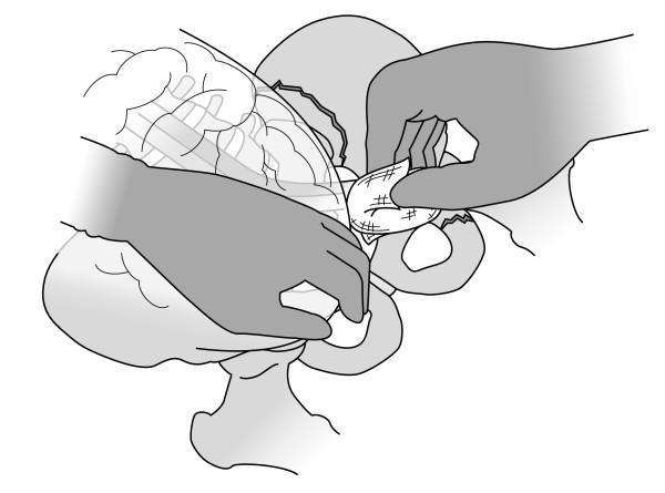
This medical illustration depicts a retroperitoneal pelvic packing procedure, typically used for hemorrhage control in cases of pelvic fracture. The line drawing shows a bimanual surgical technique within the left pelvic cavity. One hand is positioned medially and cranially, retracting the intact peritoneum and visceral contents (intestines) to create operative access to the retroperitoneal space. The second hand is shown inserting a surgical swab—illustrated with a cross-hatched texture indicating gauze—into the space adjacent to the pelvic ring. Key anatomical landmarks include the pelvic brim and the superior pubic ramus. The diagram emphasizes the manual dissection and packing of the pelvic sidewall down toward the coccyx. This visual serves as an educational guide for trauma surgery and emergency crisis management, specifically illustrating the sequence of manual retraction and tamponade via surgical packing following an extraperitoneal approach.
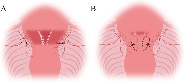
A schematic medical illustration depicting two stages of 'King’s combined uterine suture,' a surgical technique used for managing postpartum hemorrhage. The diagram uses shades of red to represent the uterus, cervix, and surrounding pelvic vasculature. Figure A illustrates parauterine vascular ligation, showing black sutures encircling the uterine artery and lateral vessels at the level of the lower uterine segment/cervical junction. Figure B demonstrates the longitudinal suture of the lower uterine segment, where the sutures are placed in a vertical 'U' configuration through the anterior and posterior uterine walls. Dashed lines indicate the internal path of the needle through the myometrium, while solid lines and 'X' symbols represent the external visible thread and knots. This illustration serves as a pedagogical guide for obstetricians and surgeons to visualize needle placement and suture geometry during uterine compression procedures, specifically aimed at devascularization and mechanical compression of the lower uterine segment.
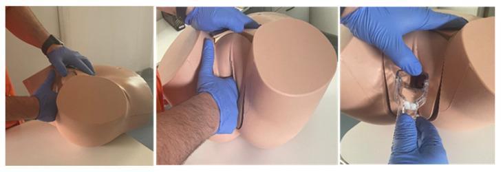
A series of three clinical photographs demonstrating the use of a Clinical Female Pelvic Trainer (CFPT) Mk 3 mannequin for gynaecological simulation. The mannequin is a skin-toned anatomical model representing the female lower torso and pelvic region in the lithotomy position, featuring realistic external genitalia including the labia majora and minora. The images illustrate standard steps of a gynaecological examination performed by an examiner wearing blue nitrile gloves. The first panel shows external palpation and inspection of the perineal area. The second panel demonstrates bimanual digital examination with the index and middle fingers inserted into the vaginal canal while the other hand stabilizes the pelvic model. The third panel shows the correct insertion technique of a clear plastic Graves or Cusco speculum into the vaginal opening to visualize the cervix. This visual material is intended for medical education to teach basic gynaecological skills, speculum placement, and bimanual palpation techniques.
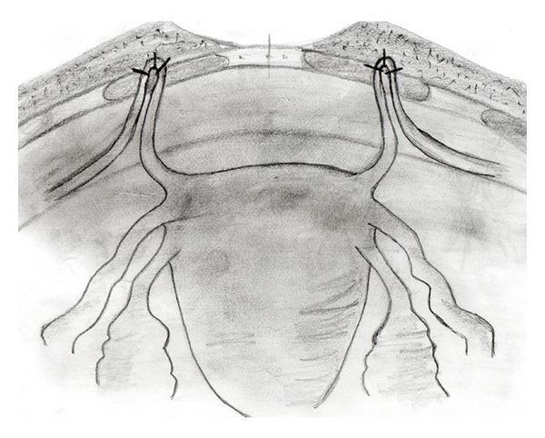
Anatomical Diagram: A black-and-white schematic illustration demonstrating the surgical fixation of the round ligaments to the anterior rectus fascia, likely for the management of pelvic organ prolapse. The diagram provides an anterior view of the uterus and its supporting structures. The uterine fundus is shown in the center, with the round ligaments extending bilaterally. These ligaments are depicted being pulled cranially and looped through small fenestrations in the rectus abdominis muscle layer. The apical 'ans' or loop of each round ligament is secured to the overlying fascia using three distinct sutures, represented by 'x' markers. Additional adnexal structures, including the fallopian tubes and utero-ovarian ligaments, are visible extending from the uterine cornua. The illustration emphasizes the anatomical relationship between the pelvic viscera and the abdominal wall fascia during a suspension procedure, highlighting the point of mechanical support and the method of non-absorbable suture fixation used to stabilize the uterine position.
Per Vaginal (PV) Examination - Clinical Anatomy of the Uterus
Patient Setup
Step 1 - Inspection of the External Genitalia
Step 2 - Speculum Examination
| Finding | Significance |
|---|---|
| Circular external os | Nulliparous cervix |
| Transverse slit-shaped os | Parous (previously delivered) cervix |
| Squamocolumnar junction (SCJ) / transformation zone | The red columnar endocervix transitions to reddish-pink squamous ectocervix - the site of CIN and cervical carcinoma |
| Mucopurulent discharge from os | Cervicitis, PID |
| Polyps projecting from os | Cervical or endocervical polyp |
| White lesion at SCJ that doesn't wipe off | Dysplasia, CIN, condyloma |
| Unusual bleeding from os | Cervical or uterine neoplasia |
Step 3 - Bimanual Pelvic Examination
A. Vagina and Cervix
- Vaginal tone - press downward at the perineum and ask patient to bear down; reveals cystocele, rectocele, or uterine descent
- Cervical position - normally felt in the midline at the vault; a posteriorly deviated cervix suggests an anteverted uterus, an anteriorly placed cervix suggests retroversion
- Cervical consistency - firm/rubbery normally (like a nose); softening (Hegar's sign) in early pregnancy
- Cervical os - closed vs. open (relevant in threatened vs. inevitable miscarriage)
- Cervical excitation (CMT - Cervical Motion Tenderness) - pain on moving the cervix side-to-side is a hallmark sign of pelvic inflammatory disease (PID)
B. Uterus Body Assessment (Bimanual)
| Parameter | Normal Finding | Abnormal |
|---|---|---|
| Position | Anteverted + anteflexed (most common) | Retroverted, retroflexed |
| Size | ~7.5 cm, pear-shaped | Enlarged in pregnancy, fibroids, malignancy |
| Shape | Regular, smooth, symmetric | Irregular/asymmetric = fibroid (leiomyoma) |
| Consistency | Firm | Soft in pregnancy; hard in fibroids |
| Mobility | Freely mobile | Fixed = adhesions, endometriosis, malignancy |
| Tenderness | Non-tender | Tender in PID, ectopic pregnancy |
| Surface | Smooth | Irregular nodular = fibroids or malignancy |
Normal position: The uterus is normally anteverted (tilted forward over the bladder) and anteflexed (body bent forward on the cervix). A retroverted uterus (~20% of women) is a normal variant but is associated with dyspareunia and dysmenorrhoea.
C. Fornices
- Posterior fornix - deep; the uterine fundus may be felt through it when retroverted. The pouch of Douglas (rectouterine pouch) is immediately behind - fullness or tenderness here suggests haemoperitoneum (ectopic pregnancy), pus (PID/abscess), or a pelvic mass
- Anterior fornix - shallow; the bladder lies anteriorly
- Lateral fornices - used to palpate the adnexa (tubes and ovaries)
D. Adnexal Palpation
- A normal fallopian tube is not palpable
- A normal ovary (~4 × 2 × 3 cm) is often not palpable; when felt, it is firm, mobile, and mildly sensitive
- Adnexal masses that can be detected: pedunculated fibroids, paraovarian cysts, tubo-ovarian abscesses (TOA), ectopic pregnancies
E. Rectovaginal Examination (follow-on)
-
Assessment of the posterior uterine wall and rectouterine pouch
-
Palpation of the uterosacral ligaments for nodularity (endometriosis)
-
Firmness between uterus and rectum (tumour deposits)
-
The uterus and cervix are palpable anteriorly; the cervix projecting through the anterior rectal wall is historically known as the "pons asinorum"
-
S. Das: A Manual on Clinical Surgery; Roberts & Hedges' Clinical Procedures
Uterine Size Assessment (Obstetric Context)
| Fundal Level | Approximate Gestational Age |
|---|---|
| Just above pubic symphysis | 12 weeks |
| Halfway between symphysis and umbilicus | 16 weeks |
| At the umbilicus | 20 weeks |
| Above the umbilicus (viable) | > 24 weeks |
- Rosen's Emergency Medicine
Summary: What PV Examination Tells You About Uterine Anatomy
| Clinical Finding | Anatomical Basis |
|---|---|
| Cervix felt at vaginal vault | Cervix protrudes 1-2 cm into vagina; surrounded by fornices |
| Fundus felt abdominally above pubis | Uterus sits in true pelvis; grows suprapubically in pregnancy |
| Cervical motion tenderness | Stretches uterosacral and broad ligaments, irritating peritoneum |
| Posterior fornix fullness | Proximity of pouch of Douglas to posterior fornix (only vaginal wall + peritoneum separate them) |
| Fixed, immobile uterus | Disruption of cardinal-uterosacral ligament complex by disease |
| Retroverted uterus - fundus palpable per rectum | Fundus tips posteriorly into the pouch of Douglas |
- Berek & Novak's Gynecology; Gray's Anatomy for Students