

Make a notes on ift by this topic with diagram and the each question all is of 15 mrk

Make a notes of ift by the topic which each one carry 15 mrk with proper diagram
interferential therapy IFT physiotherapy types physiological therapeutic effects electrodes
https://cbphysiotherapy.in/therapies-offered/interferential-…
interferential therapy IFT electrode placement diagram physiotherapy
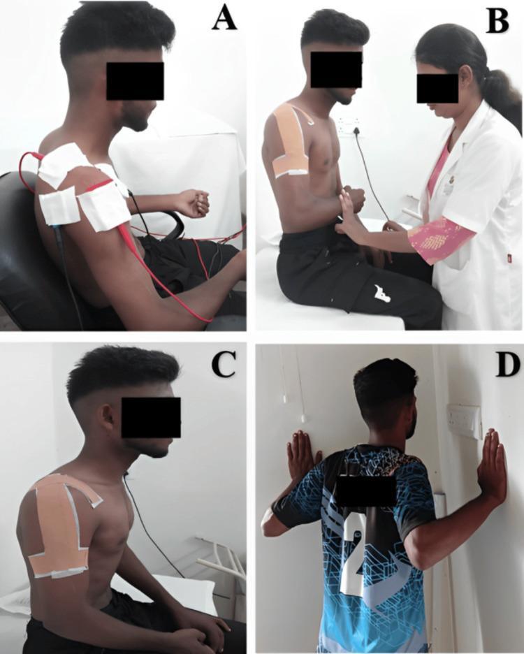
A multi-panel clinical photograph illustrating various stages of physiotherapy and rehabilitation for a shoulder injury. Panel A shows a seated patient receiving interferential therapy (IFT), with a four-pole electrode configuration using large white pads and red/black wires over the right shoulder and periscapular region for pain modulation. Panel B depicts a healthcare professional assisting the patient with isometric external rotation exercises; the patient's shoulder is stabilized with kinesiotherapy tape. Panel C focuses on specialized therapeutic taping, demonstrating an 'inverted J' application over the lateral and anterior deltoid aimed at increasing subacromial space. Panel D shows the patient performing active rehabilitation through wall push-ups in the scaption plane to improve scapular stability and muscle strength. The sequence represents a comprehensive orthopedic rehabilitation protocol ranging from passive pain management to active functional strengthening. The patient is a young adult male, and the setting is a clinical physiotherapy environment.
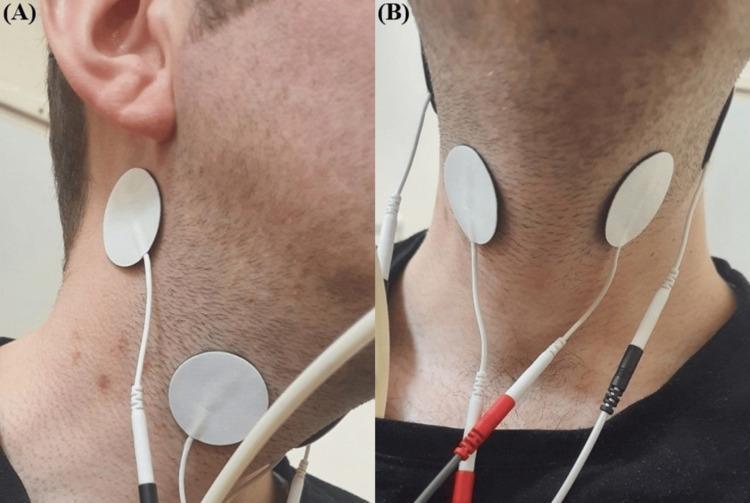
Clinical photograph in two views (A and B) demonstrating the electrode placement for Interferential Current (IFC) therapy, a neuromuscular electrical stimulation technique used in dysphagia rehabilitation. Image (A) provides a lateral (side) view of the neck, showing two circular, white surface electrodes adhered to the skin. One is positioned in the submental region near the angle of the mandible, and the second is placed inferiorly along the anterior border of the sternocleidomastoid muscle, targeting the superior laryngeal nerve pathway. Image (B) shows an anterior (front) view, illustrating the symmetrical placement of the electrodes on both sides of the laryngeal prominence. Thin, white lead wires with color-coded connectors (red and black) are attached to the electrodes, connecting to an external BTL-4000 Smart device. This setup is designed to stimulate pharyngeal and laryngeal muscles to improve swallowing function, specifically epiglottic inversion and hyoid bone movement, in patients with post-stroke dysphagia.
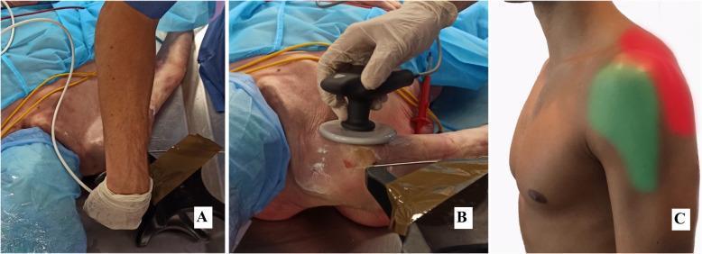
This composite educational image illustrates electrode placement for capacitive-resistive electric transfer (TECAR) therapy on the shoulder region. Panel A shows a clinical photograph of postero-superior application, with a clinician using a specialized handheld electrode near the acromioclavicular joint and upper trapezius. Panel B demonstrates the antero-lateral application, featuring a circular metallic electrode head being moved across the anterior deltoid and pectoral region. The setup includes blue sterile drapes, white conductive gel on the skin, and color-coded cabling (yellow and white). Panel C provides an anatomical diagram of the lateral shoulder, mapping the specific treatment zones: the antero-lateral area highlighted in green and the postero-superior area highlighted in red. This content is designed to teach physiotherapists and sports medicine clinicians the standardized positioning for high and low power resistive/capacitive interventions (HPR, LPR, HPC, LPC) used in rehabilitation or experimental physiotherapy research.
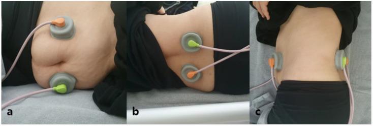
This composite of three clinical photographs illustrates the electrode placement for two-channel interferential current (IFC) therapy aimed at bowel stimulation. (a) Anterior view: Two circular grey electrodes with orange and green color-coded connectors are placed bilaterally on the anterior abdominal wall below the costal margin. (b) Posterior view: Two corresponding electrodes are positioned on the patient's back flanking the spine between the T12 and L4 vertebrae. (c) Lateral view: Provides a profile of the cross-sectional alignment, demonstrating how the electrodes are situated to create a crossing current path through the abdominal cavity. The patient is shown in a supine position on a medical table. Pink insulated wires connect each electrode to the IFC device. This procedural configuration is used in physical therapy and gastroenterology to modulate intestinal motility using a carrier frequency (e.g., 5 kHz) and beat frequency without inducing painful muscle contractions.
A clear educational physiotherapy diagram showing Interferential Therapy (IFT) principle: two medium frequency AC currents (4000 Hz and 4100 Hz) crossing inside body tissue, producing a beat frequency of 100 Hz at the intersection point. Label all components including electrodes, current pathways, interference zone, and beat frequency. Clean white background, labeled arrows, suitable for BPT students.
Educational physiotherapy diagram showing IFT electrode placement methods: left panel shows Tetrapolar/Quadripolar technique with 4 electrodes forming a square on a body part, right panel shows Bipolar technique with 2 electrodes. Show interference zone in center for tetrapolar. Label each type, electrode positions, and current paths. Clean, black and white diagram for medical students.
Medical education diagram showing IFT frequency effects table and sweep: 1-10 Hz causes muscle contraction/pumping effect, 10-50 Hz causes pain relief/endorphin release, 50-100 Hz causes pain relief (gate control), 90-100 Hz causes sedative effect, 100-150 Hz causes vasodilation/hyperemia. Arrow showing AMF sweep range. Clean labeled chart for BPT physiotherapy students.
INTERFERENTIAL THERAPY (IFT)
B.P.T. Degree Course - Medium Frequency Currents
Unit 2(i) - Complete Notes (15 Marks Each)
TOPIC (a): Define IFT and Its Types (15 Marks)
Definition
Key: The skin has low resistance to medium-frequency current, so it passes easily and deeply into tissues - unlike direct low-frequency current which causes painful skin sensations.
Principle of Interference
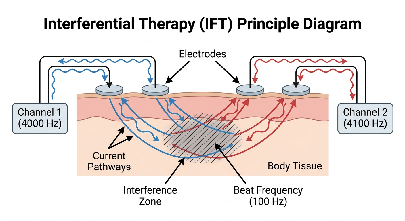
- Circuit 1: Fixed carrier frequency = 4000 Hz
- Circuit 2: Variable frequency = 4001 to 4250 Hz
- Beat (Interference) Frequency = Circuit 2 - Circuit 1
- e.g., 4100 - 4000 = 100 Hz AMF
- This beat frequency mimics low-frequency effects deep in the tissue.
Types of IFT
| Type | Description |
|---|---|
| True IFT (Quadripolar/Tetrapolar) | 4 electrodes placed on skin; interference occurs INSIDE the tissues |
| Pre-modulated IFT (Bipolar) | 2 electrodes; interference occurs INSIDE the machine; modulated current delivered |
| Stereodynamic IFT | 3 circuits, 6 electrodes; 3D interference pattern; used for deeper or larger areas |
Sub-types by Sweep Mode:
- Constant AMF - Fixed beat frequency (e.g., 100 Hz); for specific effect
- Rhythmic Sweep - Frequency automatically sweeps between a range (e.g., 1-100 Hz)
- Manual Sweep - Therapist adjusts manually
TOPIC (b): Physiological Effects of IFT (15 Marks)
1. Effect on Sensory Nerves
- 1-5 Hz: Stimulates A-delta and C fibres; mild tingling
- 10-50 Hz: Activates endorphin release (opioid mechanism); pain gate effect
- 50-100 Hz: Activates large diameter A-beta fibres - Gate Control Theory of Pain (Melzack & Wall, 1965)
- 90-150 Hz: Produces a sedative/analgesic effect on sensory nerves
2. Effect on Motor Nerves
- 1-10 Hz: Visible muscle contractions (individual twitches)
- 25-50 Hz: Tetanic muscle contraction - useful for muscle re-education and pumping
- >100 Hz: Muscle fatigue; nerve fatigue (Wedensky inhibition)
3. Effect on the Autonomic Nervous System
- Stimulation at lower frequencies causes vasodilation via axon reflex
- Increased local blood circulation
- Reduction in sympathetic tone (pain cycle reduction)
4. Effect on Circulation (Vascular)
- Vasodilation of arterioles and capillaries
- Increased local hyperemia (redness/warmth of area)
- Promotes tissue nutrition and removal of metabolic waste products
- Assists in reabsorption of oedema (via muscle pumping effect)
5. Effect on Tissue Healing
- Promotes fibroblast activity
- Accelerates collagen synthesis
- Promotes cell permeability changes
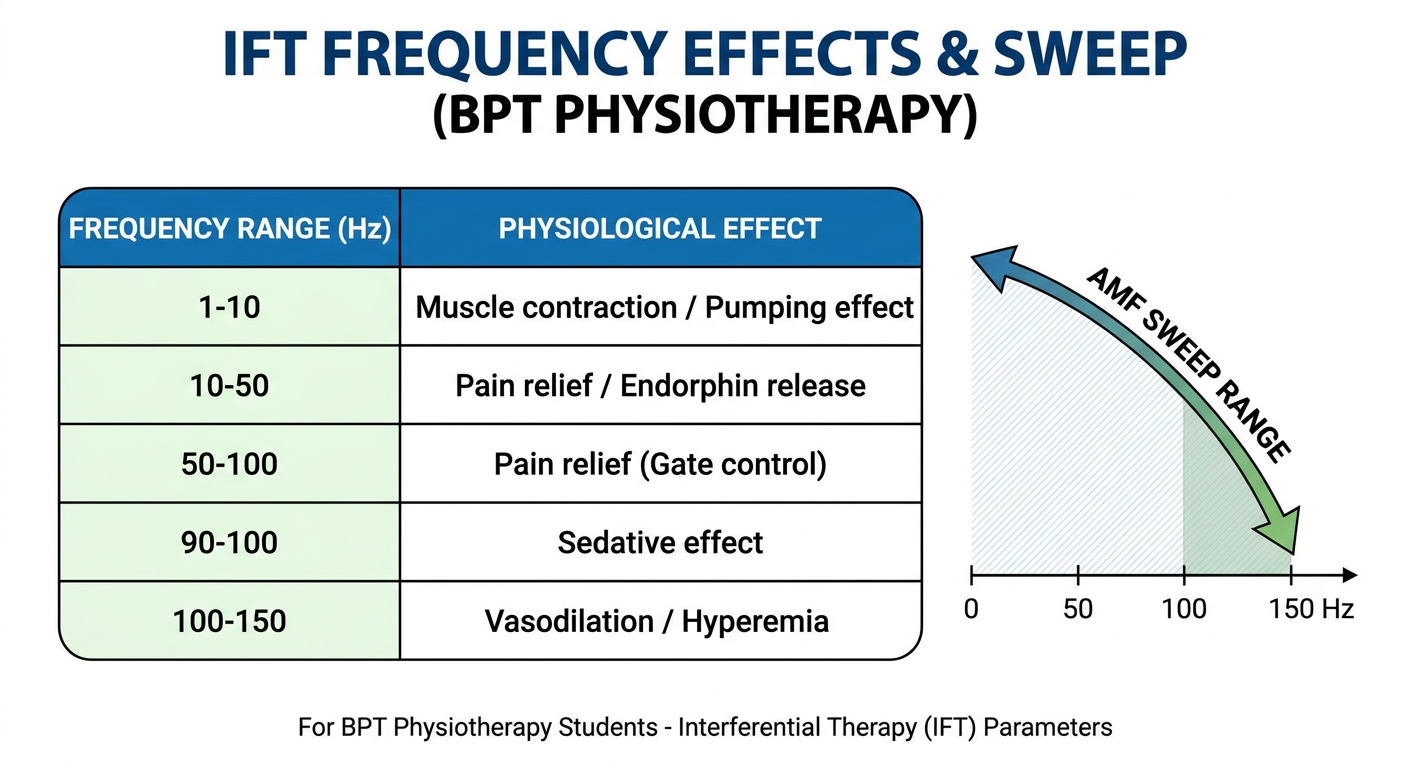
Diagram: Gate Control Theory in IFT
IFT Stimulation --> Large A-beta fibres activated
|
v
Interneuron in dorsal horn (Substantia Gelatinosa)
|
v
Pain gate CLOSED - C fibre signals BLOCKED
|
v
PAIN RELIEF ACHIEVED
TOPIC (c): Therapeutic Effects of IFT (15 Marks)
1. Pain Relief (Analgesia) - PRIMARY EFFECT
- Achieved via:
- Gate Control Theory (50-100 Hz)
- Endorphin/Enkephalin release (2-5 Hz)
- Physiological nerve block / Wedensky inhibition (>100 Hz)
- Reduction of sympathetic activity reducing pain cycle
2. Reduction of Oedema/Swelling
- Muscle contractions at 1-10 Hz act as physiological pump
- Improves lymphatic drainage
- Reabsorption of excess tissue fluid
- Best achieved with suction cup electrodes
3. Muscle Stimulation and Re-education
- 25-50 Hz range produces strong muscle contractions
- Useful in: post-surgical wasting, disuse atrophy, muscle spasm reduction
- Improves muscle tone and strength
4. Increased Blood Supply and Tissue Healing
- Vasodilation increases oxygen and nutrient delivery
- Helps resolve subacute and chronic inflammation
- Accelerates healing in soft tissue injuries
5. Reduction of Muscle Spasm
- Reduces trigger point sensitivity
- Relaxes spastic muscles via repetitive contraction-relaxation (tetanic fatigue)
- Effective in back pain, cervical spondylosis, fibromyalgia
6. Improvement in Joint Mobility
- Indirect effect via pain relief and muscle relaxation
- Used in osteoarthritis, frozen shoulder, sports injuries
Summary Table: Therapeutic Effects
| Effect | Mechanism | Frequency Used |
|---|---|---|
| Pain Relief | Gate Control, Endorphins | 50-100 Hz, 2-10 Hz |
| Oedema Reduction | Muscle pump | 1-10 Hz |
| Muscle Re-education | Motor nerve stimulation | 25-50 Hz |
| Vasodilation | Axon reflex | 100-150 Hz |
| Muscle Spasm Relief | Fatiguing tetanic contraction | 25-50 Hz |
TOPIC (d): Enumerate Appropriate Dose for Desired Physiological and Therapeutic Effects (15 Marks)
1. Carrier Frequency
- Standard: 4000 Hz (one circuit)
- Second circuit: 4000 + desired beat frequency (e.g., 4100 Hz for 100 Hz beat)
2. Beat Frequency (AMF - Amplitude Modulated Frequency)
| Desired Effect | AMF Range | Duration |
|---|---|---|
| Acute pain relief | 80-150 Hz | 10-15 min |
| Chronic pain | 2-10 Hz (endorphin) | 20-30 min |
| Muscle strengthening | 10-25 Hz | 15-20 min |
| Oedema reduction | 1-10 Hz (pump) | 15-20 min |
| Vasodilation | 100-150 Hz | 10 min |
| Muscle spasm relief | 20-50 Hz | 15-20 min |
3. Sweep (Spectrum)
- Fixed AMF: One specific frequency; concentrated effect
- Sweep AMF: Sweeps between two frequencies (e.g., 80-100 Hz) to prevent nerve accommodation
- Recommended: Use sweep to avoid habituation
4. Intensity (Current Output)
- Sensory level: Tingling without muscle contraction - for pain relief
- Motor level: Visible muscle contraction - for oedema/muscle stimulation
- Maximum tolerable: Strong contraction - for muscle strengthening
- Rule: Always increase from zero; stay within patient comfort
5. Treatment Duration
- Acute conditions: 10-15 minutes, once daily
- Subacute/Chronic: 15-30 minutes, 3-5 times per week
- Total course: 6-12 sessions typically
6. Electrode Size and Placement
- Larger electrodes = more comfortable stimulation
- Current density = Intensity ÷ Electrode area
- Position electrodes so current CROSSES the target tissue
Dose Summary Diagram
ACUTE PAIN ──────► High AMF (80-150 Hz), Sensory intensity, 10-15 min
CHRONIC PAIN ────► Low AMF (2-10 Hz), Sensory-Motor intensity, 20-30 min
MUSCLE PUMP ─────► Low AMF (1-10 Hz), Motor intensity, 15-20 min
VASODILATION ────► High AMF (100-150 Hz), Sensory level, 10 min
MUSCLE SPASM ────► Mid AMF (20-50 Hz), Motor level, 15-20 min
TOPIC (e): Explain Techniques - Different Methods of Application of IFT (15 Marks)
Diagram: Bipolar vs Tetrapolar Electrode Placement
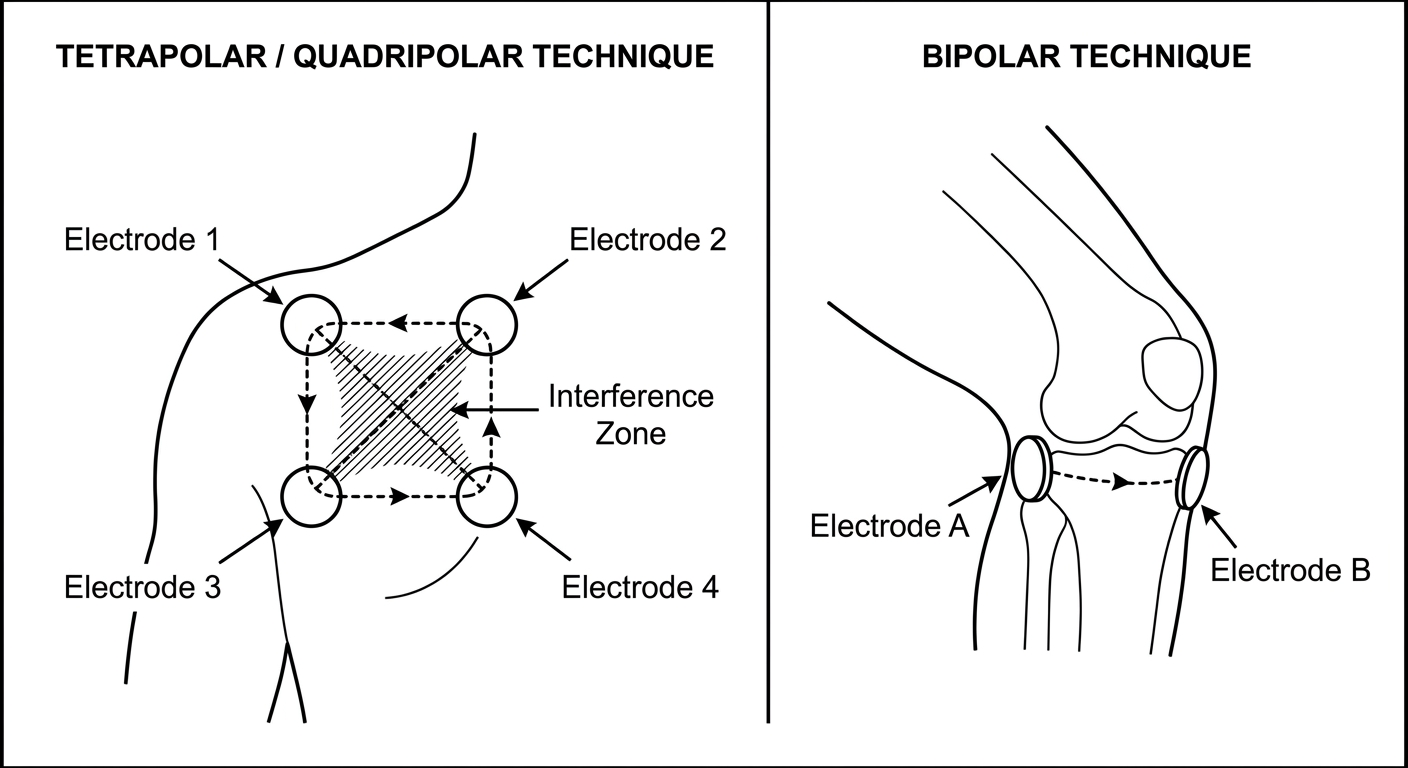
Method 1: Tetrapolar (Quadripolar) Application - TRUE IFT
- Uses 4 electrodes (2 pairs)
- Each pair connected to one circuit
- Electrodes placed so currents cross inside the tissue
- Interference (beat frequency) generated within the body
- Advantage: Precise targeting of deep tissue
E1 ─────────── E2
| INTERFERENCE|
| ZONE |
E3 ─────────── E4
(Circuit A: E1-E3; Circuit B: E2-E4)
Method 2: Bipolar Application - PRE-MODULATED IFT
- Uses only 2 electrodes
- Interference happens inside the machine
- Pre-modulated current delivered to patient
- Simpler setup; suitable for small areas or portable devices
- No physiological difference from tetrapolar (Ozcan et al., 2004)
Method 3: Coplanar Application
- All electrodes on the same surface/plane
- Used when only one side is accessible (e.g., spine)
- Less deep penetration than diagonal placement
Method 4: Diagonal Application
- Electrodes of the two circuits are diagonally opposite
- Maximizes depth of interference zone
- Most commonly used for deep structures
Method 5: Suction Cup Electrode Application
- Electrodes attached via vacuum suction cups
- No adhesives or straps needed
- Allows controlled pressure and better contact
- Patient can be positioned more comfortably
- Useful for contoured areas (shoulder, knee)
Application Procedure - Step by Step
- Explain procedure to patient; obtain consent
- Inspect skin for cuts, rashes, or contraindications
- Position patient comfortably in supported posture
- Clean skin with wet pad/water (not alcohol - dries skin)
- Place electrodes ensuring good contact with skin
- Connect leads - check polarity
- Turn up intensity gradually from zero
- Ask patient for sensation (tingling, buzzing)
- Set AMF, sweep, and timer
- Monitor patient throughout treatment
- Turn intensity to zero before removing electrodes
- Check skin post-treatment
Electrode Placement Examples:
| Region | Tetrapolar Placement |
|---|---|
| Knee | Medial + Lateral surfaces |
| Low Back | Bilateral paraspinal lumbar region |
| Shoulder | Anterior + Posterior |
| Cervical | Bilateral neck + upper trapezius |
TOPIC (f): Describe Different Types of Electrodes (Including Vacuum), Their Effects and Uses (15 Marks)
1. Carbon Rubber Electrodes (Flexible Pad Electrodes)
- Material: Carbon-impregnated silicone rubber
- Sizes: 4x4 cm, 5x5 cm, 8x8 cm (various)
- Use: Most common general purpose electrode
- Effect: Delivers uniform current distribution across contact area
- Application: Must use wet sponge pad or conductive gel underneath
- Advantage: Reusable, durable, easy to place
2. Self-Adhesive Electrodes
- Material: Hydrogel adhesive surface on conductive backing
- Use: Convenient for home therapy and clinical use
- Effect: Good skin contact; conductive gel built-in
- Advantage: No clips or straps needed; single use (hygienic)
- Disadvantage: More expensive; cannot re-use
3. Vacuum / Suction Electrodes (Suction Cup Electrodes)
- Mechanism: Uses negative pressure (vacuum) to hold electrode against skin
- Components: Rubber cup + metal plate + connecting tube to vacuum pump
- Effect:
- Provides mechanical compression in addition to electrical stimulation
- Enhances local circulation via intermittent suction
- Promotes lymphatic drainage
- Ensures firm electrode contact even over irregular surfaces
- Uses:
- Areas with poor electrode contact (shoulder, hip, ankle)
- When patient cannot hold position to keep electrodes in place
- For oedema where combined compression + stimulation is desired
- Contoured or hairy areas
Suction Electrode Diagram
VACUUM PUMP
|
┌────────┴────────┐
│ Suction Cup │
│ (Rubber dome) │
│ ┌──────────┐ │
│ │ Metal │ │
│ │ Electrode│ │ <-- current delivery
│ └──────────┘ │
└─────────────────┘
↓ suction
SKIN SURFACE
4. Water Bath Electrodes
- Mechanism: Patient's limb immersed in water; current conducted through water
- Used for: Hands, feet, wrists, ankles - small irregular surfaces
- Effect: Uniform distribution over entire immersed surface
- Advantage: No direct electrode contact needed; equal distribution
- Precaution: Water temperature must be checked; no breaks in skin
5. Handle Electrodes / Roller Electrodes
- Used for mobile application over larger muscle groups
- Useful for scanning/probing treatment areas
Comparison Table
| Electrode Type | Size | Best For | Special Feature |
|---|---|---|---|
| Carbon Rubber | Various | General use | Durable, reusable |
| Self-Adhesive | Small-medium | Portable/home | Hygienic, convenient |
| Vacuum/Suction | Medium-large | Contoured areas | Adds compression |
| Water Bath | - | Hands/feet | Uniform distribution |
TOPIC (g): Explain Indications, Contraindications, Dangers and Precautions of IFT (15 Marks)
INDICATIONS (Where IFT is Used)
A. Musculoskeletal Conditions
- Osteoarthritis (knee, hip, spine)
- Rheumatoid arthritis (subacute phase)
- Cervical and lumbar spondylosis
- Disc herniation / prolapsed intervertebral disc (PIVD)
- Frozen shoulder (adhesive capsulitis)
- Sports injuries (sprains, strains, muscle tears)
- Tendinitis, bursitis
- Post-fracture rehabilitation
B. Neurological Conditions
- Peripheral nerve injuries (pain management)
- Sciatica
- Bell's palsy (facial palsy)
- Diabetic neuropathy
C. Other Conditions
- Post-surgical pain and swelling
- Urinary incontinence (pelvic floor stimulation)
- Chronic pelvic pain
- Wound healing
- Oedema and lymphoedema management
CONTRAINDICATIONS (Where IFT Must NOT be Used)
Absolute Contraindications
| Contraindication | Reason |
|---|---|
| Cardiac pacemakers | Electrical interference with pacemaker function |
| Malignancy / Active cancer | May stimulate cell proliferation |
| Pregnancy (over abdomen/pelvis) | Risk to fetus; uterine stimulation |
| Active tuberculosis | Risk of spreading infection |
| Deep Vein Thrombosis (DVT) | Risk of dislodging clot (embolism) |
| Thrombophlebitis | Similar risk |
| Areas of haemorrhage/bleeding | May worsen bleeding |
| Over anterior neck/carotid sinus | Risk of cardiac arrhythmia / laryngeal spasm |
Relative Contraindications
- Over open wounds or broken skin
- Areas of impaired sensation (risk of burns due to inability to report discomfort)
- Metal implants at site of application (local heating risk)
- Epilepsy (with caution)
- Febrile conditions
- Over eyes
- Over reproductive organs (gonadal area)
DANGERS OF IFT
- Burns - Due to high current density, poor electrode contact, or electrodes too close together
- Electrolytic burns - Especially with DC component; more with poor skin contact
- Skin irritation - Prolonged application, allergic reaction to electrode gel
- Muscle damage - Excessive intensity causing sustained tetanic contraction
- Spread of infection - If applied over infected wounds
- Cardiac arrhythmia - If applied near the chest or carotid in vulnerable patients
- Venous thromboembolism - If DVT is present and stimulation dislodges clot
PRECAUTIONS
- Always test skin sensation before treatment - patient must report feelings accurately
- Inspect skin for cuts, rashes, dermatitis, metal implants
- Check for contraindications via thorough patient history
- Start intensity from zero and increase gradually
- Never leave patient unattended during treatment
- Electrodes must be flat and in full contact - no edges lifting
- Sponge pads must be evenly wet - dry patches cause uneven current density
- Remove metal jewellery from treatment area
- Check equipment for frayed leads or damaged electrodes before use
- Document treatment parameters (AMF, intensity, duration) for each session
- Reassess skin after each session for redness or burns
- Explain sensations patient will feel (tingling, buzzing) to avoid alarm
Safety Summary Diagram
BEFORE IFT: DURING IFT: AFTER IFT:
- Check contraindications - Monitor intensity - Check skin
- Test skin sensation - Do not leave patient - Document parameters
- Inspect skin - Increase gradually - Give home advice
- Wet sponge pads - Watch for discomfort - Book next session
- Position comfortably - Verify sensation felt
CLINICAL IMAGE: IFT Application on Shoulder

QUICK REVISION TABLE - IFT Key Points
| Parameter | Details |
|---|---|
| Type of current | Medium frequency AC |
| Carrier frequency | 4000 Hz |
| Beat/AMF frequency | 1-250 Hz |
| No. of electrodes | 4 (tetrapolar) or 2 (bipolar) |
| Primary effect | Pain relief |
| Gate control frequency | 50-100 Hz |
| Endorphin release | 2-10 Hz |
| Muscle pump | 1-10 Hz |
| Vasodilation | 100-150 Hz |
| Session duration | 10-30 minutes |
| Course | 6-12 sessions |
Exam Tip: For a 15-mark answer, include: definition, types/classification, mechanism with diagram, all effects in tabular format, clinical relevance, and a well-labelled diagram. Always conclude with clinical significance.