

IMG_20260710_124700627.jpg
Explain by using standard books also
And also explain xray changes and how to see xrays
Reading File
The image shows page 140 of a spine textbook covering Cervical Myelopathy - specifically myotomes, myelopathic signs, special tests, Nurick classification, and radiology (X-ray and MRI findings). Let me search the medical library for comprehensive coverage of all these topics.
Finding Sources
Finding Sources
Reading File
Reading File
Finding Sources
Finding Sources
Reading File
Finding Sources
Finding Sources
Finding Sources
Finding Sources
Reading File
Loading Image
Now I have enough from the standard textbooks. Let me compile a comprehensive, detailed answer.
Cervical Myelopathy - Complete Explanation with Standard Book References
What is Cervical Myelopathy?
Cervical myelopathy is spinal cord compromise due to degenerative change (spondylosis, disc herniation, OPLL) in the cervical spine. It is the commonest cause of spinal cord dysfunction in patients over 55 years of age.
- Bailey and Love's Short Practice of Surgery, 28th Ed.: "Degenerative change in the cervical spine leading to spinal cord compression is the commonest cause of cervical myelopathy in patients over 55 years."
- Campbell's Operative Orthopaedics 15th Ed. 2026: Symptoms are unique and varied - pain is poorly localized; global numbness in upper extremities and difficulty with fine motor coordination are common; gait disturbances may be the first symptom.
I. MYOTOMES (Upper & Lower Limb)
These tell you which nerve root controls which muscle - critical for localizing the level of compression.
Upper Limb Myotomes
| Muscle Action | Root | Clinical Test |
|---|---|---|
| Shoulder abduction | C5 | Deltoid power |
| Elbow flexion | C5, C6 | Biceps curl |
| Elbow extension | C7 | Triceps push |
| Wrist extension | C7 | Cock-up wrist |
| Wrist flexion | C8 | Wrist curl down |
| Finger extension | C7 | Straighten fingers vs resistance |
| Finger flexion | C8 | Grip strength |
| Finger abduction | T1 | Spread fingers apart |
Lower Limb Myotomes
| Muscle Action | Root |
|---|---|
| Hip flexion | L1, L2 |
| Hip extension | L5, S1 |
| Knee flexion | L5, S1 |
| Knee extension | L3, L4 |
| Ankle dorsiflexion | L4 |
| Ankle plantarflexion | S1, S2 |
| 1st metatarsal extension | L5 |
From Campbell's Operative Orthopaedics: "The level of the lesion can be localized by evaluating multiple motor groups, multiple levels of deep tendon reflexes, and sensory abnormalities."
II. CLINICAL SIGNS OF MYELOPATHY
A. Myelopathic Signs (Miller's Review of Orthopaedics, 9th Ed.)
- Weakness of upper and lower limbs - corticospinal tract involvement; lower extremity weakness associated with worse prognosis
- Myelopathic hand - global numbness + difficulty with fine motor coordination (handwriting deterioration, finger clumsiness, difficulty with pinch)
- Loss of manual dexterity - dropping objects, inability to button shirts
- Finger escape sign - fingers kept in extension and adduction; the little finger spontaneously abducts due to weakness of intrinsic muscles (T1 level)
- Grip and release test (+ve) - patient fails to make a fist and release 20 times in 10 seconds (normal = 20 times)
- Loss of proprioception - dorsal column affected → positive Romberg test
B. Upper Motor Neuron Signs (Below the Level of Compression)
| Sign | Explanation |
|---|---|
| Spasticity | Clasp-knife character |
| Inverted radial reflex | Tapping brachioradialis causes finger flexion instead of elbow flexion (C5-C6 level lesion) |
| Hoffmann reflex +ve | Flicking middle finger nail causes thumb flexion |
| Clonus (>3 beats) | Sustained rhythmic contractions of ankle |
| Babinski +ve | Dorsiflexion of great toe on plantar stimulation |
| Bowel and bladder abnormalities | Urinary retention, urgency, or frequency |
| Wide-based spastic myelopathic gait | Ataxia with leg heaviness, inability to tandem walk |
Campbell's Operative Orthopaedics: "Funicular pain - central burning and stinging with or without Lhermitte sign (radiating lightning-like sensations down the back with neck flexion)"
III. SPECIAL CLINICAL TESTS
| Test | How to Perform | Positive Result | Significance |
|---|---|---|---|
| Spurling's sign | Axial compression + lateral flexion toward symptomatic side | Radiating arm pain | Nerve root compression (radiculopathy) |
| Shoulder abduction test | Patient raises arm above head | Symptoms relieved | Nerve root compression - relieves traction on root |
| Lhermitte's sign | Cervical flexion | Electric shock-like sensation radiating down spine | Dorsal column irritation - cord compression |
| Reverse Lhermitte's sign | Cervical extension | Same electric shock sensation | OPLL, epidural compression |
| Upper limb tension tests | Neural stretch maneuvers | Reproduces symptoms | Neural tension in brachial plexus roots |
IV. NURICK CLASSIFICATION OF MYELOPATHY
Based entirely on gait and ambulatory function:
| Grade | Description |
|---|---|
| 0 | Root symptoms only OR completely normal |
| I | Signs of cord compression but normal gait |
| II | Gait difficulties but fully employed |
| III | Gait difficulties that prevent employment, can walk unassisted |
| IV | Unable to walk without assistance |
| V | Wheelchair or bedbound |
Nurick classification is purely functional - it does not assess upper limb function, which is why the modified Japanese Orthopaedic Association (mJOA) score is now preferred in most research.
V. NATURAL HISTORY
From Miller's Review of Orthopaedics:
- Stepwise deterioration then stability - most common (65-80%)
- Slowly progressive decline over months to years - 20-25%
- Rapid decline over days to weeks - 3-5% (most serious)
VI. RADIOLOGY - X-RAY CHANGES IN CERVICAL SPINE
How to Read a Cervical Spine X-Ray - Step by Step
Views to request:
- Lateral view - most important; shows alignment, disc spaces, osteophytes
- AP view - shows disc spaces, vertebral heights, uncovertebral joints
- Oblique views - shows neural foramina (best for radiculopathy)
- Flexion-extension laterals - shows instability (subluxation)
- Open-mouth (odontoid) view - for C1-C2 pathology
Systematic Approach to Cervical X-Ray (ABCS Method)
A - Alignment
- Trace 4 lines on lateral view:
- Anterior vertebral body line (should be smooth curve)
- Posterior vertebral body line
- Spinolaminar line
- Spinous process tips
- Any step-off = subluxation/instability
B - Bones
- Check each vertebral body for height, fractures, density
- Check pedicles on AP view
C - Cartilage (disc spaces)
- Normal cervical disc spaces are roughly equal
- Narrowing = disc degeneration
S - Soft tissues
- Prevertebral soft tissue: >7mm at C2 or >22mm at C6 = abnormal (hematoma, abscess)
X-Ray Changes in Cervical Spondylosis/Myelopathy
As seen on the textbook page image, the key X-ray findings are:
1. Loss of Cervical Lordosis → Straightening or Kyphosis
- Normal: Cervical spine has a gentle lordotic (concave posteriorly) curve
- Spondylosis causes muscle spasm → lordosis is lost → spine becomes straight
- Advanced cases → kyphosis (convex posteriorly = reversed curve)
- Kyphosis worsens cord compression by stretching cord over anterior structures
- How to assess: Draw a line from posterior C2 body to posterior C7 body on lateral X-ray; normal cord hangs 1-3 mm behind this line
2. Kyphosis Angle
- Measured on lateral view
- Progressive kyphosis indicates instability and is a contraindication to laminoplasty
3. Disc Space Narrowing
- Reduced height between vertebral bodies
- Most common at C5-C6 and C6-C7 (highest motion segments)
- Indicates disc degeneration; the disc loses water content (nucleus pulposus desiccation)
4. End Plate Sclerosis
- Increased density (whitening) of the superior and inferior surfaces of vertebral bodies
- Reactive bone formation from repetitive microtrauma
- Indicates chronic degenerative change
5. Osteophyte Formation
- Bony spurs projecting from vertebral body margins
- Anterior osteophytes: large and visible on lateral X-ray, usually do not cause cord compression
- Posterior osteophytes: smaller, project into spinal canal - the dangerous ones that compress cord and nerve roots
- On lateral X-ray: appear as "beaking" or "lipping" at disc-vertebral body junction
6. Facet Arthrosis
- Degenerative changes in the posterior facet joints
- Seen on oblique/lateral views as joint space narrowing, sclerosis, osteophytes
- Contributes to foraminal stenosis → radiculopathy
7. Flexion-Extension Views → Instability
- If one vertebral body slides forward on another during flexion > 3.5 mm or angulation > 11° = pathological instability
- Important before surgery planning
8. Torg Ratio (Pavlov's Ratio) = Spinal Canal Diameter / Mid-Cervical Body Diameter (Lateral X-ray)
- Normal: approximately 1.0
- Canal stenosis: ratio < 0.8
- Miller's Review of Orthopaedics 9th Ed.: "Pavlov (Torg) ratio of less than 0.80 or a sagittal diameter of less than 14 mm are considered risk factors for late neurologic involvement."
- Absolute stenosis: AP canal diameter < 10 mm (severe risk of myelopathy)
- How to measure on X-ray: AP canal diameter is the distance from posterior surface of vertebral body to spinolaminar line; mid-body diameter is the AP width of the vertebral body itself
Summary Table: What to Look For on Cervical X-Ray
| Finding | Where to Look | Significance |
|---|---|---|
| Loss of lordosis / kyphosis | Lateral view - alignment | Early spondylosis; kyphosis = worse prognosis |
| Disc space narrowing | Lateral & AP view between vertebral bodies | Degenerative disc disease |
| End plate sclerosis | Lateral view - vertebral body surfaces | Chronic degeneration |
| Posterior osteophytes | Lateral view - posterior vertebral margins | Canal/foraminal stenosis |
| Facet arthrosis | Oblique/lateral - posterior elements | Foraminal stenosis |
| Torg ratio < 0.8 | Lateral view - canal vs body diameter | Risk of myelopathy |
| Subluxation on flex-ext | Lateral flexion-extension views | Instability |
VII. MRI FINDINGS (from textbook page)
MRI is the gold standard for cervical myelopathy:
- Disc herniation - loss of T2 signal in nucleus (degeneration), bulge or protrusion
- Hypertrophy and buckling of ligamentum flavum - seen posteriorly, especially during extension
- Degree of cord compression - most important MRI assessment
- Cord edema - T2 hyperintensity (bright signal), indicates acute/subacute compression
- Myelomalacia - also T2 bright signal in cord; indicates chronic irreversible cord damage; poor prognostic sign for surgical recovery
- Cervical canal and foraminal stenosis - multi-level involvement common in spondylosis
- Syrinx formation - CSF cavity within cord from chronic compression
- Tandem stenosis - cervical + lumbar canal stenosis together
As shown in the MRI image above from Miller's Review of Orthopaedics: the C3-C4 disc is compressing the cord with high T2 signal within the cord (arrowhead) representing cord ischemia and myelomalacia.
Compression Ratio (on Axial MRI)
$$\text{Compression Ratio} = \frac{\text{Smallest anteroposterior diameter of spinal canal}}{\text{Largest transverse diameter of spinal canal}}$$
A lower ratio indicates greater flattening/compression of the cord.
Quick Clinical Summary
Myelopathy = cord compression → UMN signs below the level + LMN signs at the levelRadiculopathy = root compression → LMN signs in dermatomal/myotomal distributionX-ray shows the bony disease; MRI shows the cord damage - always need both.
Sources: Miller's Review of Orthopaedics 9th Ed., Campbell's Operative Orthopaedics 15th Ed., Bailey and Love's Short Practice of Surgery 28th Ed.
Give xray image with explanation how to identify
Finding Sources
Finding Sources
Reading File
Finding Sources
Reading File
Finding Sources
The THIEME Atlas has an actual plain lateral radiograph image. Let me fetch it along with searching for cervical spondylosis X-ray images from other books.
Loading Image
Finding Sources
That was an MRI, not an X-ray. Let me search more specifically for X-ray images of cervical spondylosis in the textbooks.
Finding Sources
Finding Sources
Finding Sources
Finding Sources
Searching the Web
cervical spondylosis myelopathy xray plain radiograph labeled osteophyte disc narrowing lordosis image
The AAFP article has a good described X-ray image. Let me extract it and also get the Radiopaedia image for a labeled cervical spondylosis X-ray.
Reading Web Page
https://www.aafp.org/afp/2020/1215/p740
Searching the Web
radiopaedia cervical spondylosis plain xray lateral labeled annotated image
I found a Radiopaedia annotated cervical spine X-ray and a Geeky Medics annotated X-ray. Let me fetch these images.
Loading Image
Reading Web Page
https://geekymedics.com/cervical-spine-x-ray-interpretation-…
Now let me fetch the lateral annotated X-ray image and a cervical spondylosis pathological X-ray.
Loading Image
Loading Image
Excellent! I now have everything I need - beautifully annotated X-ray images. Let me now compose a comprehensive, image-rich answer.
Cervical Spine X-Ray: How to Read It + What Changes to Look For
STEP 1: NORMAL ANATOMY - KNOW WHAT YOU'RE LOOKING AT FIRST
This fully labeled lateral cervical X-ray shows all the structures you need to identify:
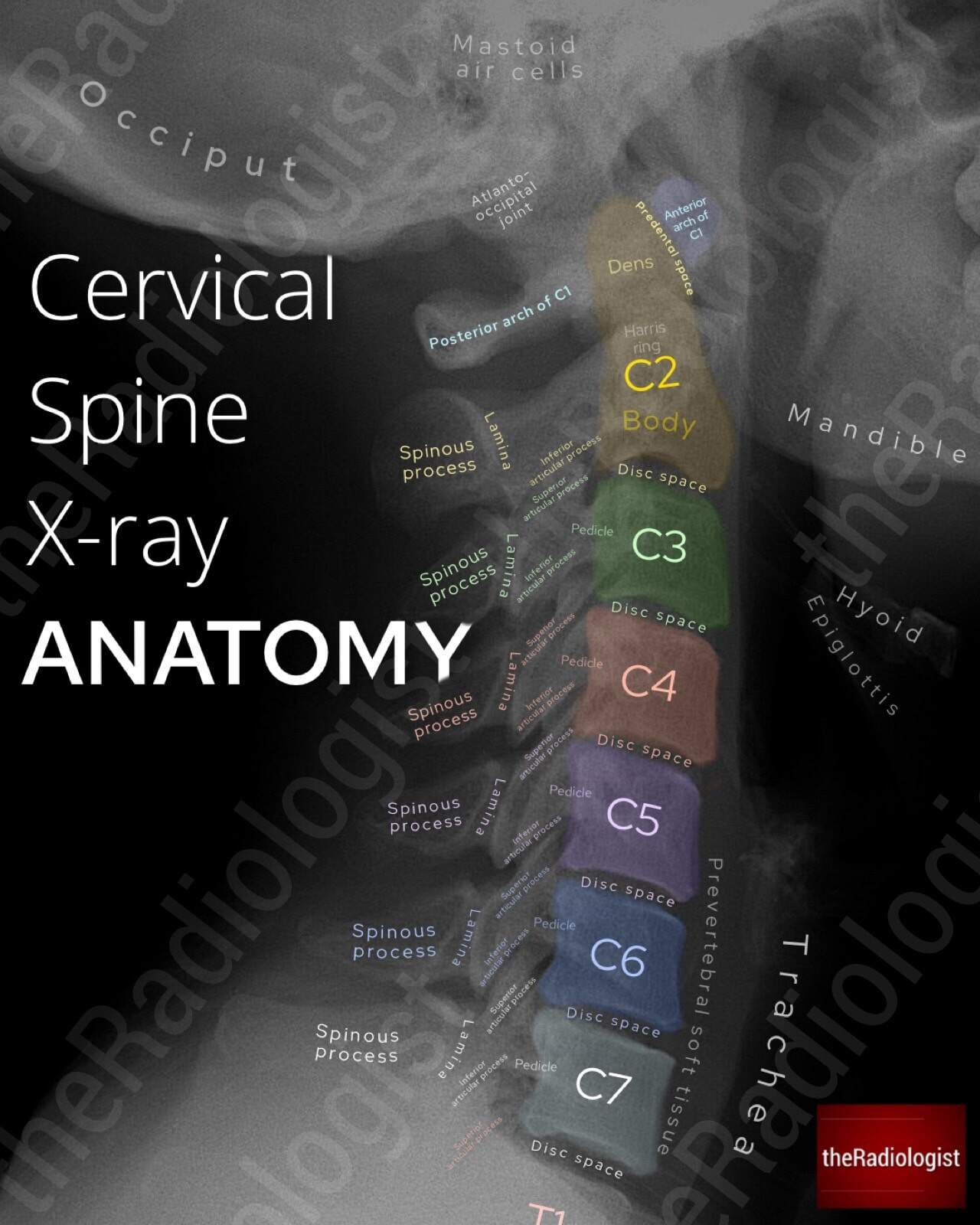
Source: theRadiologist.co.uk - Lateral cervical spine X-ray with color-coded vertebral bodies C2 through C7
What to identify on the Lateral View:
| Structure | How it appears | Location |
|---|---|---|
| Vertebral bodies (C2-C7) | Rectangular grey blocks | Central column |
| Disc spaces | Dark gap between vertebral bodies | Between each level |
| Spinous processes | Bony projections pointing backward | Posterior |
| Laminae | Connect spinous process to body | Posterior arch |
| Pedicles | Connect body to posterior arch | Lateral |
| Facet joints | Overlapping articular surfaces | Posterior to pedicles |
| Prevertebral soft tissue | Grey shadow anterior to bodies | Front of vertebrae |
| Trachea | Dark air column | Anterior |
| Dens (odontoid) | Tooth-like process above C2 body | Top of C2 |
And this is the AP (front) view anatomy:

Source: Radiopaedia - AP cervical spine X-ray showing vertebral bodies, uncinate processes, facet joints
STEP 2: SYSTEMATIC APPROACH - "ABCDS"
Always read X-rays systematically so you miss nothing:
A - Adequacy
- Must see from skull base (occiput) to C7/T1 junction on lateral view
- If C7 not visible, request Swimmer's view
- Check: patient is straight (not rotated) on AP view
B - Bones
- Check each vertebral body height - should be roughly equal
- Look for fractures, loss of height, density changes
- Check posterior elements (spinous processes, pedicles)
C - Cartilage (Disc Spaces)
- All disc spaces should be approximately equal height
- Check each level: C2/3, C3/4, C4/5, C5/6, C6/7
- C5/6 and C6/7 most commonly affected in spondylosis
D - Disc / Degenerative changes
- Osteophytes, end plate sclerosis, facet changes
S - Soft Tissues
- Prevertebral soft tissue:
- Above C4 = should be less than 1/3 of vertebral body width (normal = 7mm at C2)
- Below C4 = should be less than one full vertebral body width (normal = 22mm at C6)
- Widening = hematoma, abscess, fracture
STEP 3: THE 4 ALIGNMENT LINES ON LATERAL VIEW
Draw these 4 imaginary lines - all should be smooth, uninterrupted curves:
LINE 1 (Anterior Vertebral Line) - runs along anterior surface of all bodies
LINE 2 (Posterior Vertebral Line) - runs along posterior surface of all bodies
LINE 3 (Spinolaminar Line) - runs along anterior edge of spinous processes
LINE 4 (Spinous Process Tips) - connects tips of all spinous processes
- Any step-off (>3.5 mm) between adjacent vertebral bodies = subluxation
- Any angulation (>11°) between adjacent levels = instability
- The posterior vertebral line defines the anterior border of the spinal canal - this is the most important line for canal stenosis
Normal Cervical Lordosis:
- The spine should show a gentle concave-backward (lordotic) curve on lateral view
- Measured as C2-C7 Cobb angle = approximately 40° in normal adults
STEP 4: X-RAY CHANGES IN CERVICAL SPONDYLOSIS / MYELOPATHY
Here are the two comparison X-rays showing how to measure C2-C7 lordosis:

Left (A): Straightened cervical spine with lordosis only 3° - note the white arrow pointing to area of disease. Right (B): Post-treatment with restored lordosis of 14° and note "Exostosis" = osteophyte labeled.
Finding 1: Loss of Lordosis / Straightening
- What to look for: The 4 alignment lines lose their normal curve - they become straight or even reverse (kyphosis)
- How to measure: Draw a line along inferior endplate of C2 and another along inferior endplate of C7; measure the Cobb angle between perpendiculars to these lines
- Normal = ~40°; Straightening = <20°; Kyphosis = negative angle
- Clinical significance: Loss of lordosis indicates muscle spasm (early sign) or fixed degenerative deformity. Kyphosis worsens cord compression by stretching the cord over anterior osteophytes
Finding 2: Disc Space Narrowing
- What to look for: Reduced height of the dark gap between vertebral bodies compared to normal levels
- Most common at: C5/6 and C6/7 (highest motion segments)
- Clinical significance: Disc degeneration - loss of nucleus pulposus water content and proteoglycans
- Tip: Compare with the disc space above and below; significant narrowing = at least 50% reduction
Finding 3: End Plate Sclerosis
- What to look for: Increased whiteness (density) of the top and bottom surfaces of vertebral bodies adjacent to the diseased disc
- Clinical significance: Reactive bone formation (eburnation) from chronic mechanical stress
Finding 4: Osteophyte Formation (Spur)
- What to look for: Bony projections ("beaking" or "lipping") from the corners of vertebral bodies
- Anterior osteophytes: Large, visible on lateral X-ray projecting forward - usually not clinically significant for cord
- Posterior osteophytes: Smaller, project backward into the canal - these are the dangerous ones causing cord compression (called "hard disc")
- Uncovertebral osteophytes: Seen on AP view at the lateral margins of vertebral bodies (Luschka joints/uncinate processes), causing foraminal stenosis and radiculopathy
- On the AP view image above, note the uncinate processes - degenerative spurring here narrows the foramen
Finding 5: Facet Joint Arthrosis
- What to look for: On lateral view, the posterior facet joints show loss of joint space, sclerosis (whitening), osteophyte formation
- On the AP view, the facet joints appear as overlapping butterfly-like structures posteriorly
Finding 6: Torg (Pavlov) Ratio < 0.8
- What to look for: On the lateral X-ray, measure the AP diameter of the spinal canal and divide by the AP diameter of the vertebral body at the same level
- How to measure:
- Canal diameter = distance from posterior vertebral body surface → spinolaminar line
- Body diameter = AP width of the vertebral body
- Normal = approximately 1.0
- Canal stenosis = ratio < 0.8
- Absolute stenosis = canal diameter < 10 mm (from Miller's Review of Orthopaedics 9th Ed.)
Finding 7: Instability (Flexion-Extension Views)
- What to look for: Compare lateral X-ray in full flexion vs full extension
- Pathological instability = >3.5 mm translation or >11° angulation at any level
- Clinical significance: Requires surgical stabilization; dynamic compression of cord during motion
STEP 5: SUMMARY CHECKLIST - WHAT TO SAY WHEN REPORTING
When presenting a cervical spine X-ray in OSCE/clinical setting:
"This is a [lateral/AP] view of the cervical spine of a [male/female] patient. The view is [adequate/inadequate]..."Alignment: "There is [normal lordosis / loss of lordosis / straightening / kyphosis] of the cervical spine."Bones: "Vertebral body heights are [maintained / reduced at C_]. No obvious fracture is seen."Disc spaces: "There is disc space narrowing at [C5/6, C6/7]."Degenerative changes: "Anterior and posterior osteophyte formation is seen at [levels]. End plate sclerosis is present. Facet joint degeneration is seen posteriorly."Soft tissue: "Prevertebral soft tissue is [normal / widened]."Impression: "These findings are consistent with cervical spondylosis at [levels], with evidence of [canal stenosis / foraminal stenosis / instability]."
Quick Reference: X-Ray Findings vs What They Mean
| X-ray Finding | What It Means | Significance |
|---|---|---|
| Loss of lordosis | Muscle spasm / early degeneration | First sign of spondylosis |
| Kyphosis | Severe degeneration / post-laminectomy | Worsens myelopathy |
| Disc narrowing | Disc degeneration | Source of instability |
| End plate sclerosis | Chronic mechanical loading | Confirms degeneration |
| Anterior osteophyte | Degenerative response | Usually asymptomatic |
| Posterior osteophyte | Canal stenosis | Causes myelopathy |
| Uncovertebral osteophyte | Foraminal stenosis | Causes radiculopathy |
| Torg ratio < 0.8 | Risk of myelopathy | Even small disc prolapse can cause symptoms |
| Subluxation > 3.5 mm | Instability | Surgical indication |
| Prevertebral widening | Hematoma / abscess / fracture | Emergency - exclude fracture |
Sources: Miller's Review of Orthopaedics 9th Ed., Campbell's Operative Orthopaedics 15th Ed., StatPearls (NCBI), AAFP Cervical Myelopathy Guidelines 2020
Retry
Let me fetch the key X-ray images again so they display properly for you.
Loading Image
Loading Image
Loading Image
All three images loaded. Here is the full explanation:
Cervical Spine X-Ray - How to Read & Identify Changes
IMAGE 1: Normal Lateral X-Ray Anatomy
What to identify on this labeled lateral X-ray (look at it from anterior/front to posterior/back):
| Structure | Location on X-ray | Appearance |
|---|---|---|
| Vertebral bodies C2-C7 | Central column (color-coded) | Rectangular grey-white blocks |
| Disc spaces | Between each vertebral body | Dark (black) gap |
| Dens (odontoid peg) | Top of C2, tooth-shaped | Pointed bony projection upward |
| Anterior arch of C1 | Just anterior to dens | Small oval opacity |
| Predental space | Between anterior C1 arch and dens | Should be < 3 mm in adults |
| Pedicles | Connect body to posterior arch | Oval "eyes" on each side |
| Laminae | Posterior arch | Curved lines behind bodies |
| Spinous processes | Project posteriorly | Bony projections going backward |
| Prevertebral soft tissue | Anterior to all bodies | Grey shadow in front of spine |
| Trachea | Anterior, air column | Dark (black) tube anteriorly |
| Disc space (C5/6, C6/7) | These are the important levels | Most commonly diseased in spondylosis |
IMAGE 2: AP (Front) View Anatomy
On this AP view, identify:
- C6 vertebral body (green) - note the rectangular shape
- Uncinate processes (pink) - small upward projections at lateral edges of vertebral bodies - when these form osteophytes, they narrow the neural foramen and cause radiculopathy
- C5 lamina (yellow) - the posterior arch
- C4/5 facet joint (cyan lines) - when degenerate, shows as sclerosis/narrowing here
- Transverse processes (pink line at edge) - lateral projections
- C2 dens (red outline at top) - check alignment with lateral masses of C1
IMAGE 3: Lordosis Measurement + Osteophyte (Spondylosis X-Ray)
This is the most clinically important image for cervical myelopathy:
Image A (left): Severely straightened cervical spine - C2-C7 lordosis is only 3° (normal ~40°). Note the white arrow pointing to the diseased levels.
Image B (right): Shows C2-C7 lordosis of 14° still reduced but better. Critically - notice the red dotted label "Exostosis" = this is an osteophyte (bony spur), the hallmark of cervical spondylosis. White arrow again marks the problem area.
How to Measure Lordosis (Cobb angle method):
- Draw a line along the inferior end plate of C2
- Draw a line along the inferior end plate of C7
- Draw perpendiculars to each line
- Measure the angle where the perpendiculars intersect
- Normal: ~40°
- Straightening: < 20°
- Kyphosis: negative angle (spine bows forward)
STEP-BY-STEP READING SYSTEM: "ABCDS"
A - Adequacy
- Must see skull base to C7/T1 junction on lateral
- If C7 not visible = request Swimmer's view (arm raised)
- Patient should not be rotated on AP view
B - Bones
- Check every vertebral body height - should be roughly equal
- Look for fracture lines, loss of height, areas of increased whiteness (sclerosis)
- Count vertebrae: C1 (atlas, ring-shaped, no body), C2 (axis, has dens), C3-C7 (typical)
C - Cartilage / Disc Spaces
- Each disc space should be roughly equal height on lateral view
- Most commonly narrowed in spondylosis: C5/6 and C6/7
- Compare each level with the one above and below it
D - Degenerative Changes
Look specifically for:
| Change | How to Identify |
|---|---|
| Loss of lordosis | Alignment lines become straight; measure Cobb angle |
| Kyphosis | Spine bows forward = negative Cobb angle |
| Disc narrowing | Gap between bodies less than adjacent levels |
| End plate sclerosis | Increased whiteness at top/bottom of vertebral body |
| Anterior osteophyte | Bony "beak" projecting forward from vertebral body corner |
| Posterior osteophyte | Bony "beak" projecting backward - dangerous, causes cord compression |
| Facet arthrosis | Loss of facet joint space, whiteness (sclerosis) on lateral view |
| Torg ratio | Canal diameter ÷ body diameter at same level; < 0.8 = stenosis |
S - Soft Tissue
| Level | Normal width |
|---|---|
| Above C4 | < 7 mm (less than 1/3 vertebral body width) |
| Below C4 | < 22 mm (less than one full vertebral body width) |
Widening = hematoma from fracture, abscess, tumor
THE 4 ALIGNMENT LINES (Lateral View)
Draw these 4 lines - all must be smooth, unbroken curves:
ANTERIOR → Line 1: Along FRONT surface of all vertebral bodies
Line 2: Along BACK surface of all vertebral bodies ← most important for canal
Line 3: Along SPINOLAMINAR junction (front edge of spinous processes)
POSTERIOR → Line 4: Tips of all spinous processes
- A step-off > 3.5 mm between adjacent bodies = subluxation (instability)
- Angulation > 11° between adjacent levels = pathological instability
- The space between Line 2 and Line 3 = the spinal canal - measure this for Torg ratio
Summary: X-Ray Findings in Cervical Spondylosis
| Finding | View | Significance |
|---|---|---|
| Loss of lordosis / kyphosis | Lateral | Degeneration; kyphosis worsens myelopathy |
| Disc space narrowing (C5/6, C6/7) | Lateral + AP | Disc degeneration |
| End plate sclerosis | Lateral | Chronic mechanical stress |
| Posterior osteophyte | Lateral | Causes myelopathy |
| Anterior osteophyte (exostosis) | Lateral | Usually asymptomatic |
| Uncinate osteophyte | AP | Causes radiculopathy |
| Facet arthrosis | Lateral/oblique | Foraminal stenosis |
| Torg ratio < 0.8 | Lateral | Risk of cord injury even with minor trauma |
| Subluxation > 3.5 mm on flex-ext | Flexion/extension | Instability - surgical indication |
| Prevertebral widening | Lateral | Fracture / hematoma - EMERGENCY |
Sources: Miller's Review of Orthopaedics 9th Ed., Campbell's Operative Orthopaedics 15th Ed., theRadiologist, Radiopaedia
Treatment non operative and operative with Surgical approaches explain
With images
Finding Sources
Finding Sources
Finding Sources
Finding Sources
Your credits are exhausted. You can purchase a top-up or subscribe to a plan to continue using Orris. If you're already subscribed, your daily credits will reset tomorrow.
This is a shared conversation. Sign in to Orris to start your own chat.