
what is middle ear transformer mechanism. discuss its role in mechanism of sound transmission in detail for 20 marks with diagram and flow charts from Scott Brown, Cummings, stell and marans, Zakir Hussain, dhingra, hazarika and related articles with recent advances according to rguhs university
Reading File
Finding Sources
Finding Sources
Finding Sources
Finding Sources
Finding Sources
Finding Sources
Reading File
Finding Sources
Finding Sources
Reading File
Reading File
Reading File
Reading File
Reading File
Reading File
Searching PubMed
middle ear transformer mechanism sound transmission impedance matching
Loading Image
Loading Image
Reading File
Searching PubMed
middle ear mechanics ossicular chain acoustic impedance
Reading File
Reading File
Reading Article
PMID: 41535176
Loading Image
Searching the Web
middle ear transformer mechanism sound transmission RGUHS ENT 20 marks 2024 2025
Loading Image
Reading File
MIDDLE EAR TRANSFORMER MECHANISM AND SOUND TRANSMISSION
[RGUHS ENT - Long Answer - 20 Marks]
INTRODUCTION
The middle ear is an efficient passive and linear transformer that conducts acoustic energy from the tympanic membrane (TM) to the stapes footplate at the oval window and then to the cochlea. Its fundamental role is to overcome the acoustic impedance mismatch between the air-filled external environment and the fluid-filled cochlea. Without this mechanism, approximately 99.9% of sound energy (about 30 dB) would be reflected at the air-fluid interface.
(Scott-Brown's Otorhinolaryngology H&N Surgery, Vol. 2, p. 619; Shambaugh Surgery of the Ear, p. 491; Cummings Otolaryngology 6e, p. 2466)
PART I: CONCEPT OF ACOUSTIC IMPEDANCE
Acoustic impedance (Z) is the resistance offered by a medium to the propagation of sound waves.
Z = Sound Pressure (P) / Velocity of vibration (v)
- Air: low density, low stiffness, LOW impedance
- Cochlear fluid (perilymph): high density, high stiffness, HIGH impedance
The impedance mismatch ratio between air and fluid predicts that 99.9% of sound energy would be reflected if sound struck the oval window directly. This equals approximately 30 dB of potential energy loss. The outer ear canal adds a further ~9 dB resonance gain. The middle ear transformer mechanism compensates for this loss.
PART II: THE MIDDLE EAR TRANSFORMER MECHANISM
The middle ear acts as an acoustic transformer - it converts large-amplitude, low-pressure sound waves in air into small-amplitude, high-pressure waves in cochlear fluid. This transformation is achieved through four main mechanisms:
MECHANISM 1: AREA RATIO (HYDRAULIC RATIO) - The Most Important
[Diagram from Shambaugh / Cummings - Figure 128.2]
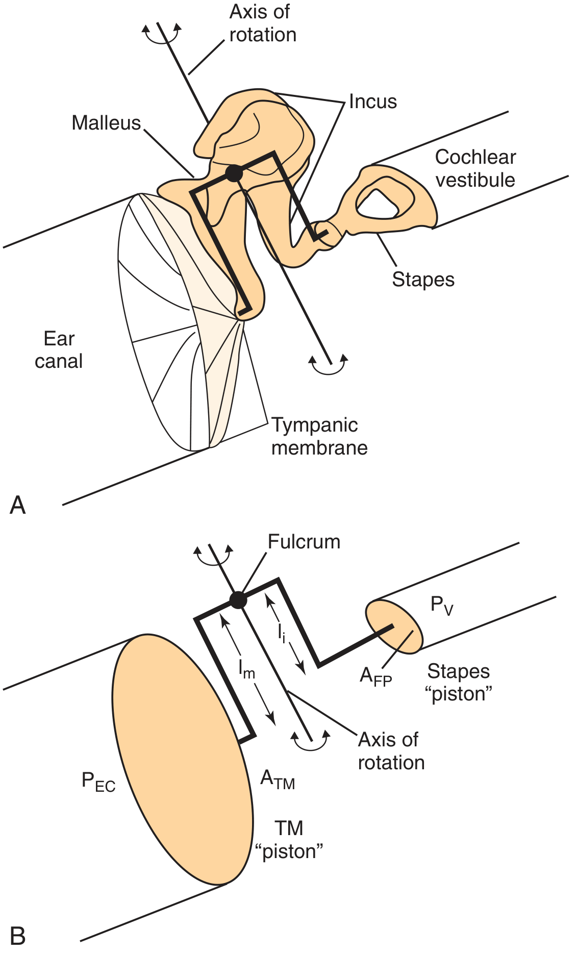
| Parameter | Value |
|---|---|
| Total TM area | 85-90 mm² |
| Effective vibrating TM area | ~55-65 mm² (lower two-thirds) |
| Stapes footplate area | 3.2-3.4 mm² |
| Area ratio | 17:1 to 20:1 |
| Pressure gain | 26 dB |
Principle: The TM collects sound force over its large surface and concentrates it on the tiny stapes footplate. Since Pressure = Force/Area, for the same total force, a smaller area produces proportionally greater pressure.
Pressure at footplate = Pressure at TM × (ATM / AFP) = ~17-20 times increase
(K.J. Lee's Essential Otolaryngology, p. 290; Shambaugh Surgery of the Ear, p. 491)
MECHANISM 2: OSSICULAR LEVER RATIO
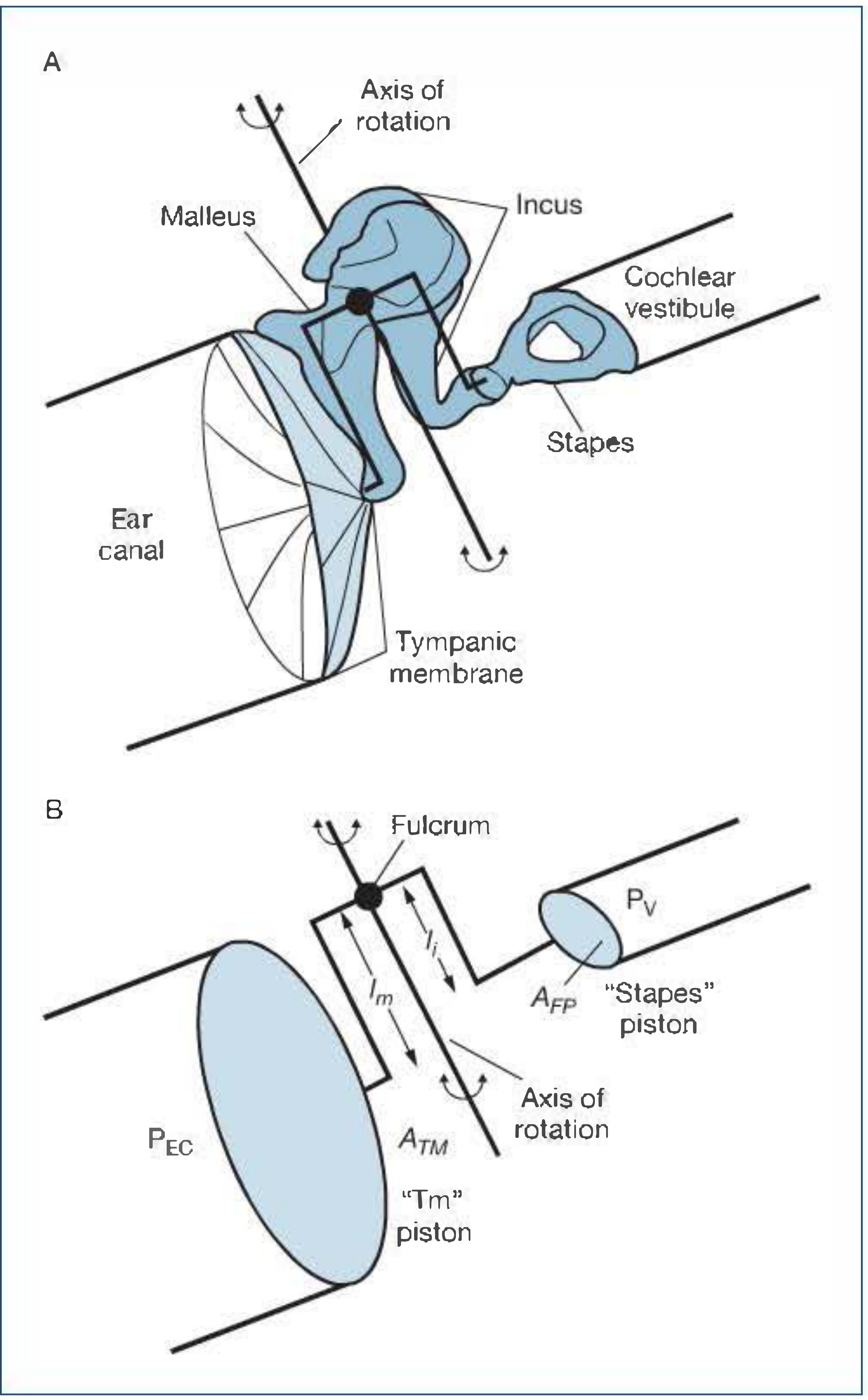
The ossicular chain acts as a class I lever:
- Fulcrum (axis of rotation): Imaginary line joining anterior malleal ligament to the incudal ligament anchoring the short process of incus
- Longer arm (effort arm): Manubrium (handle) of malleus = l_m
- Shorter arm (load arm): Long process of incus = l_i
| Ossicular Lever Parameter | Value |
|---|---|
| Lever ratio (lm / li) | 1.3 : 1 |
| Additional pressure gain | 2 dB |
(Cummings Otolaryngology, p. 2466; Shambaugh, p. 491)
MECHANISM 3: CURVED MEMBRANE (CATENARY) EFFECT
Described by Helmholtz. The TM is not flat but cone-shaped (conical) with the apex (umbo) pointing inward. This curvature:
- Concentrates vibratory energy toward the umbo/manubrium
- Adds an additional mechanical advantage of approximately 2:1 (some authors do not separate this from area ratio in calculations)
- Creates a "catenary lever" effect where the TM acts as a multi-integrated multilever system
Scott-Brown notes: "The middle ear side [of the TM] is multiphasic with significant pressure variations... the structure of the membrane is non-uniform and provides a multiple integrated multilever mechanical advantage."
MECHANISM 4: PHASE DIFFERENCE BETWEEN OVAL AND ROUND WINDOWS
- Under normal conditions, sound reaches the oval window via ossicular coupling and the round window is protected by the intact TM
- This creates a phase difference between the two windows, contributing ~4 dB gain
- This phase difference ensures constructive rather than destructive interference at the cochlear partition
- If TM perforates: both windows exposed simultaneously → phase cancellation → hearing loss
SUMMARY TABLE: TRANSFORMER RATIO CALCULATION
| Mechanism | Ratio | dB Gain |
|---|---|---|
| Area ratio (ATM / AFP) | 17-20 : 1 | ~26 dB |
| Ossicular lever (lm / li) | 1.3 : 1 | ~2 dB |
| Curved membrane / catenary effect | ~2 : 1 | included in area ratio |
| Total Theoretical Gain | ~22 : 1 | ~28 dB |
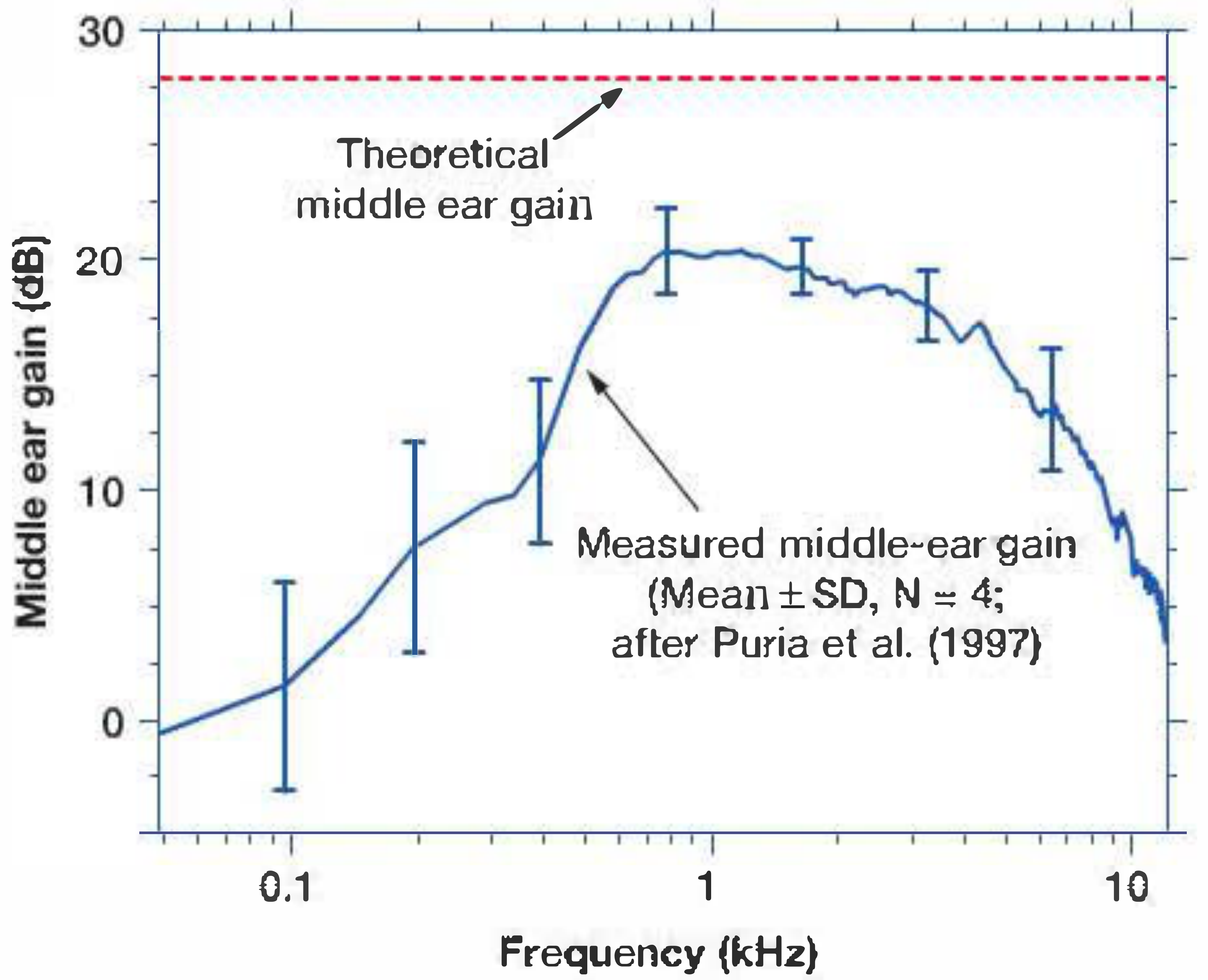
| Actual Measured Gain (Puria et al., 1997) | — | ~20 dB at 1 kHz |
Bekesy's classical calculation: 17 (hydraulic ratio) × 1.3 (lever ratio) = 22 times pressure increase = ~27 dB gain at the oval window.
PART III: DIAGRAM - THE MIDDLE EAR GAIN CURVE
PART IV: FLOW CHART OF SOUND TRANSMISSION
SOUND WAVES (air medium)
|
▼
PINNA (sound collection + directional localization)
|
▼
EXTERNAL AUDITORY CANAL
• Resonance: 2-7 kHz range, adds ~10-15 dB gain
• Funnels sound to TM
|
▼
TYMPANIC MEMBRANE (vibrates)
• Receives low-pressure, large-amplitude waves
• Effective vibrating area: ~55-65 mm²
• At low freq (<1 kHz): uniform vibration of whole TM
• At high freq (>1 kHz): complex multiphasic vibration
|
▼
OSSICULAR CHAIN (Mechanical Coupling)
• MALLEUS: manubrium vibrates with TM → head moves
• INCUS: transmits via incudomalleal joint
• STAPES: long process connects to stapes head
|
▼
TWO TRANSFORMER MECHANISMS:
┌─────────────────────────────────────────────────────┐
│ 1. AREA RATIO (ATM/AFP) │
│ 55 mm² TM : 3.2 mm² footplate = 17:1 │
│ → 26 dB pressure amplification │
│ │
│ 2. OSSICULAR LEVER (lm/li) │
│ Malleus manubrium : Incus long process = 1.3:1 │
│ → 2 dB additional gain │
│ │
│ TOTAL THEORETICAL GAIN: ~28 dB │
│ ACTUAL GAIN: ~20 dB at 1 kHz (frequency-dependent) │
└─────────────────────────────────────────────────────┘
|
▼
STAPES FOOTPLATE at OVAL WINDOW
• High-pressure, small-amplitude piston-like movement
• Footplate area: 3.2 mm²
• Moves in piston-like fashion at low frequencies
|
▼
PERILYMPH (Scala Vestibuli) → TRAVELING WAVE
• Compressional wave in perilymph
• Round window acts as pressure relief valve
• Phase difference (OW vs. RW) = ~4 dB additional gain
|
▼
BASILAR MEMBRANE (Traveling Wave - Bekesy, 1960)
• Base to apex wave propagation
• Tonotopic organization: high freq at base, low at apex
• Maximum displacement = frequency-specific point
|
▼
ORGAN OF CORTI (Mechanotransduction)
• OHCs: active amplification (cochlear amplifier)
• IHCs: shearing of stereocilia → depolarization
• K+ influx → receptor potential
|
▼
SPIRAL GANGLION → AUDITORY NERVE (CN VIII)
|
▼
CENTRAL AUDITORY PATHWAY → AUDITORY CORTEX
(Superior temporal gyrus / Heschl's gyrus)
PART V: ROLE OF INDIVIDUAL MIDDLE EAR STRUCTURES
A. Tympanic Membrane (TM)
Structure and function (Scott-Brown, Vol. 2):
- Consists of pars tensa (three layers: outer squamous, middle fibrous, inner mucosal) and pars flaccida
- Fibrous layer = radial + circular fibres → tension + rigidity
- Conical shape with umbo as apex → catenary lever effect
- At 1-4 kHz: TM reflectance is lowest → maximum energy transmission to cochlea
- Below 1 kHz and above 4 kHz: reflectance rises → less efficient transmission
- Resonant frequency with middle ear: 800 Hz - 1.2 kHz
B. Malleus
- Manubrium embedded in TM fibrous layer
- Head articulates with incus via incudomalleal joint (saddle joint)
- Axis of rotation: anterior malleal ligament → incudal ligament
- Acts as long arm of lever
C. Incus
- Body: articulates with malleus head
- Long process: articulates with stapes head via lenticular process
- Acts as short arm of lever
- Long process perpendicular to manubrium → efficient force transfer
D. Stapes
- Smallest bone in the body (~3 mm)
- Head → anterior and posterior crura → footplate
- Footplate sealed in oval window by annular ligament (stapediovestibular ligament)
- Moves in piston-like fashion at low frequencies
- At high frequencies: rocking motion around long and short axes
E. Middle Ear Muscles and their role in sound protection
Tensor Tympani (V3, medial pterygoid nerve):
- Pulls manubrium medially → increases TM tension
- Activated by: loud sounds, yawning, tactile stimulation of face
- Reflexes in response to self-generated sounds
Stapedius (VII nerve):
- Pulls stapes posteriorly → stiffens annular ligament
- Acoustic stapedial reflex: activated at ~85 dB SPL
- Protective against low-frequency loud noise
- Attenuates low-frequency sounds by 10-15 dB
- Both muscles together: middle ear attenuation reflex (acoustic reflex)
PART VI: FLOW CHART - IMPEDANCE MATCHING IN DETAIL
PROBLEM: Acoustic impedance of air ≪ Acoustic impedance of cochlear fluid
→ Without middle ear: 99.9% energy reflected (~30 dB loss)
SOLUTION: THREE-COMPONENT TRANSFORMER
Component 1: EAC Resonance
EAC resonant frequency = 2.7 kHz
EAC gain = ~9-15 dB (frequency-dependent)
Component 2: TM + Ossicular Transformer
Area ratio gain: ATM/AFP = 17-20:1 = ~26 dB
Lever ratio gain: lm/li = 1.3:1 = ~2 dB
Theoretical gain: = ~28 dB
Actual gain: = ~20 dB
Component 3: Phase protection of RW
Normal ear: RW protected by intact TM
Phase difference (OW-RW): = ~4 dB
NET EFFECT:
At 2 kHz:
Sound pressure loss (air→fluid): = -39.5 dB
EAC gain: = +9.0 dB
Middle ear gain: = +26.6 dB
Total compensation: = +35.6 dB
Net loss at cochlea: ≈ -4 dB (efficient!)
(Scott-Brown's Vol. 2, p. 625)
PART VII: WHY ACTUAL GAIN (20 dB) IS LESS THAN THEORETICAL (28 dB)?
Four reasons (Shambaugh / Cummings):
- TM not a rigid piston: At frequencies >1 kHz, TM breaks into multiple vibrating segments with different phases → effective area decreases
- Energy losses in ossicular joints and ligaments: Force used to stretch ligaments and accelerate ossicular mass → lost before reaching cochlea
- Middle ear air space loading: Compressibility of middle ear air damps TM motion
- Ossicular slippage at high frequencies: Translational movements at rotational axis, especially above 1-2 kHz → reduced stapes motion relative to manubrium
PART VIII: EFFECTS OF PATHOLOGY ON TRANSFORMER MECHANISM
| Condition | Effect on Transformer | Expected Hearing Loss |
|---|---|---|
| Small TM perforation, intact ossicles | Area ratio reduced slightly; RW exposed | 10-15 dB |
| Large TM perforation, intact ossicles | Area ratio markedly reduced; RW exposed → phase cancellation | 40-45 dB |
| Ossicular discontinuity, intact TM | Lever ratio lost; RW protected but no pressure gain | Up to 60 dB |
| Combined (large perforation + ossicular discontinuity) | Both mechanisms lost | 60 dB (max) |
| Otosclerosis (stapes fixation) | Stiffness ↑ → particularly affects low frequencies | 30-60 dB CHL |
| Middle ear effusion | Mass and stiffness ↑ → reduces resonance | 15-40 dB |
(Shambaugh Surgery of the Ear, p. 491-492; Cummings, p. 2466)
PART IX: BONE CONDUCTION - ALTERNATIVE PATHWAY
When middle ear transformer is bypassed, sound can still reach cochlea via:
- Osseotympanic route: TM vibration from bone-conducted energy
- Inertial route: Ossicular chain vibrates due to inertia during skull vibration
- Compressional route: Direct compression of otic capsule
- Inner ear fluid inertia: Perilymph and endolymph inertia during skull vibration
However, without the middle ear transformer mechanism, bone-conducted vibrations of the otic capsule reflect off the stapes footplate due to the acoustic impedance mismatch - this is why BAHA/bone-anchored hearing aids work by bypassing the middle ear entirely.
PART X: RECENT ADVANCES (2021-2026)
1. Finite Element Modeling (FEM) of Middle Ear
Hirabayashi et al. (2022) used combined FEM analysis and audiometry to map how structural changes in the ossicular chain cause conductive hearing loss, revealing frequency-specific patterns of transformer failure. (Front Bioeng Biotechnol, PMID: 36118582)
2. Middle Ear Mechanics and Ossiculoplasty Science (2026)
Norouzi, Guan, and Cheng (2026) published a comprehensive review highlighting how biomechanical understanding of the ossicular transformer mechanism directly guides modern ossiculoplasty technique - including prosthesis design, angulation, cartilage interposition, and contact points. The review emphasizes that restoring the ATM/AFP area ratio and the lever ratio are the two non-negotiable goals of any ossicular reconstruction. (Otolaryngol Clin North Am, PMID: 41535176)
3. Laser Doppler Vibrometry (LDV)
Modern temporal bone studies using LDV have confirmed:
- Frequency-dependent middle ear gain peaks at 800 Hz-1.2 kHz
- TM vibration patterns become markedly non-uniform above 1 kHz
- Stapes footplate rocking motion (vs. pure piston) contributes to frequency selectivity
4. Middle Ear Implants and Active Middle Ear Devices
Understanding of transformer mechanics has led to:
- Totally Implantable Middle Ear Hearing Devices (TIMED) - actuators that directly drive ossicular chain
- Vibrant Soundbridge - floating mass transducer attached to incus or round window
- BONEBRIDGE - transcutaneous bone conduction implants that bypass failed transformers entirely
5. Otosclerosis Mechanics
FEM studies show that stapes fixation primarily destroys the piston-like function of the footplate, but the lever and area ratio mechanisms remain intact - explaining why stapedectomy with prosthesis (restoring only piston motion) can restore near-normal hearing.
PART XI: CLINICAL RELEVANCE - TYMPANOPLASTY PRINCIPLES
The ideal tympanoplasty (Shambaugh):
- Restores sound protection to the round window by creating a closed, air-containing middle ear (addresses phase protection)
- Rebuilds sound pressure transformation by connecting a large TM to the stapes footplate via intact or reconstructed ossicular chain (restores area ratio + lever ratio)
Ossicular Reconstruction Goals:
- PORP (Partial Ossicular Replacement Prosthesis): used when stapes suprastructure intact
- TORP (Total Ossicular Replacement Prosthesis): used when stapes footplate only remains
- Target: air-bone gap ≤20 dB post-operatively
SUMMARY TABLE: KEY NUMBERS TO REMEMBER FOR RGUHS
| Parameter | Value | Source |
|---|---|---|
| Effective TM vibrating area | 55-65 mm² | KJ Lee |
| Stapes footplate area | 3.2 mm² | KJ Lee |
| Area ratio | 17:1 (Bekesy) to 20:1 (Cummings) | Multiple |
| Area ratio gain | ~26 dB | Cummings |
| Ossicular lever ratio | 1.3:1 | All texts |
| Lever ratio gain | ~2 dB | All texts |
| Theoretical transformer gain | 28 dB | All texts |
| Actual measured gain | 20 dB at 1 kHz | Puria 1997 |
| Bekesy's combined ratio | 17 × 1.3 = 22:1 = ~27 dB | Shambaugh |
| Maximum CHL (ossicular discontinuity) | 60 dB | Shambaugh |
| Maximum CHL (large TM perforation) | 40-45 dB | Shambaugh |
| Acoustic stapedial reflex threshold | ~85 dB SPL | Standard |
| Best frequency range of middle ear | 500-3000 Hz (speech frequencies) | KJ Lee |
REFERENCES
- Scott-Brown's Otorhinolaryngology H&N Surgery, Vol. 2 (Gleeson et al., 8th ed.) - Chapter 48: Physiology of the Middle Ear, pp. 619-625
- Shambaugh's Surgery of the Ear (Glasscock-Shambaugh, 6th ed.) - Chapter 3: Physiology of the Middle Ear, pp. 491-492
- Cummings Otolaryngology H&N Surgery (Flint et al., 7th ed.) - Chapter 128: Middle Ear Mechanics and Inner Ear Physiology, pp. 2466-2468
- K.J. Lee's Essential Otolaryngology, 11th ed. - Chapter: Middle Ear, pp. 289-292
- Dhingra's Diseases of Ear, Nose and Throat, 7th ed. - Physiology of Hearing
- Hazarika's Textbook of ENT - Middle Ear Physiology
- Ganong's Review of Medical Physiology, 26th ed. - Sound Transmission, p. 2785-2789
- Norouzi A, Guan X, Cheng YS. Middle Ear Mechanics: The Science of Ossiculoplasty. Otolaryngol Clin North Am. 2026 Apr. PMID: 41535176
- Hirabayashi M, Kurihara S, Ito R. Combined analysis of finite element model and audiometry provides insights into the pathogenesis of conductive hearing loss. Front Bioeng Biotechnol. 2022. PMID: 36118582
- Bekesy G von. Experiments in Hearing. McGraw Hill, 1960 - (Nobel Prize-winning work on traveling wave and middle ear mechanics)
Note for RGUHS exam: The examiner typically expects: (1) definition of acoustic impedance, (2) the three mechanisms - area ratio + lever ratio + curved membrane, (3) Bekesy's calculation (17 × 1.3 = 22:1 = ~27 dB), (4) role of round window, (5) effects of pathology (TM perforation vs. ossicular discontinuity), and (6) a labeled diagram of the tympano-ossicular system. Dhingra and Hazarika both present the "four mechanisms" format used by KJ Lee (area effect, lever action, natural resonance, phase difference) which is the format preferred by RGUHS pattern questions.
This is a shared conversation. Sign in to Orris to start your own chat.