Bone transport indications procedure mechanism complications failures explain in detail with appropriate illustrative diagrams and images
Reading File
Finding Sources
Finding Sources
Searching the Web
bone transport Ilizarov technique indications procedure mechanism complications
Reading File
Reading File
Reading File
Searching PubMed
"bone transport" distraction osteogenesis complications
Reading File
Loading Image
Loading Image
Loading Image
Reading File
Finding Sources
Loading Image
Reading File
Finding Sources
Loading Image
I now have extensive information from Rockwood & Green's (the authoritative orthopaedic textbook) plus excellent illustrative images. Let me compile the comprehensive answer.
Bone Transport: A Comprehensive Guide
Bone transport is a technique based on distraction osteogenesis - the biological process by which new bone is generated between two gradually separated bony surfaces. Pioneered by Gavriil Ilizarov in the 1950s-70s, it remains one of the most powerful tools in orthopaedic surgery for managing large bone defects.
1. BIOLOGICAL MECHANISM - The Foundation
The Tension-Stress Effect (Ilizarov's Principle)
Distraction osteogenesis is the mechanical induction of new bone that occurs between bony surfaces that are gradually pulled apart. Ilizarov described this as "the tension stress effect" - controlled mechanical tension stimulates and maintains the growth and regeneration of living tissues.
Cellular sequence at the distraction zone:
| Phase | Event |
|---|---|
| Corticotomy | Low-energy osteotomy preserving periosteum and medullary vessels |
| Latency (5-7 days) | Hematoma organization, inflammatory response, periosteal activation |
| Distraction | Gradual separation at 1 mm/day (4 × 0.25 mm increments) |
| Consolidation | Mineralization and remodeling of regenerate bone |
Microscopic mechanism: New bone forms in parallel columns extending in both directions from a central growth region - the interzone. Fibroblast-like cells in the interzone elongate along the tension stress vector; collagen fibers align parallel to the distraction direction; these fibroblasts transform into osteoblasts depositing osteoid on the collagen scaffolding, which then mineralizes via direct intramembranous ossification (bypassing the cartilaginous phase of endochondral ossification). A significant neovascularization effect accompanies this, with dense networks of newly formed blood vessels oriented longitudinally.
Source: Rockwood and Green's Fractures in Adults, 10th ed. 2025
2. WHAT IS BONE TRANSPORT?
Bone transport takes distraction osteogenesis a step further: a segment of bone (the transport segment) is cut and slowly moved through a bony defect, pulling new bone (the regenerate) behind it while simultaneously advancing toward the opposite bone end (the docking site).
The sequence:
a) Bone defect present → b) Transport segment cut + external fixator applied + filler (e.g., calcium sulfate antibiotic beads) placed → c) Segment transported at 1 mm/day, new callus forms behind → d) Docking site achieved, frame removed after consolidation
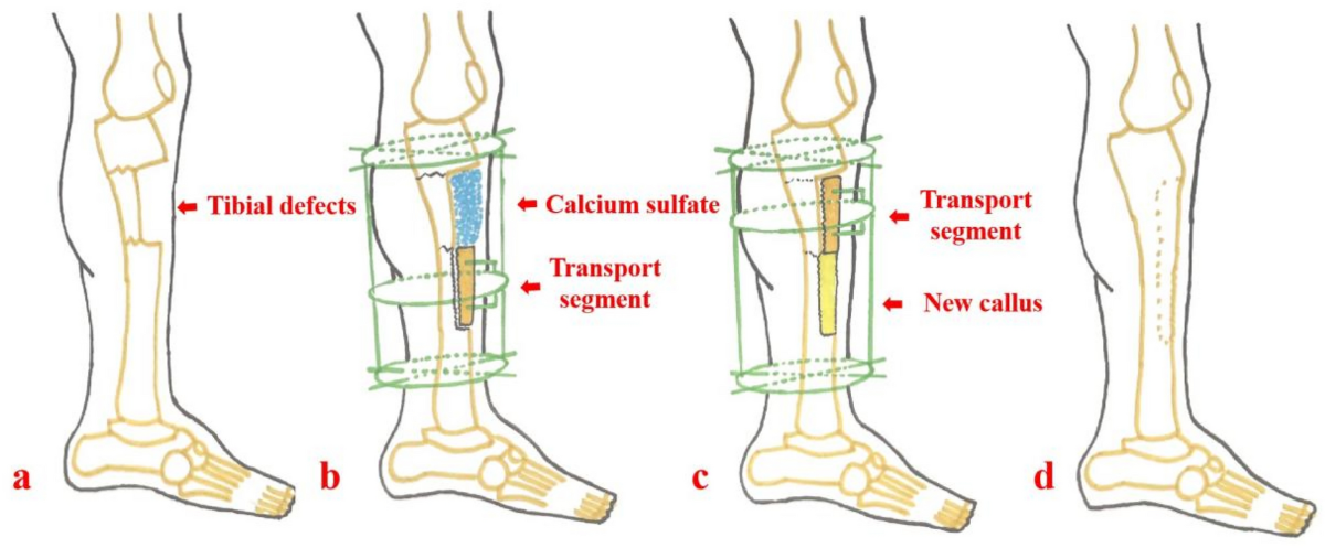
The four stages of bone transport for a tibial defect - from defect (a), to fixator application and transport segment creation (b), to active transport with callus (c), to final healing (d)
3. INDICATIONS
Primary Indications
-
Posttraumatic bone defects - Critical-sized defects (generally >2-3 cm) after open fractures, traumatic bone loss, or following debridement of infected bone. Tibia is the most common site.
-
Chronic osteomyelitis with bone loss - After debridement of infected/necrotic bone leaves a defect. Bone transport is uniquely suited here because the transport process itself stimulates vascular ingrowth, reducing risk of re-infection.
-
Infected nonunion - Failed fracture healing complicated by infection where bone resection is necessary.
-
Tumor resection defects - Following en-bloc resection of bone tumors (especially low-grade), particularly in pediatric patients where prosthetic options are less ideal.
-
Congenital bone deficiencies - Congenital pseudarthrosis of the tibia and other congenital bone defects.
-
Limb-length discrepancy - Combined with deformity correction.
Minimum Defect Size Requiring Transport
| Defect Size | Recommended Approach |
|---|---|
| <2 cm | Acute shortening + compression, bone grafting |
| 2-6 cm | Bone transport or Masquelet technique |
| >6 cm | Bone transport (preferred over Masquelet which needs more graft) |
Contraindications
- Active systemic infection or sepsis
- Severely compromised vascularity (relative - vascular reconstruction may be needed first)
- Non-compliant patient (transport requires daily adjustments for months)
- Severe osteoporosis precluding stable wire/pin fixation
4. PROCEDURE - STEP BY STEP
Frame Options
Bone transport can be performed with:
- Ring (Ilizarov) fixators - most versatile, allow multiplanar correction
- Monolateral fixators with intercalary sliding mechanism
- Taylor Spatial Frame (TSF) / hexapod - computerized 6-axis correction
- Hybrid - external fixation followed by intramedullary nail ("fix and nail" / "rail" technique)
- Intramedullary transport nails - newer generation allowing transport without external frame
Surgical Steps
Step 1 - Debridement (if infection present)
- Radical debridement of all infected and necrotic bone/soft tissue
- Obtain margins of healthy, bleeding bone
- Send deep cultures
Step 2 - Frame Application
- Apply proximal and distal rings/blocks to stable bone segments
- Rings must be parallel to adjacent joints and perpendicular to the bone's mechanical axis
- Hexapod frames allow rings in any orientation with computer-assisted correction
Step 3 - Corticotomy (not osteotomy)
- Low-energy, periosteum-preserving bone cut, typically at the metaphysis (better biology than diaphysis)
- Technique: multiple drill holes + osteotome, or Gigli saw
- The periosteum, medullary vessels, and endosteum are preserved - this is why it differs from osteotomy
- The transport segment is cut to create the intercalary piece that will move
Step 4 - Latency Period (5-10 days)
- Frame locked, no distraction
- Allows hematoma organization and early callus formation
- Longer latency (7-10 days) in elderly, diabetics, smokers, or irradiated bone
Step 5 - Transport Phase
- Rate: 1 mm/day divided into 4 increments of 0.25 mm, 4× daily
- Rhythm: four times daily (more increments = smoother regenerate)
- Patient or family performs adjustments at home
- Radiographs every 2-4 weeks to monitor regenerate quality and transport direction
Step 6 - Docking
- When the transport segment reaches the opposite bone end
- Bone grafting at the docking site is often performed (the docking site is a compressed, scarred junction with poor healing potential)
- Compression across the docking site aids union
Step 7 - Consolidation Phase
- Frame maintained until regenerate bone consolidates (corticalization visible on X-ray)
- Consolidation index: approximately 1-2 months per centimeter transported
- Dynamization (partial unlocking of frame) may be used to stimulate consolidation
Step 8 - Frame Removal
- When radiographs show solid cortical bridging in at least 3 of 4 cortices
- Protected weight-bearing, then progressive loading
"Fix and Nail" Hybrid Technique
A newer approach where rapid bone transport is done with an external fixator, then an intramedullary nail is inserted once transport is complete to reduce time in the frame. This dramatically decreases the external fixation index (months of frame per centimeter corrected), improving patient quality of life.
5. TIMING AND INDICES
Two key numerical indices guide management:
| Index | Definition | Target |
|---|---|---|
| Distraction Index | Months of distraction per cm gained | ~1 month/cm |
| Consolidation Index | Months of frame wear per cm gained | 1-2 months/cm |
| External Fixation Index | Total frame time (months) per cm | <1.5-2 months/cm |
6. COMPLICATIONS - PALEY'S CLASSIFICATION
Dror Paley's classification (widely used) divides complications into:
| Category | Definition |
|---|---|
| Problem | Difficulty during treatment that resolves WITHOUT additional surgery |
| Obstacle | Complication requiring additional surgery but ultimately healing |
| True complication (sequela) | Permanent adverse outcome |
A. Pin/Wire Site Complications
Pin-tract infection - the single most common complication. Checkets-Otterburn grading (from Rockwood & Green):
| Grade | Findings | Treatment |
|---|---|---|
| 1 | Redness, slight discharge | Improved pin care |
| 2 | Redness, discharge, pain, tenderness | Oral antibiotics + pin care |
| 3 | Grade 2, no improvement with antibiotics | Resite pin, continue fixation |
| 4 | Severe soft tissue infection, multiple pins, loosening | Abandon fixation |
| 5 | Grade 4 + radiographic bone changes | Abandon fixation |
| 6 | Post-removal breakdown, sequestrum formation | Curettage |
Wire/pin loosening - causes include osteoporosis, excessive motion, infection; treated by replacing hardware.
B. Regenerate Bone Problems
Premature consolidation ("premature bony union"):
- Most often an incomplete corticotomy rather than true premature healing
- Commonly in tibia: failure to completely osteotomize the posterolateral cortex
- Prevention: manually distract 1-2 mm under fluoroscopy at time of corticotomy
- Treatment: redo corticotomy, accelerated distraction rate, manipulation
Poor regenerate / delayed consolidation:
- Causes: too rapid distraction, poor vascularity, infection, smoking, malnutrition
- Regenerate appears lucent, fractures under load
- Management: slow distraction rate, dynamization, bone stimulators, BMP-2
Regenerate fracture:
- Frame removal too early before adequate consolidation
- Treat with reapplication of frame or cast
C. Docking Site Problems
Docking site non-union - the most technically challenging complication:
- The docking site is a compressed, often scarred/fibrotic junction
- In infected cases, dead or fibrous tissue prevents healing
- Treatment: debridement of docking site + bone graft + bone marrow aspirate concentrate
- Additional compression, possibly exchange nailing
D. Deformity (Axial Deviation) During Transport
- The transport segment drifts off-axis (varus, valgus, procurvatum, recurvatum)
- Incidence: up to 20-30% requiring correction
- Prevention: careful frame alignment, rings perpendicular to bone axis
- Treatment: frame adjustment, strut changes (TSF allows computer-guided correction)
E. Joint Complications
Joint stiffness / contracture:
- Common with adjacent joint immobility during prolonged transport
- Prevention: active physiotherapy throughout treatment
- Most common joints affected: knee (during femoral transport), ankle (tibial transport)
- Major complication: may require Achilles tendon lengthening or arthrolysis
Joint subluxation/dislocation:
- Particularly around the knee during femoral transport
- Prevention: supplemental soft tissue lengthening if needed
F. Neurovascular Complications
Nerve palsy:
- Peroneal nerve palsy is most common with tibial transport (lateral fibular head pin)
- Vascular injury during pin insertion
- Treatment: physiotherapy, nerve decompression if needed
G. Infection-Related
Recurrent osteomyelitis:
- After transport through previously infected zone
- Caused by inadequate initial debridement
- Requires repeat debridement, culture-directed antibiotics, reassessment
H. Hardware Failure
- Wire/pin breakage from fatigue
- Ring cracking
- Strut failure
7. TREATMENT FAILURES
Classification of Failure
Complete failure / amputation:
- Occurs when all reconstruction attempts are exhausted
- Indications: recurrent deep infection, soft tissue failure, patient preference
- Incidence: 5-15% in severe cases (Gustilo IIIB/C)
Partial failures requiring secondary procedures:
- Docking site non-union - bone graft + compression ± exchange nail
- Delayed consolidation - dynamization, bone stimulator (LIPUS, electromagnetic)
- Regenerate insufficiency - slow distraction, BMP, PRP injection
- Infection recurrence - repeat debridement, long-term suppressive antibiotics, hyperbaric O2
Predictors of Failure
| Factor | Impact |
|---|---|
| Smoker | 3× higher complication rate |
| Diabetes | Poor regenerate, infection risk |
| Prior radiation | Very poor biology |
| Gustilo IIIC | High amputation rate |
| Defect >10 cm | Long treatment, high complication burden |
| Poor compliance | Transport errors, premature frame removal |
| Age >60 | Slower consolidation, longer frame time |
ASAMI Score (Association for the Study and Application of Ilizarov Methods)
Used to grade outcomes after bone transport:
Bone results:
- Excellent: union, no infection, deformity <7°, limb-length discrepancy (LLD) <2.5 cm
- Good: union + 1 of above criteria
- Fair: union + 2 of above criteria
- Poor: non-union, re-fracture, or >3 criteria
Functional results:
- Excellent: active, no limp, no pain, full ROM
- Good: 1 criterion not met
- Fair: 2 criteria not met
- Poor: 3 criteria not met
8. MODERN ADVANCES
Intramedullary Transport Nail
- Fully internal devices (e.g., FITBONE, PRECICE) that allow bone transport without external fixation
- Eliminates pin-tract infections and frame cumbersomeness
- Activated via external magnetic remote controller
- Currently gaining wider adoption for select cases
Bone Transport Over an Intramedullary Nail ("BON")
- External fixator performs transport while a nail maintains alignment
- Reduces axial deviation
- Shorter external fixation time
Masquelet (Induced Membrane) Technique - Comparison
- Stage 1: cement spacer placed in defect to induce biological membrane
- Stage 2 (6-8 weeks): spacer removed, defect packed with bone graft inside the membrane
- Advantages over bone transport: shorter treatment time, no external frame
- Disadvantages: needs large quantities of graft for big defects (>6 cm), soft tissue still required
3D Printing + Ilizarov
- 3D-printed antibiotic bone cement prosthetics combined with Ilizarov frame
- Controls local infection while maintaining length
Summary Table
| Aspect | Key Points |
|---|---|
| Principle | Tension-stress → intramembranous ossification in distraction gap |
| Rate | 1 mm/day (0.25 mm × 4 daily) |
| Latency | 5-10 days before starting distraction |
| Frame time | ~1-2 months/cm transported |
| Indications | Bone defects >2-3 cm, infected nonunion, osteomyelitis, tumor resection |
| Main complications | Pin infection, axial deviation, docking site non-union, joint stiffness |
| Failure rate | 5-15% requiring amputation in severe cases |
| Key advantage | Fully autologous, infection-resistant, simultaneous soft tissue expansion |
| Key disadvantage | Prolonged treatment, high patient burden, multiple complications possible |
References:
- Rockwood and Green's Fractures in Adults, 10th ed. 2025 - "Biology of Distraction Osteogenesis" and "Bone Transport" sections
- Campbell's Operative Orthopaedics, 15th ed. 2026 - Distraction osteogenesis technique and complications
- Advances in Bone Transport Techniques - PMC - Ilizarov vs. Masquelet comparison
- Ilizarov Bone Transport for Distal Tibial Defects - Dove Press
Bridge plating principle usage indications methodology and rules to follow failure explain in detail with appropriate illustrative diagrams and images
Reading File
Finding Sources
Finding Sources
Searching the Web
bridge plating principle indications technique rules orthopaedic fracture fixation
Reading File
Finding Sources
Finding Sources
Loading Image
Loading Image
Reading File
Finding Sources
Loading Image
Loading Image
Reading File
Reading File
Loading Image
Reading File
Reading File
Loading Image
Loading Image
Loading Image
Finding Sources
I now have all the content and images needed. Let me compile the comprehensive, detailed answer.
Bridge Plating: Principle, Usage, Indications, Methodology, Rules, and Failures
1. THE CORE PRINCIPLE
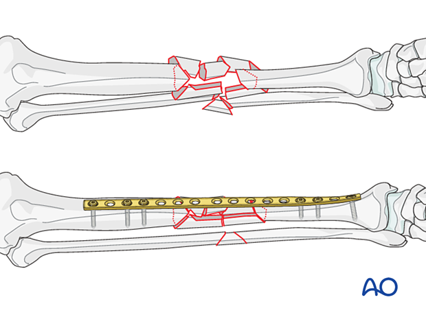
Bridge plating is a method of internal fixation in which a plate is used as an internal splint - spanning ("bridging") a comminuted or multifragmentary fracture zone without attempting to reduce, compress, or directly fix the individual fracture fragments within that zone.
The defining conceptual shift from other plating modes:
| Feature | Compression / Lag Plating | Bridge Plating |
|---|---|---|
| Goal | Anatomic reduction + absolute stability | Length + alignment + rotation + relative stability |
| Fracture handled | Simple (2-part) | Comminuted / multifragmentary |
| Stability type | Absolute | Relative |
| Expected healing | Primary (direct) bone healing, no callus | Secondary bone healing with callus |
| Fracture site handling | Directly reduced and fixed | Left undisturbed - "biologically protected" |
| Periosteal stripping | Occurs at fracture site | Avoided - minimal to zero |
"Bridge plating is most commonly utilized to span comminuted metaphyseal and diaphyseal fractures. Rather than striving for anatomic reduction and compression of individual fracture fragments, the comminuted region is simply bridged. The resultant construct provides relative rather than absolute stability."
- Rockwood and Green's Fractures in Adults, 10th ed. 2025
Why Relative Stability Promotes Healing in Comminuted Fractures
In a comminuted fracture, each fragment has its own periosteal and soft tissue blood supply. Stripping these attachments to achieve anatomic reduction devascularizes the fragments and invites non-union, infection, and avascular necrosis. Bridge plating preserves the fracture biology - the fragments remain attached to their blood supply, and controlled micromotion at the fracture site stimulates callus formation via the interfragmentary strain mechanism. Callus is the appropriate healing response for this mechanical environment.
The plate acts as an "internal fixator" - conceptually similar to an external fixator but implanted.
2. INDICATIONS
Strong Indications
- Comminuted diaphyseal fractures (3+ fragments) - tibia, femur, humerus, forearm
- Multifragmentary metaphyseal fractures - distal femur, proximal tibia, proximal humerus
- Segmental fractures - two fracture lines with an intermediate bone segment
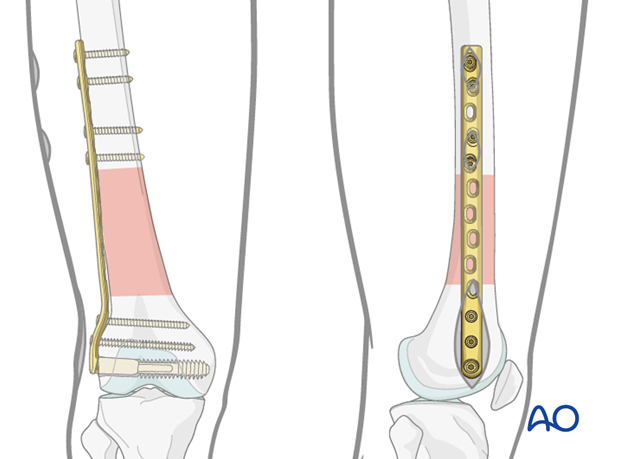
- Highly comminuted periarticular fractures - where the meta-diaphyseal zone is shattered even when the articular block is reconstructed with absolute stability
- Open fractures with bone comminution where soft tissue coverage is difficult (especially with MIPO technique)
- Periprosthetic fractures around hip or knee arthroplasty with comminution (Vancouver B and C)
- Pathological fractures with comminution around tumor/metastatic lesions
- Situations where the overlying soft tissues preclude direct access to the fracture zone
Hybrid Fixation - The Combined Approach
For periarticular fractures, a hybrid construct is the gold standard:
- Absolute stability (lag screws / direct reduction) for the articular block - because joint surfaces require anatomic reduction
- Bridge plating (relative stability) for the meta-diaphyseal comminution - preserving biology in the shattered shaft region
Contraindications
- Simple (2-part) transverse or oblique fractures where anatomic reduction and compression are achievable - bridge plating here would leave a biomechanically unfavorable gap
- Active deep infection at the site (relative)
- When intramedullary nailing is clearly superior and safer (most femoral and tibial shaft fractures)
3. BIOMECHANICAL MECHANISM
How the Plate Works as an Internal Splint
The plate is fixed to the intact proximal and intact distal bone segments with screws, while the comminuted middle is untouched. Mechanically:
- The plate absorbs and distributes bending, torsional, and axial loads across the fracture zone
- It maintains length (prevents telescoping), alignment (prevents angulation), and rotation (prevents malrotation)
- It allows controlled micromotion at the comminuted zone - this is not a flaw but a design feature that drives callus formation
The Working Length Concept (Critical)
Working length (WL) = the distance between the most distal screw in the proximal segment and the most proximal screw in the distal segment. It is the unsupported length of plate spanning the fracture gap.
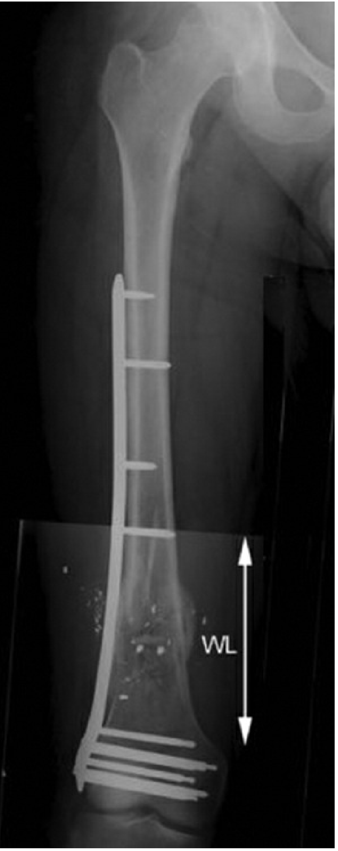
Key relationship: Fracture stability is INVERSELY proportional to working length
- Longer WL = more flexibility = more micromotion = more callus stimulus (good for biology, but risks mechanical failure)
- Shorter WL = stiffer construct = less micromotion = may inhibit callus (too stiff) but stronger mechanically
"Working length is determined both by the fracture pattern and by the surgeon and the way a surgical implant is applied." - Rockwood and Green's, 10th ed.
For large zones of comminution: screws should be placed near the fracture gap to reduce working length and keep plate strain lower.
For short zones of comminution (3 or fewer plate holes): screws should be placed further from the fracture to allow a longer working length - this optimizes mechanobiology (more micromotion stimulus).
Fixation Span vs. Working Length (Distinction)
These two are often confused but are different:
| Term | Definition | Effect of Increase |
|---|---|---|
| Working length (bridge span) | Distance between the two screws closest to the fracture | Decreases stiffness; increases micromotion |
| Fixation span | Maximum distance between the outermost screws on one side | Increases construct strength; reduces stress at end screw |
4. PLATE SELECTION FOR BRIDGE PLATING
Plate Types Used
Locking Compression Plate (LCP) - Most Commonly Used
- Combination holes accept both cortical (conventional) and locking screws
- Locking screws thread into the plate head - the plate does NOT need to contact bone (no periosteal compression)
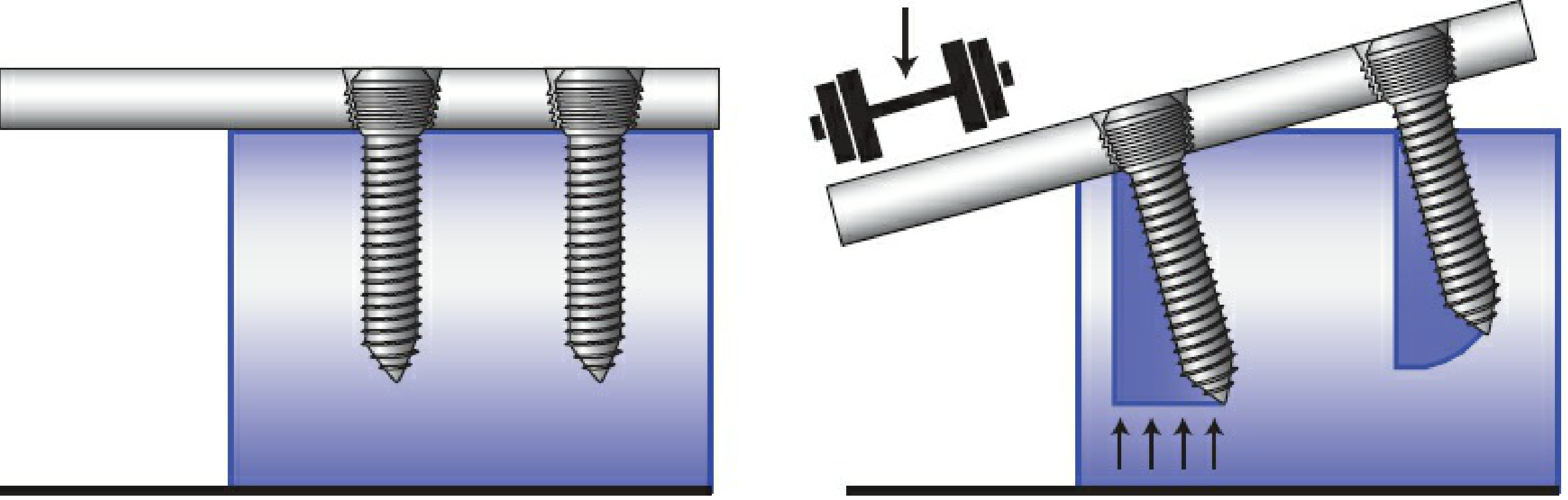
- Behaves as a fixed-angle device - all locking screws fail simultaneously (not sequentially like conventional screws)
- Ideal for bridge mode especially in osteoporotic bone and short metaphyseal segments
Less Invasive Stabilization System (LISS)
- Early generation of purpose-built bridge plate
- Unicortical self-drilling locking screws
- Percutaneous insertion jig
- First designed specifically for minimally invasive bridge plating of distal femur and proximal tibia
Conventional (DCP / LC-DCP) Plates
- Can be used in bridge mode but require bone contact (compresses periosteum)
- Less ideal biologically for long bridge spans
- Used when locking plates unavailable or in good bone stock
Locking vs. Conventional Screw Failure Modes
5. METHODOLOGY - SURGICAL TECHNIQUE
Pre-operative Planning
- Study X-rays: identify the fracture pattern, length of comminuted zone, bone quality
- Template the plate: plate should be at least 2-3x the length of the fracture zone
- Plan screw positions: minimum 3 screws (6 cortices) on each side of the fracture
- Plan the approach: direct open vs. MIPO (minimally invasive plate osteosynthesis)
- Obtain contralateral limb X-rays for length and rotational reference
The MIPO Approach (Preferred for Biologic Reasons)
MIPO is the ideal technique for bridge plating. Rather than making a long incision over the entire fracture, the plate is inserted through small stab incisions at each end, tunneled submuscularly (epiperiosteally) beneath the muscles.

Advantages of MIPO:
- Zero periosteal stripping at the fracture zone
- Preserves soft tissue attachments to all fragments
- Dramatically reduces infection risk in open fractures
- Faster union due to preserved biology
Step-by-Step Surgical Procedure
Step 1 - Patient positioning and fracture table
- For femur: fracture table with traction allows indirect reduction by ligamentotaxis
- For tibia: supine with leg free
- Image intensifier available throughout
Step 2 - Indirect reduction
- Apply traction to restore length
- Use femoral distractors, external fixators temporarily, or reduction forceps on proximal/distal segments only
- Check length on image intensifier - compare to contralateral side
- Check alignment (varus/valgus/procurvatum/recurvatum) in both planes
- Check rotation clinically (foot profile, lesser trochanter symmetry, cortical step sign)
- Never directly handle or strip the fracture fragments
Step 3 - Plate contouring
- Pre-bend the plate to match the expected bone surface (especially important at metaphysis)
- Slight over-contouring for diaphyseal application (to prevent a gap on the opposite cortex when the plate is tightened)
- If using anatomically pre-contoured plates (LCP distal femur, proximal tibia), contouring may be minimal
Step 4 - Plate insertion (MIPO)
- Make a limited incision proximally (5-8 cm) and distally (3-5 cm)
- Create a submuscular tunnel by blunt dissection along the bone surface using fingers or a soft tissue protector
- Slide the plate through the tunnel
- Check position under image intensifier in both planes: plate must be centered, not too anterior or posterior
Step 5 - Temporary fixation
- Use K-wires through plate holes to temporarily hold the plate to bone at each end
- Confirm alignment, length, and rotation before permanent screws
- Rotational check: compare lesser trochanter appearance bilaterally (femur), ankle position (tibia)
Step 6 - Definitive screw insertion
- First screw: most proximal hole
- Second screw: most distal hole
- Re-check alignment and length
- Add additional screws: minimum 3 bicortical screws (6 cortices) on each side
- Leave the fracture zone holes empty - this is mandatory for bridge plating
- For locking screws: drill guide must be perpendicular to the plate (angulation of even 5-10° reduces locking stability by 37-69%)
Step 7 - Final checks
- Intraoperative fluoroscopy: AP and lateral of both ends and the fracture zone
- Confirm no screw in the wrong fragment or blocking the fracture
- Check plate is flush (not proud) to the bone surface
6. THE RULES OF BRIDGE PLATING
These are the key technical rules derived from biomechanical principles and clinical evidence:
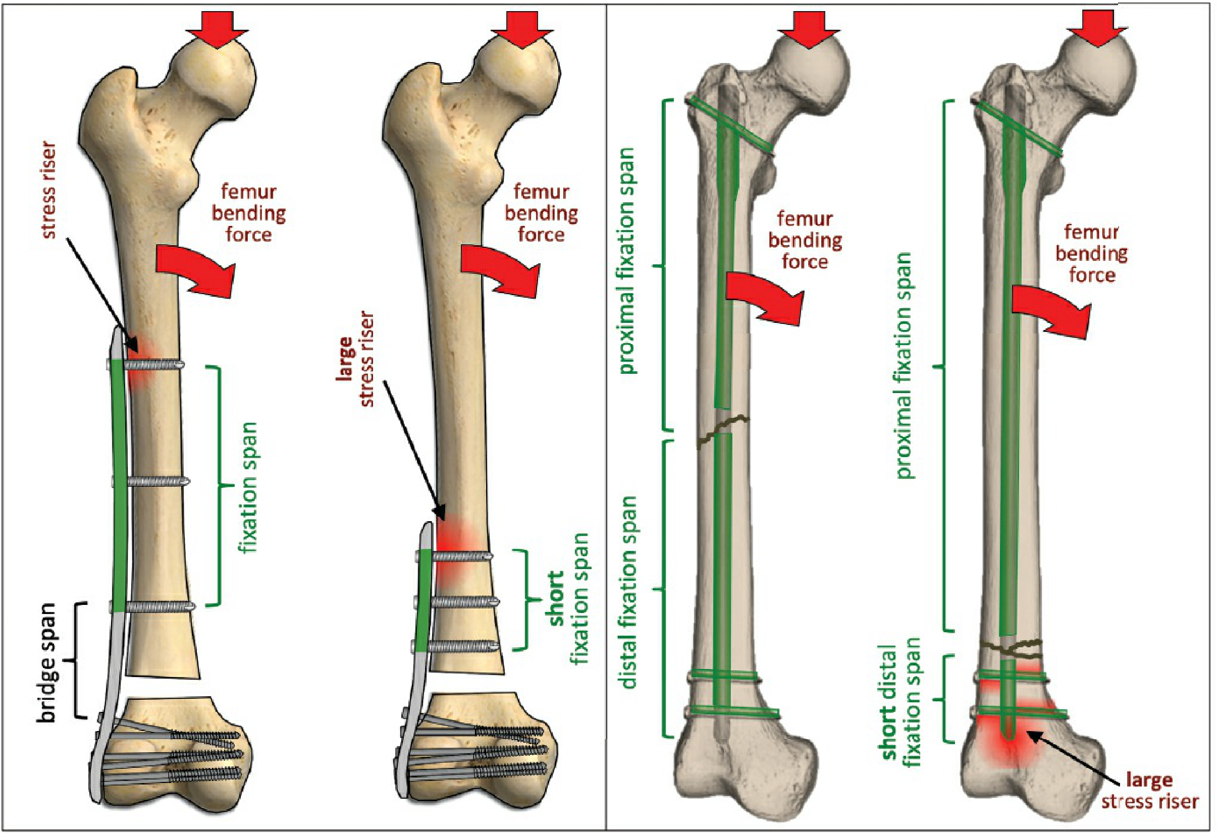
Rule 1: Use a LONG Plate
"Many surgeons emphasize the importance of a long plate with judiciously placed screws." - Rockwood and Green's
The plate should be significantly longer than the fracture zone. General guideline: plate length ≥ 2-3× the fracture zone length. A long plate:
- Increases the fixation span (more mechanical advantage)
- Reduces stress concentration at the end screws
- Allows wider screw spacing for better biomechanics
Rule 2: Do NOT Fill Every Hole
This is one of the most misunderstood rules. Empty holes near the fracture are intentional and beneficial:
- They create working length (micromotion for callus)
- Plate strain data shows that holes 5 or more positions away from the fracture gap have negligible strain regardless of screw placement
- Filling every hole creates a construct that is too stiff for secondary bone healing
"Not all holes of the plate need to be filled with screws to provide similar fixation stiffness." - Rockwood and Green's
However, the holes closest to the fracture edge should have screws to control the bridge span and prevent excessive plate bending.
Rule 3: Minimum 3 Screws (6 Cortices) on Each Side
- Minimum 3 bicortical screws (= 6 cortical purchase points) on each side of the fracture
- Beyond 4 screws per side, additional screws add marginal benefit in normal bone
- In osteoporotic bone: more screws + locking screws required
- The outermost and innermost screws have the greatest biomechanical contribution; middle screws add marginally less
Rule 4: Spread the Screws - Maximize Fixation Span
Screws within a given segment should be spread as far apart as possible:
- Maximizes fixation span
- Reduces stress concentration at the end screw (stress riser)
- One screw near the fracture edge + one screw at the far end of the plate = maximum mechanical advantage
Rule 5: NEVER Directly Reduce or Strip the Comminuted Zone
- No elevating periosteum off the individual fragments
- No clearing hematoma from between fragments
- Indirect reduction only - traction, ligamentotaxis, distractor
- Violation of this rule converts a biologically favorable bridge construct into a devascularized zone prone to non-union
Rule 6: Restore Length, Alignment, and Rotation
The three surgical goals that must be verified before final screw insertion:
- Length: Compare to contralateral limb or preoperative templating
- Alignment: AP and lateral fluoroscopy - no varus/valgus/recurvatum/procurvatum
- Rotation: Clinical assessment (foot profile, lesser trochanter, cortical step sign)
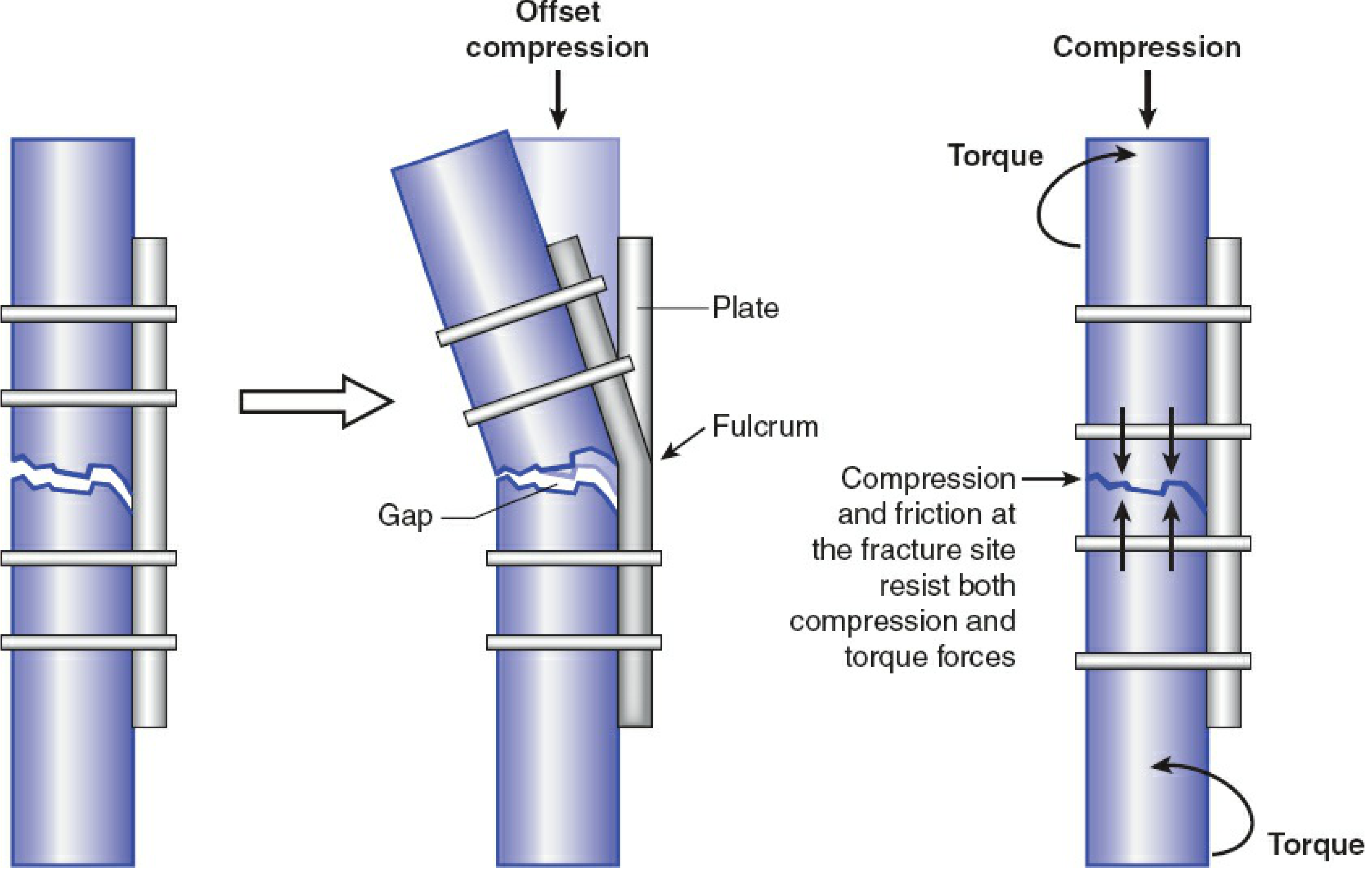
Rule 7: Correct Plate Contouring
- Plate must match the bone surface contour
- A flat plate applied to a curved bone and tightened will cause a gap on the opposite cortex - creating a fulcrum for plate bending failure
- Over-contouring in the mid-diaphysis creates an initial gap between the plate and bone, which closes when the plate is tightened - resulting in compression on the opposite cortex
Rule 8: Screw Density Rule (Plate-Screw Ratio)
The plate-screw ratio is the number of screws used divided by the total number of plate holes.
- Optimal ratio: 0.4-0.5 (fill only 40-50% of holes)
- Too high (>0.7): construct too stiff, inhibits callus
- Too low (<0.3): inadequate purchase, risk of failure
- This ratio concept is specific to locking plates in bridge mode
7. PLATE FAILURE - Mechanisms and Prevention
The Core Mechanism of Bridge Plate Failure
Plates are most susceptible to bending failure because they are thin, are offset from the bone's neutral axis, and have low moments of inertia.
In bridge mode, if a gap exists on the cortex opposite the plate, the fracture site acts as a fulcrum. Under axial loads (body weight), the plate bends repeatedly at the fracture edges - this is cyclic fatigue loading.
Failure Through a Screw Hole (Stress Riser Failure)
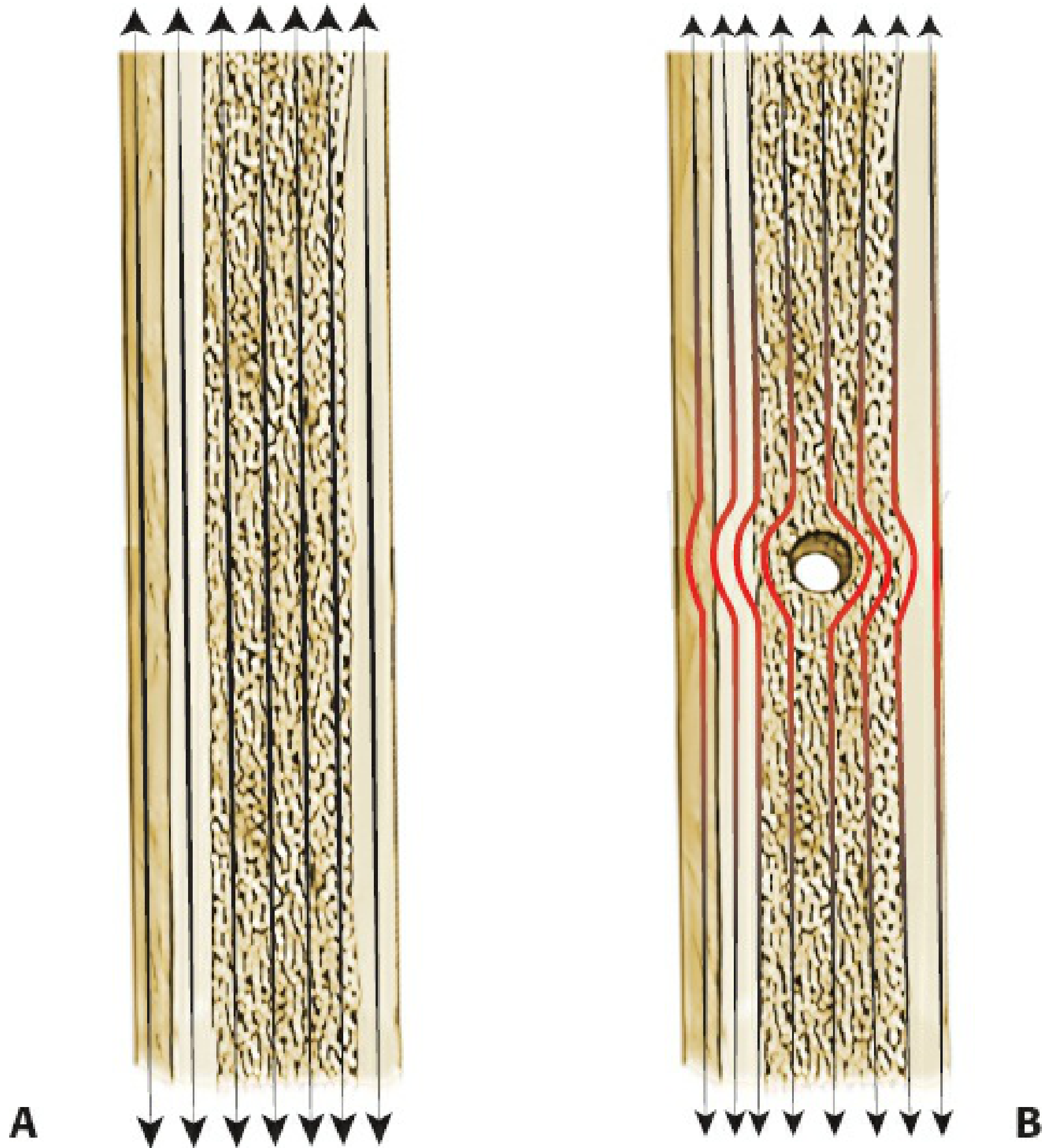
Stress is maximally concentrated at the two plate holes adjacent to the fracture gap (plate-bone interface), regardless of where screws are placed. This is where fatigue fracture of the plate occurs.
Causes of Bridge Plate Failure
| Cause | Mechanism | Prevention |
|---|---|---|
| Plate too short | High stress at end screws; inadequate fixation span | Use a plate ≥ 2-3× fracture zone length |
| Too few screws / cortices | Insufficient purchase; screw pullout | Minimum 3 screws (6 cortices) per side |
| All holes filled | Over-stiff construct; stress concentration at fracture edge | Leave fracture-zone holes empty; maintain working length |
| Poor plate contouring | Gap on opposite cortex → fulcrum → plate bending | Pre-contour; slight over-contouring for diaphysis |
| Plate on compression side | Under loading, a gap opens at the fracture → fulcrum | Place plate on tension side of bone where possible |
| Premature weight-bearing | Excessive cyclic load before callus consolidation | Strict weight-bearing restrictions until callus visible |
| Failure to achieve callus | Non-union → indefinite cyclic loading → metal fatigue | Ensure biology is preserved; assess union at 6-8 weeks |
| Locking screw angulation | Incomplete thread engagement; reduced bending stability by 37-69% | Use drill guide perpendicular to plate |
| Unicortical locking screws in torsion | Substantially lower torsional resistance than bicortical | Prefer bicortical screws; unicortical only where anatomy mandates |
The Most Critical Point: Non-union = Inevitable Plate Failure
Bridge plates are designed as temporary splints until biological healing (callus formation) occurs. Once callus bridges the fracture, the bone assumes its own load and the plate stress drops dramatically. If non-union occurs, the plate continues to carry all loads indefinitely, leading to cyclic fatigue failure - typically at the fracture edge hole.
"Plates are most susceptible to bending failure... If a gap is left on the side opposite the plate, as when a bridge plating technique is used... the fracture site can become a fulcrum around which the plate bends under combined compressive and bending loads." - Rockwood and Green's, 10th ed.
Plate Failure Through a Screw Hole
When a plate breaks at a screw hole adjacent to the fracture, it means:
- The fracture has not healed (non-union) - most common cause
- Excessive working length (screws placed too far from fracture edge with large comminuted gap)
- The construct has been under cyclic fatigue loading without bone healing sharing the load
"Plate strains are highest at the two holes adjacent to the fracture gap... For large zones of comminution, screws should be placed near the fracture gap and spread over a long plate length to reduce strains in the plate." - Rockwood and Green's
8. COMPLICATIONS
Construct-Level
| Complication | Description | Management |
|---|---|---|
| Plate breakage | Fatigue fracture at screw hole adjacent to fracture | Revision with longer plate + bone graft if non-union |
| Screw loosening | Loss of purchase, especially in osteoporosis | Re-fixation with locking screws, augmentation |
| Non-union | Failure of callus to bridge | Bone grafting + revision fixation; address biology |
| Malunion | Angulation/rotational error at time of surgery | Corrective osteotomy if functionally significant |
Technique Errors
| Error | Consequence |
|---|---|
| Attempting anatomic reduction of comminuted fragments | Devascularization → avascular necrosis of fragments → non-union |
| Plate too short | High stress riser at end screw → stress fracture of bone at plate end |
| Over-filling screw holes | Too stiff → inhibits callus → delayed union → plate fatigue failure |
| Rotational malreduction | Limb malrotation - especially important in femur (15°+ causes functional disability) |
| Gap on opposite cortex | Plate bends at gap → rapid fatigue failure |
9. COMPARISON WITH OTHER FIXATION MODES
| Parameter | Bridge Plate | IM Nail | Compression Plate | External Fixator |
|---|---|---|---|---|
| Stability type | Relative | Relative | Absolute | Relative |
| Biology | Excellent (MIPO) | Excellent | Compromised if stripped | Good |
| Periarticular use | Excellent | Poor | Good | Good |
| Comminution | Excellent | Good | Poor | Good |
| Infection risk | Moderate | Low | Higher (open approach) | Low but pin tracts |
| Stiffness | Moderate | Low-moderate | High | Low-moderate |
Summary of Key Rules (Quick Reference)
- Long plate: ≥ 2-3× the fracture zone length
- Relative stability: do not compress, do not strip - preserve biology
- Indirect reduction only: traction, ligamentotaxis, no touching fragments
- Empty holes at fracture zone: intentional working length
- 3 screws minimum / 6 cortices each side: secure purchase on intact bone
- Spread screws far apart: maximize fixation span, minimize stress riser
- Plate-screw ratio 0.4-0.5: optimal for locking bridge constructs
- Contour the plate properly: prevent opposite-cortex gap
- Secondary healing expected: callus = success; no callus + plate fatigue = failure
- Protect weight-bearing until callus: the plate is temporary - the callus is the real fixation
Sources:
- Rockwood and Green's Fractures in Adults, 10th ed. 2025 - "Bridge Plating," "Working Length," "Plate Failure," "Fixation Span," "Stress Risers," "Locked Plating" sections
- Campbell's Operative Orthopaedics, 15th ed. 2026 - Submuscular bridge plating techniques
- AO Foundation - Basic Principles of Plating - Bridge plate function and MIPO technique
- OTA Resident Slide Project - Internal Fixation Principles
This is a shared conversation. Sign in to Orris to start your own chat.