


Act as a Professor of Anaesthesiology, Regional Anaesthesia, Acute Pain Medicine, and Ultrasound-Guided Regional Anaesthesia with over 30 years of teaching and examination experience. I’m sharing with you questions list. We will read one question at a time. I’ll tell you randomly or order by order which question or questions to answer and we move onto next when I say next. Write the answer exactly as expected in an MD Anaesthesiology university examination for a 40–50 mark long answer. Base every answer primarily on: * Miller’s Anesthesia (Latest Edition) * Barash Clinical Anesthesia * Morgan & Mikhail Clinical Anesthesiology * Hadzic’s Textbook of Regional Anesthesia and Acute Pain Medicine * NYSORA (evidence-based concepts) * ASRA, ESRA, ASA and ESAIC guidelines * Recent evidence and advances up to 2026 The answer should be concise, examiner-oriented, highly structured, and easy to revise. General Rules * Use only headings, subheadings, bullet points, tables and flowcharts. * Avoid long paragraphs. * Progress from Basic → Applied → Advanced concepts. * Correlate anatomy with ultrasound anatomy and clinical practice. * Mention key landmarks for both landmark-guided and ultrasound-guided techniques where applicable. * Include diagrams (describe what should be labelled), tables, algorithms and mnemonics wherever appropriate. * Highlight all important drug doses, anatomical relations, dermatomes, myotomes, nerve roots, contraindications and complications in bold. * Include clinical pearls, viva points and common examination mistakes. * End with a one-page rapid revision summary. ⸻ ANSWER FORMAT 1. Definition * Standard definition * Scope of the block ⸻ 2. Introduction * Principle of peripheral nerve block * Mechanism of analgesia * Clinical importance * Advantages over general anaesthesia ⸻ 3. Surgical and Clinical Indications * Surgeries covered * Acute pain * Chronic pain * Trauma * ICU * ERAS protocols * Day-care surgery ⸻ 4. Relevant Anatomy Include: * Brachial/lumbosacral plexus (as applicable) * Origin * Roots * Trunks * Divisions * Cords * Branches * Terminal nerves * Cutaneous supply * Motor supply * Dermatomes * Myotomes * Osteology * Surface anatomy * Fascial planes * Adjacent muscles * Adjacent vessels * Pleura/peritoneum (where relevant) * Important “danger structures” Include a labelled diagram description. ⸻ 5. Sonoanatomy Describe: * Probe selection * Probe orientation * Patient position * Ultrasound depth * Gain optimisation * Structures seen in order * Appearance of nerves * Fascial planes * Important vessels * Needle path * Needle tip visualisation Mention common sonographic pitfalls. ⸻ 6. Equipment Include: * Ultrasound machine * Probe * Sterile cover * Needle type * Echogenic needle * Nerve stimulator * Injection pressure monitor * Syringes * Local anaesthetic * Lipid emulsion availability * Monitoring equipment ⸻ 7. Local Anaesthetic Drugs For each commonly used drug mention: * Concentration * Dose * Maximum safe dose * Volume * Onset * Duration * Sensory block * Motor block * Adjuvants * Dilution Include a comparison table. ⸻ 8. Patient Preparation * Consent * Checklist * Monitoring * IV access * Sedation * Positioning * Asepsis * WHO checklist ⸻ 9. Technique Present as an algorithm: Patient positioning ↓ Landmark identification ↓ Ultrasound scanning ↓ Needle insertion ↓ Hydrodissection ↓ Aspiration ↓ Incremental injection ↓ Observation of spread ↓ Confirmation of block Mention: * In-plane technique * Out-of-plane technique * Nerve stimulation endpoint * Injection pressure * Hydro-localisation * Tips for success ⸻ 10. Assessment of Block * Sensory assessment * Motor assessment * Block onset * Block success * Failed block criteria ⸻ 11. Areas Anaesthetised Include: * Cutaneous * Motor * Surgical coverage Present in a table. ⸻ 12. Advantages ⸻ 13. Disadvantages ⸻ 14. Contraindications Absolute Relative ⸻ 15. Complications Immediate Delayed Ultrasound-specific Mechanical Neurological Vascular Infective Local Anaesthetic Systemic Toxicity (LAST) Pneumothorax Diaphragmatic paralysis Nerve injury Hematoma Block failure For each complication include: * Mechanism * Prevention * Recognition * Management ⸻ 16. Management of LAST Include the latest ASRA algorithm: Recognition ↓ Airway ↓ Seizure management ↓ Lipid emulsion therapy ↓ CPR modifications ↓ Post-event monitoring Include drug doses in a table. ⸻ 17. Troubleshooting * Poor image * Needle not visible * No spread * Intravascular injection * Inadequate block * Rescue options ⸻ 18. Comparison with Other Blocks Comparison table including: * Indications * Coverage * Volume * Success rate * Complications * Advantages * Limitations ⸻ 19. Recent Advances (2024–2026) Include: * AI-assisted ultrasound * Needle tracking systems * Injection pressure monitoring * Fascial plane blocks * Liposomal bupivacaine * Continuous peripheral nerve catheters * 3D ultrasound * Portable handheld ultrasound * Needle guidance technologies * Novel regional anaesthesia techniques ⸻ 20. Current Guidelines Summarise relevant recommendations from: * ASRA * ESRA * ASA * ESAIC Include anticoagulation considerations where relevant. ⸻ 21. Clinical Pearls 10–15 consultant-level practical tips. ⸻ 22. Common Viva Questions 15–20 examiner favourites with concise model answers. ⸻ 23. High-Yield Facts * Important nerve roots * Surface landmarks * Probe position * Needle direction * Local anaesthetic volumes * Drug doses * Maximum safe doses * Complications * Rescue strategies ⸻ 24. Rapid Revision Box Summarise the entire topic in one page using: * Tables * Flowcharts * Algorithms * Mnemonics * Key values * Important diagrams to draw in the examination Formatting Requirements * Use Heading → Subheading → Bullet hierarchy. * Prefer tables over paragraphs. * Include flowcharts wherever applicable. * Highlight keywords, drug doses, ultrasound findings and numerical values in bold. * Add “Exam Tip” and “Viva Pearl” boxes throughout. * Ensure the final answer is suitable for a top-ranking MD Anaesthesiology candidate and is directly reproducible in university theory examinations. This template works for all peripheral nerve blocks, including brachial plexus blocks (interscalene, supraclavicular, infraclavicular, axillary), lower-limb blocks (femoral, adductor canal, sciatic, popliteal, fascia iliaca, PENG), truncal blocks (TAP, QL, ESP, PECS, serratus anterior), and craniofacial blocks with only minor topic-specific adjustments.
Okay let’s start
- "Paper 1, Question 5" (Brachial plexus anatomy and routes)
- "Paper 2, Question 3" (Interscalene block and phrenic nerve palsy)
- "Section 11, Paper 1, Question 1" (Epidural space anatomy)
- Or just name the topic directly - e.g., "TAP block", "PENG block", "LAST management"
Brachial plexus and related questions
There are several brachial plexus-related questions in your list. Which would you like me to answer first?
"brachial plexus block" AND ultrasound
brachial plexus anatomy roots trunks divisions cords branches diagram
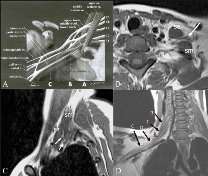
This composite educational graphic illustrates the normal anatomy of the brachial plexus through anatomical diagrams and Magnetic Resonance Imaging (MRI). Panel A is an anatomical diagram depicting the plexus architecture from roots (C5-T1) to terminal branches, labeled with musculoskeletal landmarks like the scalene muscles and coracoid process. Panel B (axial) and Panel C (sagittal) are T1-weighted MRI scans demonstrating the interscalene triangle, defined by the anterior scalene (sa) and middle scalene (sm) muscles. These muscles serve as primary radiological landmarks for identifying the neural roots and trunks (indicated by arrows). Panel D provides an oblique coronal T1-weighted MRI view, tracing the sequential segments of the right brachial plexus: roots (R), trunks (T), divisions (D), and cords (C). This resource is designed for medical education in radiology and neurology to assist in the localization of neural structures and the diagnostic evaluation of conditions like brachial plexopathy, neurogenic tumors, or Pancoast tumors.
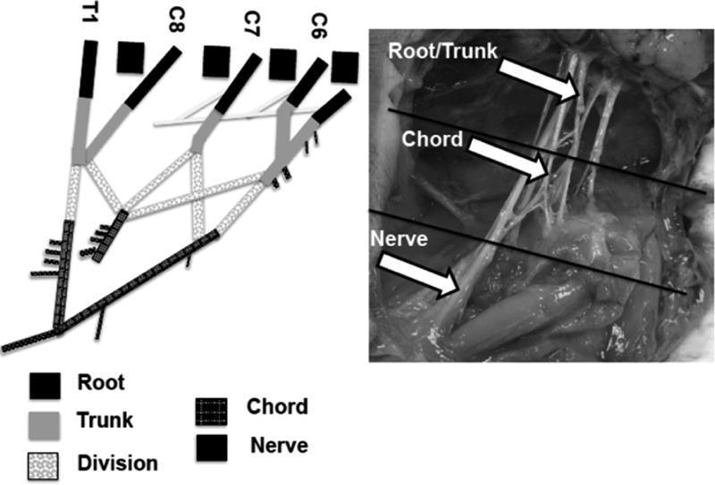
This composite educational material consists of a schematic diagram and a corresponding intraoperative clinical photograph illustrating the anatomical segments of the brachial plexus. The schematic on the left delineates the progression from spinal nerve roots (C6, C7, C8, and T1) through trunks, divisions, and chords to terminal nerves, using distinct grayscale patterns for each segment. It highlights the convergence of roots into upper, middle, and lower trunks and the subsequent formation of the medial and lateral cords through ventral divisions. The intraoperative photograph on the right provides clinical correlation in a neonatal model, with white arrows and horizontal lines demarcating the supraclavicular root/trunk region, the infraclavicular chord region, and the distal nerve branches. This comparison is used to facilitate identification of nerve bifurcations—such as the 'M' shape of the terminal branches—and to define anatomical boundaries for biomechanical or surgical study. The content is designed for intermediate to advanced medical education in peripheral nerve anatomy and neurosurgery.
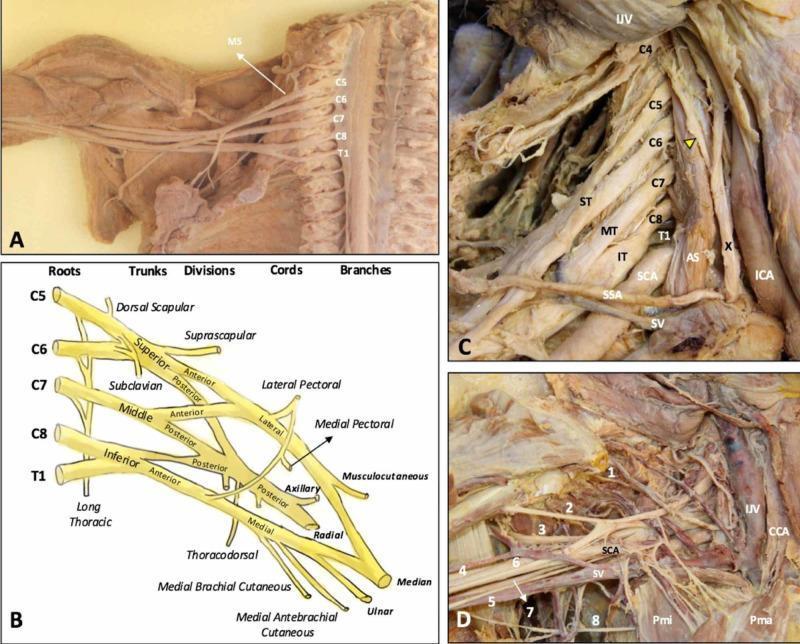
This composite educational graphic details the anatomy of the human brachial plexus (BP) through cadaveric dissections and a schematic diagram. (A) Cadaveric dissection of the cervical spine and axilla with the anterior scalene muscle removed, exposing the C5-T1 nerve roots emerging laterally to the middle scalene muscle (MS). (B) A structured schematic diagram illustrating the hierarchical organization of the BP from roots (C5-T1), trunks (Superior, Middle, Inferior), divisions (Anterior, Posterior), and cords (Lateral, Posterior, Medial) to terminal branches. (C) Dissection showing the roots in situ within the scalene triangle, formed between the anterior (AS) and middle scalene muscles, alongside major vessels including the subclavian artery (SCA) and internal jugular vein (IJV). The phrenic nerve (yellow arrowhead) is seen traversing the anterior scalene. (D) Detailed view of the infraclavicular and axillary regions showing terminal branches (1-8: suprascapular, musculocutaneous, axillary, radial, medial brachial cutaneous, median, ulnar, and intercostobrachial nerves) in relationship to the pectoralis minor (Pmi), pectoralis major (Pma), and subclavian vessels. This content provides essential topographical and clinical anatomy for understanding thoracic outlet syndrome and regional anesthesia.
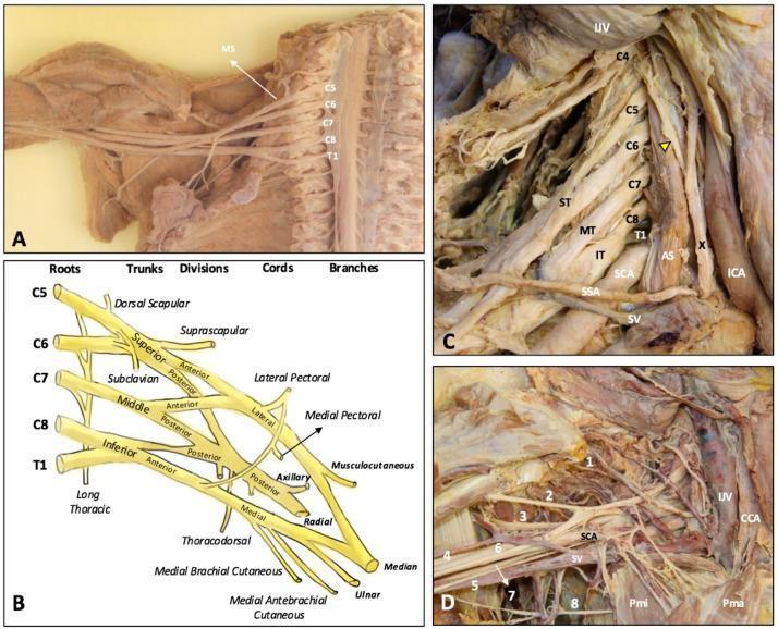
Educational anatomical resource illustrating the brachial plexus through cadaveric dissections (Panels A, C, D) and a schematic diagram (Panel B). Panel A shows the overview of the plexus and middle scalene muscle (MS) relative to the spinal cord. Panel B provides a detailed schematic of the classical brachial plexus organization: roots (C5-T1), superior (ST), middle (MT), and inferior (IT) trunks, anterior and posterior divisions, cords (lateral, medial, posterior), and terminal branches. Panel C displays a deep neck dissection highlighting the relationship between roots C4-T1 and the anterior scalene (AS), subclavian artery (SCA), internal jugular vein (IJV), and vagus nerve (X). A yellow arrowhead identifies the phrenic nerve. Panel D focuses on the infraclavicular and axillary regions, showing terminal branches: 1 (suprascapular), 2 (musculocutaneous), 3 (axillary), 4 (radial), 6 (median), and 7 (ulnar) nerves. Vascular landmarks include the common carotid artery (CCA) and subclavian vein (SV), alongside the pectoralis major (Pma) and minor (Pmi) muscles, providing clinical context for regional anesthesia and surgical approaches.
ANATOMY OF THE BRACHIAL PLEXUS: VARIOUS ROUTES OF BLOCKING AND COMPLICATIONS
1. INTRODUCTION
- The brachial plexus is the primary neural network supplying the entire upper extremity
- Brachial plexus block (BPB) provides surgical anaesthesia and/or analgesia for procedures on the shoulder, arm, elbow, forearm, wrist and hand
- It is one of the most commonly performed peripheral nerve blocks worldwide and forms the cornerstone of upper extremity regional anaesthesia
- Local anaesthetic may be deposited at any level along the plexus; choice of approach determines the level and distribution of the block
Exam Tip: The question asks for (a) Anatomy, (b) Various routes, and (c) Complications — answer all three parts for full marks.
2. ANATOMY OF THE BRACHIAL PLEXUS
2.1 Overview: "ROOTS, TRUNKS, DIVISIONS, CORDS, BRANCHES" — Mnemonic: "Robert Taylor Drinks Cold Beer"
| Level | Components | Vertebral Levels |
|---|---|---|
| Roots | Anterior primary rami | C5, C6, C7, C8, T1 |
| Trunks | Upper, Middle, Lower | Posterior triangle of neck |
| Divisions | Anterior + Posterior (×3 trunks = 6) | Behind clavicle |
| Cords | Lateral, Posterior, Medial | Axilla (around axillary artery) |
| Branches | 5 terminal nerves | Below pectoralis minor |
2.2 Roots
- Emerge from intervertebral foramina C5–T1
- Travel in grooves between anterior and posterior tubercles of transverse processes
- Pass between scalenus anterior and scalenus medius muscles
- C5 root — also receives contribution from C4 (prefixed plexus)
- T1 root — also receives contribution from T2 (postfixed plexus)
- Phrenic nerve (C3, C4, C5) — descends anterior to scalenus anterior; always at risk during proximal approaches
Viva Pearl: The phrenic nerve arises predominantly from C4 (with contributions from C3 and C5). It runs anterior to scalenus anterior and is blocked in virtually 100% of interscalene blocks, producing ipsilateral hemidiaphragmatic paresis.
2.3 Trunk Formation
| Trunk | Root Contribution | Location |
|---|---|---|
| Upper (Superior) | C5 + C6 | Posterior triangle |
| Middle | C7 alone | Posterior triangle |
| Lower (Inferior) | C8 + T1 | Posterior triangle |
- The trunks cross the base of the posterior triangle of the neck and the first rib
- Upper and middle trunks pass above the subclavian artery; lower trunk passes behind or below it
2.4 Divisions
- Each trunk divides into anterior and posterior divisions at the lateral border of the first rib/posterior to clavicle
- Total: 6 divisions (3 anterior + 3 posterior)
- Anterior divisions supply flexor compartments; posterior divisions supply extensor compartments
2.5 Cord Formation
| Cord | Division Contribution | Nerve Roots | Relation to Axillary Artery |
|---|---|---|---|
| Lateral | Anterior divisions of Upper + Middle trunks | C5, C6, C7 | Lateral/superior |
| Medial | Anterior division of Lower trunk | C8, T1 | Medial/inferior |
| Posterior | Posterior divisions of ALL three trunks | C5–T1 | Posterior |
- Cords are grouped around the 2nd part of the axillary artery (posterior to pectoralis minor)
- Surrounded by the axillary sheath (continuation of prevertebral fascia)
Exam Tip: Cord nomenclature is based on position relative to the 2nd part of the axillary artery, not the arm.
2.6 Terminal Branches (Mnemonic: "My Aunt Regularly Urges Me")
| Terminal Nerve | Cord of Origin | Roots | Motor | Sensory |
|---|---|---|---|---|
| Musculocutaneous | Lateral | C5–C7 | Coracobrachialis, biceps, brachialis | Lateral forearm (via lateral cutaneous nerve of forearm) |
| Axillary | Posterior | C5, C6 | Deltoid, teres minor | Regimental badge area |
| Radial | Posterior | C5–T1 | Extensors of arm/forearm/wrist/fingers | Posterior arm, forearm, dorsum of hand |
| Ulnar | Medial | C8, T1 | Intrinsic hand muscles (medial), flexor carpi ulnaris | Medial 1.5 fingers, medial palm |
| Median | Medial + Lateral (both cords) | C6–T1 | Thenar muscles, lateral lumbricals | Lateral 3.5 fingers, thenar eminence |
2.7 Branches Arising Proximal to Terminal Branches
| Branch | Origin | Roots |
|---|---|---|
| Dorsal scapular nerve | C5 root | C5 |
| Long thoracic nerve | C5, C6, C7 roots | C5–C7 |
| Nerve to subclavius | Upper trunk | C5, C6 |
| Suprascapular nerve | Upper trunk | C5, C6 |
| Lateral pectoral nerve | Lateral cord | C5–C7 |
| Medial pectoral nerve | Medial cord | C8, T1 |
| Medial cutaneous nerve of arm | Medial cord | C8, T1 |
| Medial cutaneous nerve of forearm | Medial cord | C8, T1 |
| Upper subscapular nerve | Posterior cord | C5, C6 |
| Thoracodorsal nerve | Posterior cord | C6–C8 |
| Lower subscapular nerve | Posterior cord | C5, C6 |
| Axillary nerve | Posterior cord | C5, C6 |
| Radial nerve | Posterior cord | C5–T1 |
2.8 Cutaneous Dermatomes of Upper Extremity
| Region | Nerve/Root |
|---|---|
| Shoulder cap | C4, C5 (axillary nerve) |
| Lateral arm | C5, C6 (axillary, lateral cutaneous) |
| Medial arm | C8, T1 (medial cutaneous nerve of arm) |
| Lateral forearm | C5, C6 (musculocutaneous → LACF) |
| Medial forearm | C8, T1 (medial cutaneous nerve of forearm) |
| Thumb/index/middle | C6 (median nerve) |
| Ring finger | C7 (shared median/ulnar) |
| Little finger/medial | C8 (ulnar nerve) |
| Axilla/inner arm | T2 (intercostobrachial — NOT blocked by BPB) |
Exam Tip: The intercostobrachial nerve (T2) is NOT part of the brachial plexus. It is NOT blocked by any brachial plexus approach. Tourniquet pain is mediated partly through T2.
2.9 Key Anatomical Diagram Description
- Vertebral column (C5–T1) on left
- Roots emerging between scalenus anterior and medius
- 3 trunks crossing posterior triangle with subclavian artery below
- Clavicle crossing
- 6 divisions behind clavicle
- 3 cords around axillary artery (label medial, lateral, posterior)
- 5 terminal branches emerging below pectoralis minor
- Label phrenic nerve on anterior scalenus anterior
- Label first rib as inferior boundary of supraclavicular fossa
- Label "interscalene" → "supraclavicular" → "infraclavicular" → "axillary" levels with arrows
3. VARIOUS ROUTES OF BLOCKING THE BRACHIAL PLEXUS
Classification of Approaches
BRACHIAL PLEXUS BLOCK APPROACHES
              |
    __________|__________
    |                   |
ABOVE CLAVICLE      BELOW CLAVICLE
(Supraclavicular)   (Infraclavicular)
    |                   |
1. Interscalene     3. Infraclavicular
2. Supraclavicular  4. Axillary
                    5. Costoclavicular (novel)
3.1 INTERSCALENE BRACHIAL PLEXUS BLOCK (ISB)
Level of Block
- Trunks (superior and middle) in the interscalene groove
Indications
- Shoulder surgery (arthroscopy, arthroplasty, rotator cuff repair)
- Proximal humerus fractures
- Clavicle surgery (partial)
- Acute shoulder pain / trauma
Patient Position
- Supine, head turned 30–45° to contralateral side, slight reverse Trendelenburg
Surface Anatomy / Landmarks
- Cricoid cartilage (C6 level) — identifies the level of the interscalene groove
- Posterior border of sternocleidomastoid (SCM)
- External jugular vein (often crosses at this level)
- Chassaignac's tubercle (anterior tubercle of C6 transverse process)
Ultrasound Technique
- Probe: High-frequency linear (10–15 MHz)
- Position: Transverse, lateral neck at C6 level
- Sonoanatomy:
- Identify carotid artery and internal jugular vein medially
- Identify scalenus anterior and scalenus medius muscles
- Brachial plexus roots/trunks appear as "traffic light" or "stoplight" sign — 3 hypoechoic round structures between the scalene muscles (C5 upper, C6 middle, C7 lower)
- Note: Vertebral artery lies medial and deep — must be avoided
- Needle: 22G, 50mm, short bevel or echogenic
- Approach: In-plane (lateral to medial) or out-of-plane
- Volume: 10–20 mL (5 mL may be sufficient for analgesia with reduced phrenic nerve block risk)
- Endpoint: Spread of LA seen around trunks; aspiration negative before each increment
Nerve Stimulator Endpoint
- Stimulation of upper trunk (C5, C6): deltoid contraction, shoulder abduction, or elbow flexion
- Acceptable at 0.2–0.5 mA
What is Blocked / What is Missed
| Blocked | Often Missed |
|---|---|
| C5, C6 (reliable) | C8, T1 (lower trunk — ulnar nerve) |
| Shoulder, upper arm | Medial forearm, hand (ulnar distribution) |
| Phrenic nerve (100%) | Intercostobrachial (T2) |
Key Complications
- Ipsilateral phrenic nerve block (100%) — hemidiaphragmatic paresis → absolute contraindication in contralateral phrenic nerve palsy or single lung
- Horner's syndrome — stellate ganglion block (25%)
- Pneumothorax (rare with US guidance)
- Vertebral artery injection → immediate CNS toxicity
- Intraspinal/epidural spread
- Subarachnoid injection → high/total spinal
Viva Pearl: ISB is the ONLY brachial plexus block where bilateral performance is absolutely contraindicated (bilateral phrenic nerve palsy → respiratory arrest).
3.2 SUPRACLAVICULAR BRACHIAL PLEXUS BLOCK
Level of Block
- Trunks and divisions at the first rib, as they cluster together before dividing
- Called the "spinal anaesthesia of the arm" — most complete and consistent block for the upper limb
Indications
- All surgeries below the mid-humerus (elbow, forearm, wrist, hand)
- Not ideal for shoulder surgery (C5, C6 proximal branches may be missed)
Patient Position
- Supine, head turned to contralateral side; arm adducted
Surface Anatomy / Landmarks
- Posterior border of SCM at clavicle
- Clavicle
- Subclavian artery pulsation in supraclavicular fossa
Ultrasound Technique
- Probe: High-frequency linear (12–15 MHz)
- Position: Parallel to and just above clavicle, coronal oblique
- Sonoanatomy:
- Subclavian artery — pulsatile, circular, anechoic
- First rib — hyperechoic line with acoustic shadow below the artery
- Pleura — bright hyperechoic line, deeper to first rib, with lung sliding
- Brachial plexus = "cluster of grapes" — multiple hypoechoic nodules lateral and superficial to the subclavian artery
- Needle: 22G, 50mm echogenic
- Approach: In-plane, lateral to medial
- Volume: 20–30 mL
- Corner pocket technique: LA deposited in the "corner pocket" between subclavian artery and first rib — achieves superior spread to lower trunk (prevents ulnar sparing)
Key Complications
- Pneumothorax — most significant risk (0.1–0.4% with US guidance)
- Phrenic nerve block (50–60%)
- Horner's syndrome
- Subclavian artery puncture/haematoma
Exam Tip: The pneumothorax risk is lower with US guidance but never zero — rib and pleura must be identified before needle insertion.
3.3 INFRACLAVICULAR BRACHIAL PLEXUS BLOCK
Level of Block
- Cords around the 2nd part of the axillary artery
Indications
- Procedures at or distal to the elbow
- Catheter placement (more comfortable than axillary)
- Obese patients, restricted neck movement
- When tourniquet is applied above elbow
Patient Position
- Supine, arm slightly abducted or at side
Surface Anatomy / Landmarks
- Coracoid process — medial border
- Infraclavicular fossa — below clavicle, medial to coracoid
Ultrasound Technique
- Probe: High-frequency linear or lower-frequency curvilinear (depending on depth)
- Position: Parasagittal below clavicle, medial to coracoid process
- Sonoanatomy:
- Axillary artery — round, pulsatile, anechoic, at 3–5 cm depth
- Axillary vein — compressible, medial
- Cords: Lateral cord = superficial/lateral (10 o'clock), Posterior cord = deep/posterior (6 o'clock), Medial cord = medial (8 o'clock) relative to artery
- Pectoralis major and minor muscles overlying
- Needle: 22G, 80–100mm echogenic
- Approach: In-plane (cephalad-to-caudad direction)
- Volume: 20–35 mL
- Endpoint: U-shaped (posterior) or circumferential spread around axillary artery
Key Complications
- Pneumothorax (less than supraclavicular)
- Axillary vessel puncture
- Infraclavicular haematoma
- No phrenic nerve risk
Viva Pearl: Infraclavicular block has lower phrenic nerve block rate and is preferred in patients with moderate pulmonary compromise. Catheter placement is more stable here than at axillary level.
3.4 AXILLARY BRACHIAL PLEXUS BLOCK
Level of Block
- Terminal nerves (median, ulnar, radial, musculocutaneous) in the axilla
Indications
- Forearm, wrist and hand surgery
- Day-case surgery
- Paediatric upper limb surgery
- High-risk pulmonary patients (no phrenic nerve risk)
Patient Position
- Supine, arm abducted 90° and externally rotated, elbow flexed
Surface Anatomy / Landmarks
- Axillary artery pulse (palpated in axilla)
- Anterior edge of axillary hair line
Ultrasound Technique
- Probe: High-frequency linear (12–15 MHz)
- Position: Transverse, in the axilla, high as possible
- Sonoanatomy:
- Axillary artery — central reference landmark
- Median nerve — superficial, lateral to artery (hyperechoic honeycomb, 11–1 o'clock)
- Ulnar nerve — medial, superficial to artery (9–11 o'clock)
- Radial nerve — deep/posterior to artery (5–7 o'clock)
- Musculocutaneous nerve — NOT periarterial; lies within coracobrachialis muscle or between coracobrachialis and biceps (must be blocked separately)
- Axillary vein — medial, compressible
- Needle: 22G, 50mm
- Approach: In-plane, lateral
- Volume: 5 mL per nerve (total 15–20 mL) — selective 4-injection technique
What is Missed
- Musculocutaneous nerve — exits plexus proximal to axilla; must be separately blocked in coracobrachialis
- Intercostobrachial nerve (T2) — requires subcutaneous infiltration along axilla
- Medial cutaneous nerve of arm — subcutaneous ring at axillary crease
Key Complications
- Axillary artery/vein puncture (most common)
- Haematoma
- No phrenic nerve risk
- No pneumothorax risk
Exam Tip: The axillary block is the safest BPB approach but least complete (musculocutaneous and intercostobrachial nerves missed). Requires 4-injection technique with US for best results.
3.5 COSTOCLAVICULAR BRACHIAL PLEXUS BLOCK (Novel/Recent)
Level of Block
- Cords in the costoclavicular space (between clavicle and first rib)
Sonoanatomy
- Probe: Linear, high-frequency, parallel to clavicle
- Cords appear as compact cluster lateral to subclavian artery in costoclavicular space
- Axillary artery and subclavian vein are medial
Advantages
- Cords more compact here than at infraclavicular level → single injection technique
- Excellent for catheter insertion
- Lower phrenic nerve block rate than supraclavicular/interscalene
- Suitable when arm cannot be moved (trauma, fracture)
Volume: 20–30 mL
Viva Pearl (2024–2026): Meta-analysis by Amaral et al. (2024) comparing costoclavicular vs. infraclavicular approaches found comparable efficacy with potentially lower complication rates for costoclavicular. Koo et al. (2023) confirmed significantly lower hemidiaphragmatic paralysis rate with costoclavicular versus interscalene block.
Comparison Table of All Approaches
| Feature | Interscalene | Supraclavicular | Infraclavicular | Axillary | Costoclavicular |
|---|---|---|---|---|---|
| Level blocked | Roots/Trunks | Trunks/Divisions | Cords | Terminal nerves | Cords |
| Best for | Shoulder | Arm/forearm/hand | Elbow to hand | Hand/wrist | Mid-arm to hand |
| Volume | 10–20 mL | 20–30 mL | 20–35 mL | 15–20 mL | 20–30 mL |
| C8/T1 coverage | Often incomplete | Good | Good | Good | Good |
| Phrenic nerve block | ~100% | 50–60% | Rare | None | Rare |
| Pneumothorax risk | Low | Highest | Low | None | Very low |
| Vascular injury | Vertebral artery | Subclavian artery | Axillary artery | Axillary artery/vein | Subclavian vessels |
| Horner syndrome | ~25% | Occasional | Rare | None | Rare |
| Catheter suitability | Good | Difficult | Excellent | Poor (arm position) | Excellent |
| Shoulder surgery | Best | Poor | Poor | Poor | Poor |
| Hand surgery | Poor | Good | Good | Best | Good |
| Pulmonary compromise | Avoid | Caution | Safe | Safest | Safe |
| Bilateral block | Contraindicated | Caution | Safe | Safe | Safe |
4. LOCAL ANAESTHETIC DRUGS
| Drug | Concentration | Volume | Onset | Duration (sensory) | Duration (motor) | Max safe dose |
|---|---|---|---|---|---|---|
| Lidocaine | 1.5–2% | 20–40 mL | 10–15 min | 2–4 h | 1–2 h | 4.5 mg/kg (7 mg/kg with epi) |
| Bupivacaine | 0.25–0.5% | 20–30 mL | 20–30 min | 8–16 h | 4–8 h | 2.5 mg/kg (max 175 mg) |
| Ropivacaine | 0.5–0.75% | 20–30 mL | 15–20 min | 8–14 h | 4–6 h | 3 mg/kg (max 200 mg) |
| Levobupivacaine | 0.375–0.5% | 20–30 mL | 15–25 min | 8–14 h | 4–6 h | 2.5 mg/kg (max 150 mg) |
- Dexamethasone 4–8 mg (IV or perineural) — extends block duration by 6–8 hours
- Dexmedetomidine 0.5–1 mcg/kg — extends sensory block by 2–4 hours
- Clonidine 75–150 mcg — modest prolongation
- Buprenorphine 0.3 mg — prolongs analgesia
5. PATIENT PREPARATION
- Consent: Informed written consent; explain procedure, risks, alternatives
- Monitoring: ECG, SpO2, NIBP, IV access mandatory
- Sedation: Midazolam 1–2 mg IV + fentanyl 25–50 mcg IV titrated (conscious sedation)
- Positioning: As per approach (detailed per block above)
- Asepsis: Sterile field, ultrasound probe sterile cover, skin antisepsis (chlorhexidine)
- Resuscitation: Lipid emulsion 20% intralipid must be available at point of care
- WHO block checklist: Patient identity, site marking, timeout, anticoagulation status
6. ASSESSMENT OF BLOCK
| Test | Nerve | Method |
|---|---|---|
| Shoulder abduction | C5, C6 (axillary + musculocutaneous) | Ask patient to abduct arm |
| Elbow flexion | C5, C6 (musculocutaneous) | Biceps strength |
| Wrist extension | C7 (radial) | Resist wrist drop |
| Thumb opposition | C8, T1 (median) | Pinch grip |
| Finger abduction | C8, T1 (ulnar) | Finger spreading |
| Pin-prick | All distributions | 2-point discrimination, ice |
| Onset | 15–30 minutes for full block | |
| Failed block | No sensory change at 30 min = failed |
7. COMPLICATIONS
Classification
COMPLICATIONS OF BRACHIAL PLEXUS BLOCK
            |
     _______|_______
     |             |
  SYSTEMIC      LOCAL
     |             |
   LAST        Nerve injury
   Seizure      Haematoma
   Cardiac      Pneumothorax
   arrest       Infection
              Phrenic palsy
              Horner syndrome
              Vascular injury
Systematic Complications Table
| Complication | Approach Most At Risk | Incidence | Prevention | Management |
|---|---|---|---|---|
| LAST | All | 0.1–0.3% | Aspiration, incremental injection, US guidance | ASRA LAST algorithm |
| Phrenic nerve block | Interscalene (100%), Supraclavicular (50–60%) | Very high | Low volume, distal approach | Avoid in contralateral palsy; O2, ventilatory support |
| Pneumothorax | Supraclavicular, Infraclavicular | 0.1–0.4% (US) | Identify first rib and pleura under US | O2; aspiration; chest drain if large |
| Horner syndrome | Interscalene, Supraclavicular | 25–75% | Cannot prevent with ISB | Reassurance; transient |
| Vascular puncture | All | 2–4% | Doppler, negative aspiration | Direct pressure; haematoma monitoring |
| Nerve injury | All | 0.04–0.2% | Avoid intraneural injection; limit pressure < 15 psi; US guidance | Neurological follow-up; most resolve in 4–6 weeks |
| Infection | All | Rare | Strict asepsis | Antibiotics; catheter removal |
| Block failure | Axillary (most, ~5–10%) | Variable | US guidance, adequate volume | Rescue block / GA supplement |
| Intraspinal injection | Interscalene | Rare but catastrophic | Do not direct needle medially | Immediate ACLS |
| Vertebral artery injection | Interscalene | Very rare | Colour Doppler; medial structures | Immediate LAST protocol |
8. MANAGEMENT OF LAST (LOCAL ANAESTHETIC SYSTEMIC TOXICITY)
RECOGNITION
Neurological: perioral tingling, tinnitus, metallic taste, confusion, seizures
Cardiac: arrhythmia, bradycardia, VT/VF, cardiovascular collapse
                    ↓
STOP INJECTION immediately
Call for help
                    ↓
AIRWAY MANAGEMENT
100% O2 via mask → intubate if seizures or unconscious
Prevent hypoxia (worsens LAST)
                    ↓
SEIZURE MANAGEMENT
Benzodiazepine FIRST: Midazolam 1–2 mg IV
or Propofol 0.5–1 mg/kg (if not cardiovascularly compromised)
Avoid large doses propofol (worsens cardiac depression)
                    ↓
CARDIOVASCULAR COLLAPSE
Epinephrine: small doses (10–100 mcg boluses)
Avoid vasopressin, calcium channel blockers, beta-blockers
                    ↓
LIPID EMULSION (20% Intralipid) — ASRA 2020
Bolus: 1.5 mL/kg IV over 1 minute
Infusion: 0.25 mL/kg/min
Repeat bolus ×2 if no improvement (at 3–5 min)
Double infusion rate to 0.5 mL/kg/min if persistent
Maximum dose: 12 mL/kg
                    ↓
CPR if cardiac arrest
Prolonged CPR (>60 minutes) with lipid emulsion
Consider cardiopulmonary bypass if available
                    ↓
POST-EVENT MONITORING
ICU/HDU for minimum 4–6 hours after bupivacaine toxicity
12 hours after cardiac arrest
| Drug | Dose |
|---|---|
| 20% Intralipid bolus | 1.5 mL/kg IV (100 mL for 70 kg adult) |
| 20% Intralipid infusion | 0.25 mL/kg/min (continuing) |
| Midazolam | 1–2 mg IV (seizures) |
| Epinephrine | 10–100 mcg IV boluses (cardiac arrest) |
| Propofol | 0.5–1 mg/kg (if no cardiac compromise) |
| Atropine | 0.5–1 mg IV (bradycardia) |
9. ANTICOAGULATION AND BRACHIAL PLEXUS BLOCK
| Drug | Last dose to block | Block to restart |
|---|---|---|
| Warfarin | INR ≤1.5 | 6 hours after (no catheter) |
| UFH prophylaxis | 4 hours | 1 hour |
| LMWH prophylaxis | 12 hours | 12 hours |
| LMWH therapeutic | 24 hours | 24 hours |
| Dabigatran | 72 hours (normal renal) | 6 hours |
| Rivaroxaban/Apixaban | 48 hours | 6 hours |
| Aspirin alone | No restriction | — |
| Clopidogrel | 5 days | — |
Important: For peripheral nerve blocks without deep planes (e.g., axillary, femoral), ASRA considers the risk of haematoma lower than neuraxial. Non-compressible sites (infraclavicular, paravertebral) require similar caution to neuraxial.
10. RECENT ADVANCES (2024–2026)
| Advance | Details |
|---|---|
| AI-assisted ultrasound | Automated nerve identification; real-time image enhancement (GE, Philips AI tools) |
| Needle tracking systems | Electromagnetic (Infiniti Medical) and optical tracking for real-time needle tip visualisation |
| Injection pressure monitoring | B-SMART, CompuFlo devices — maintain opening injection pressure < 15 psi to prevent intraneural injection |
| Liposomal bupivacaine (Exparel) | Extended-release formulation; 72-hour analgesia; FDA approved perineural; evidence in shoulder arthroplasty ISB (2024) |
| Continuous peripheral nerve catheters (CPNC) | Infraclavicular and costoclavicular preferred for catheter stability; elastomeric pumps for home use |
| Phrenic-sparing alternatives | Sub-pectoral ISB, anterior suprascapular nerve block, costoclavicular block — reduce phrenic paresis in high-risk pulmonary patients |
| Costoclavicular block | Established as viable infraclavicular alternative with compact cord clustering; meta-analysis 2024 confirms equivalence |
| 3D ultrasound / fusion imaging | Research phase; shows promise for complex anatomy |
| Point-of-care handheld ultrasound (Butterfly iQ+, Lumify) | Increasing use in trauma bays and resource-limited settings |
| ESAIC 2024 consensus | Emphasises ultrasound as standard of care; recommends injection pressure monitoring routinely |
11. CURRENT GUIDELINES SUMMARY
| Organisation | Key Recommendation |
|---|---|
| ASRA 2022 | US guidance standard of care; lipid emulsion must be available at block site; injection pressure monitoring recommended |
| ESRA 2023 | Recommends ultrasound + nerve stimulator combination for deep blocks; minimum effective volumes; anticoagulation guidelines published |
| ASA | Regional anaesthesia preferred where appropriate; monitors standard (ECG, SpO2, NIBP) mandatory during blocks |
| ESAIC 2024 | Endorses real-time US; promotes fascial plane concepts; recommends ERAS integration |
12. CLINICAL PEARLS
- "Stoplight" sign on US = 3 hypoechoic nodules between scalene muscles at interscalene level = C5 (superior), C6 (middle), C7 (lower)
- "Cluster of grapes" sign = brachial plexus at supraclavicular level
- At supraclavicular level, the entire plexus is most compact — hence "spinal of the arm"
- C8, T1 (lower trunk/medial cord) is MOST COMMONLY missed in interscalene and (sometimes) supraclavicular blocks — always supplement ulnar nerve for hand surgery
- Phrenic nerve is blocked in 100% of ISBs — always ask about contralateral phrenic palsy, COPD severity, and BMI
- The musculocutaneous nerve exits the plexus high in the axilla and must be separately blocked in the coracobrachialis muscle during axillary block
- Intercostobrachial nerve (T2) is never blocked by any BPB — supplement subcutaneous ring for tourniquet pain
- Never direct the needle medially during interscalene block — vertebral artery and intervertebral foramina lie medially; even 1 mL intrathecally causes total spinal
- Opening injection pressure > 15 psi suggests intraneural placement — stop injection immediately
- 20% Intralipid must be drawn up before every brachial plexus block — not just available in pharmacy
- For infraclavicular catheter placement, aim for the posterior cord position (6 o'clock behind artery) — single injection produces circumferential spread
- Ropivacaine 0.5% is the drug of choice for single-injection BPB balancing onset, duration and safety profile
- Dexamethasone 8 mg IV prolongs block duration comparably to perineural dexamethasone with a better safety profile
- Bilateral ISB is absolutely contraindicated — bilateral phrenic nerve palsy = respiratory arrest
- The costoclavicular approach is the fastest-emerging infraclavicular technique — cords are most compact here; single injection, no arm movement required
13. COMMON VIVA QUESTIONS
- Roots: C5–T1; Trunks: Upper (C5+C6), Middle (C7), Lower (C8+T1); Cords: Lateral (C5–C7), Posterior (C5–T1), Medial (C8, T1)
- Both phrenic nerves are blocked → bilateral hemidiaphragmatic paresis → respiratory failure requiring ventilation
- LA deposited in the groove between the subclavian artery and the first rib → ensures spread to lower trunk (C8, T1) preventing ulnar nerve sparing
- Sonographic appearance of brachial plexus at interscalene level: 3 round hypoechoic structures arranged vertically between anterior and middle scalene muscles
- It exits the brachial plexus proximal to the axilla, enters coracobrachialis muscle, and lies outside the axillary sheath at the level of block
- The initial pressure required to inject LA around the nerve. Pressure > 15 psi suggests intraneural needle tip position → risk of nerve damage → stop injection
- Local anaesthetic systemic toxicity from intravascular injection or systemic absorption. Treatment: stop injection, airway, oxygen, seizure management, 20% Intralipid bolus 1.5 mL/kg then infusion 0.25 mL/kg/min
- Ulnar nerve (C8, T1 from lower trunk) — lower trunk lies below and behind the subclavian artery, away from the primary injection site in the interscalene groove
- Ptosis, miosis, anhidrosis, enophthalmos from stellate ganglion block. Most common with interscalene block (25–75%). Transient, requires only reassurance.
- Same fascial compartment — it is the prevertebral fascia that surrounds the plexus from the interscalene groove proximally and continues as the axillary sheath distally. LA spreads proximally or distally within this sheath.
- Supraclavicular (0.1–0.4% with US guidance; historically up to 6% with landmark technique) due to proximity of pleural apex
- Separate injections for median nerve, ulnar nerve, radial nerve, and musculocutaneous nerve (in coracobrachialis) rather than single periarterial injection → higher success rate
- Infraclavicular catheter is more stable (less head movement), no phrenic nerve risk, better for hand/forearm surgery; interscalene catheter better for shoulder surgery but causes persistent phrenic palsy
- Anterior suprascapular nerve block; combined axillary nerve + suprascapular nerve block; sub-pectoral (subomohyoid) ISB with reduced volume (5 mL); costoclavicular block
- Patient refusal; infection at injection site; allergy to local anaesthetics; bilateral interscalene block; contralateral phrenic nerve palsy (for ISB/supraclavicular); coagulopathy (relative for most approaches)
14. HIGH-YIELD FACTS
| Parameter | Value |
|---|---|
| Roots | C5, C6, C7, C8, T1 |
| Upper trunk | C5 + C6 |
| Lower trunk | C8 + T1 |
| Phrenic nerve | C3, C4, C5 (anterior to scalenus anterior) |
| ISB phrenic block rate | ~100% |
| ISB volume | 10–20 mL (5 mL low-volume phrenic-sparing) |
| Supraclavicular volume | 20–30 mL |
| Infraclavicular volume | 20–35 mL |
| Axillary volume | 15–20 mL (5 mL/nerve) |
| Ropivacaine max dose | 3 mg/kg (200 mg) |
| Bupivacaine max dose | 2.5 mg/kg (175 mg) |
| Intralipid bolus | 1.5 mL/kg (20%) |
| Intralipid infusion | 0.25 mL/kg/min |
| Injection pressure limit | < 15 psi |
| Block onset | 15–30 minutes |
| Block failure definition | No sensory change at 30 minutes |
15. RAPID REVISION BOX
BRACHIAL PLEXUS — ONE PAGE REVISION
━━━━━━━━━━━━━━━━━━━━━━━━━━━━━━━━━━━━
ANATOMY MNEMONIC: Robert Taylor Drinks Cold Beer
Roots (C5–T1) → Trunks (3) → Divisions (6) → Cords (3) → Branches (5)

TRUNKS:  Upper=C5+C6 | Middle=C7 | Lower=C8+T1
CORDS:   Lateral=C5-C7 | Posterior=C5-T1 | Medial=C8,T1

TERMINAL NERVES (My Aunt Regularly Urges Me):
M-Musculocutaneous | A-Axillary | R-Radial | U-Ulnar | M-Median

APPROACH SELECTION:
Shoulder → INTERSCALENE (trunks) — phrenic risk!
Arm/Elbow → SUPRACLAVICULAR (divisions) — "spinal of arm"
Elbow/Hand → INFRACLAVICULAR or COSTOCLAVICULAR (cords)
Hand/Wrist → AXILLARY (terminal nerves) — safest

VOLUMES: ISB 10-20mL | Supraclav 20-30mL | Infraclav 20-35mL | Axillary 15-20mL

KEY COMPLICATIONS:
1. LAST → Intralipid 1.5 mL/kg bolus + 0.25 mL/kg/min
2. Phrenic palsy → O2, PPV if needed (ISB 100%, Supraclav 50-60%)
3. Pneumothorax → Supraclavicular (highest risk)
4. Horner → ISB/Supraclav (25-75%, transient)
5. Vertebral artery → ISB (never direct needle medially)
6. Intraspinal → ISB (catastrophic)

MISSED NERVES:
ISB → C8/T1 ulnar territory
Axillary → Musculocutaneous (block separately in coracobrachialis)
All BPBs → Intercostobrachial T2 (subcutaneous ring block)

BILATERAL ISB = ABSOLUTELY CONTRAINDICATED

INJECTION PRESSURE > 15 psi = STOP (intraneural)

LAST TREATMENT: Stop → Airway → O2 → Seizure Rx →
INTRALIPID 20% → 1.5 mL/kg bolus → 0.25 mL/kg/min infusion → CPR

ULTRASOUND SIGNS:
ISB: "Stoplight" (3 nodes between scalenes)
Supraclav: "Cluster of grapes" lateral to subclavian artery
Infraclav: Cords at 3, 6, 9 o'clock around axillary artery
Axillary: Median (11), Ulnar (9-11), Radial (5-7) around artery

RECENT ADVANCES (2024-2026):
Costoclavicular block | Liposomal bupivacaine | AI-US | Pressure monitoring
Phrenic-sparing ISB | Continuous catheters | Handheld US (Butterfly iQ+)
━━━━━━━━━━━━━━━━━━━━━━━━━━━━━━━━━━━━
- Miller's Anesthesia 10e, Chapter 42 (Upper Extremity Blocks)
- Barash Clinical Anesthesia 9e, Chapter 36 (Brachial Plexus)
- Morgan & Mikhail Clinical Anesthesiology 7e, Chapter on Regional Anaesthesia
- Amaral et al. "Infraclavicular versus costoclavicular approaches...systematic review and meta-analysis." Braz J Anesthesiol 2024 [PMID: 37748644]
- Oliver-Fornies et al. "Hemidiaphragmatic paralysis after ultrasound-guided brachial plexus blocks." J Clin Anesth 2025 [PMID: 40494113]
- Koo et al. "Hemidiaphragmatic paralysis after costoclavicular approach vs other brachial plexus blocks." Korean J Anesthesiol 2023 [PMID: 37127532]
- ASRA LAST Guidelines 2020 | ASRA Anticoagulation Guidelines 2022 | ESRA 2023 Consensus---
- Full anatomy with mnemonic, roots → trunks → divisions → cords → terminal branches with tables
- All 5 approaches (Interscalene, Supraclavicular, Infraclavicular, Axillary, Costoclavicular) with US technique, volumes, indications
- Comprehensive comparison table
- Complete complications with mechanism, prevention, management
- Full ASRA LAST algorithm with drug doses
- Anticoagulation guidelines (ASRA 2022 / ESRA 2023)
- Recent advances up to 2026 with supporting evidence
- 15 viva questions with model answers
- One-page rapid revision box
Let’s go random, but keep a count of which question we’ve discussed and which ones we left so that we can later discuss those questions, I’m telling the topic now let’s do erector spinal block, serratus anterior block and paravertebral blocks
📋 QUESTION TRACKER
✅ DISCUSSED
| # | Topic | Paper | Marks |
|---|---|---|---|
| 1 | Anatomy of Brachial Plexus + All Routes + Complications | P1/Q5, P2/Q5 (various) | 40–50 |
🔄 IN PROGRESS NOW
| # | Topic |
|---|---|
| 2 | Erector Spinae Plane (ESP) Block |
| 3 | Serratus Anterior Plane (SAP) Block |
| 4 | Paravertebral Block + Space |
⏳ REMAINING (from your list)
"erector spinae plane block" AND analgesia
"paravertebral block" AND thoracic analgesia
erector spinae plane block ultrasound sonoanatomy transverse process
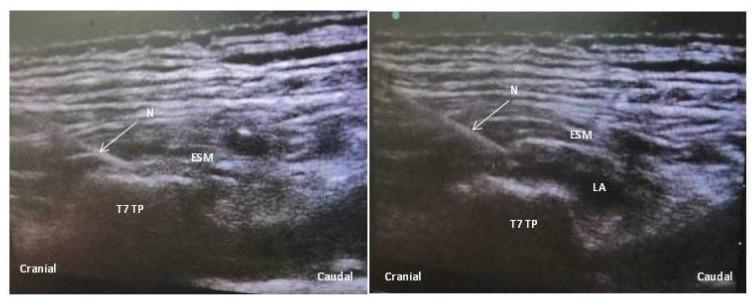
This diagnostic ultrasound image demonstrates the sonoanatomy of an Erector Spinae Plane (ESP) block at the level of the T7 thoracic vertebra. The image is presented in a sagittal view with cranial and caudal orientation markers. Key anatomical structures identified include the T7 transverse process (T7 TP), which appears as a hyperechoic, bony landmark with posterior acoustic shadowing, and the superficial erector spinae muscle (ESM), characterized by its striated echo texture. A hyperechoic needle (N) is visualized being advanced in a cranio-caudal direction through the ESM. In the post-injection frame, local anesthetic (LA) is seen as a hypoechoic (dark) fluid collection accumulating in the fascial plane deep to the ESM and superficial to the transverse process. The image illustrates the objective of the ESP block: the hydrodissection of the plane between the musculature and the bony processes to facilitate the cranial and caudal spread of anesthesia along the thoracic paravertebral space. This material is suitable for training in regional anesthesia, pain management, and ultrasound-guided procedural techniques.
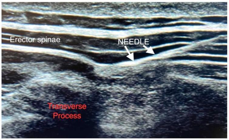
This diagnostic ultrasound image demonstrates the sonoanatomy required for an Erector Spinae Plane (ESP) block. The image shows a longitudinal view of the thoracic or lumbar paraspinal region. Key anatomical structures include the erector spinae muscle group, visible as superficial, parallel, hypoechoic layers, and the underlying transverse process of the vertebra, characterized by a highly echogenic (hyperechoic) curvilinear bony surface with posterior acoustic shadowing. An anesthetic needle is visualized using an in-plane technique, appearing as a linear hyperechoic structure. The needle tip is correctly positioned at the fascial plane between the deep aspect of the erector spinae muscle and the apex of the transverse process. This view is typical for regional anesthesia, illustrating the target site for local anesthetic deposition to achieve multisegmental analgesia. The image serves as an educational guide for ultrasound-guided interventional pain management and regional anesthesia protocols.
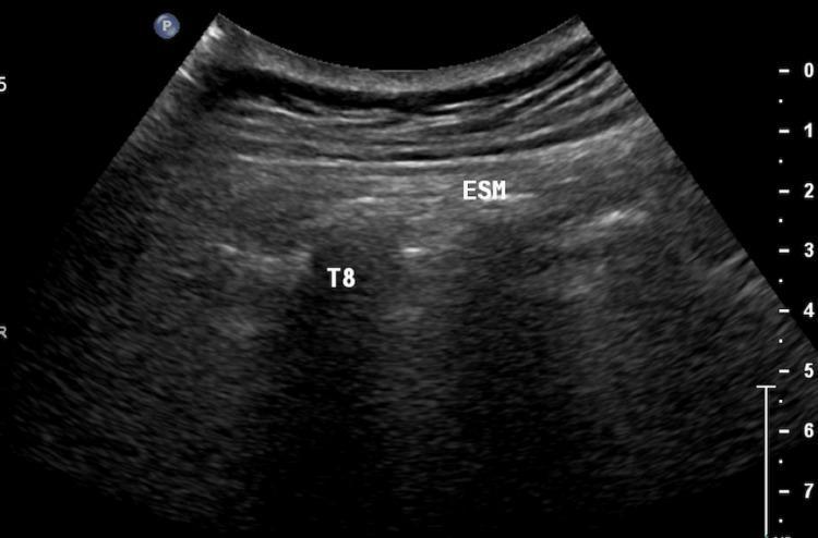
This diagnostic ultrasound image demonstrates the sonoanatomy of the thoracic paravertebral region in a sagittal plane, specifically used for the Erector Spinae Plane Block (ESPB). The image shows the erector spinae muscle (ESM) appearing as a thick, relatively hypoechoic tissue layer situated superficial to the bony structures. Deep to the ESM, the transverse process of the eighth thoracic vertebra (T8) is identified as a distinct, hyperechoic (bright) linear interface with characteristic posterior acoustic shadowing, typical of mineralized bone. The fascial plane between the deep surface of the ESM and the superficial aspect of the T8 transverse process is the target injection site for regional anesthesia. This visualization is essential for pain management procedures in anesthesiology and palliative care, allowing for real-time needle guidance and ensuring local anesthetic deposition deep to the erector spinae fascia to achieve multisegmental sensory blockade.
paravertebral space anatomy thoracic paravertebral block ultrasound

This composite image illustrates the clinical application and diagnostic visualization of an ultrasound-guided thoracic paravertebral block (PVB). Figure (a) is a clinical photograph showing the procedural setup, where a linear ultrasound probe is positioned on a patient's back between the fourth and fifth ribs. Figure (b) provides the corresponding ultrasound imaging of the thoracic anatomy. Key landmarks identified include the erector spinae muscle (visualized as a hypoechoic region superiorly), the hyperechoic curved surface of the transverse process, and the internal intercostal membrane (i.i.m.). The pleura is visible as a deeper, hyperechoic linear structure. An echogenic needle is shown in an in-plane approach, penetrating the internal intercostal membrane toward the paravertebral space. This visualization is critical for regional anesthesia in thoracic or breast surgery to ensure accurate local anesthetic deposition while avoiding pleural puncture. The educational focus is on the ultrasonographic identification of thoracic musculature and skeletal landmarks necessary for safe needle guidance.
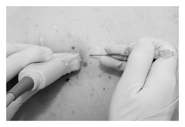
This procedural photograph demonstrates a thoracic paravertebral block technique under ultrasound guidance. A clinician, wearing white sterile medical gloves, uses a high-frequency linear ultrasound transducer covered with a protective sheath to visualize the underlying paraspinal anatomy. A generous amount of conductive ultrasound gel is applied to the skin of the thoracic region, which shows several benign-appearing nevi. A 16G Tuohy needle is being advanced using a craniocaudal in-plane technique, where the needle is oriented parallel to the long axis of the transducer beam to allow for continuous visualization of the needle shaft and tip. The needle features a clear plastic hub attached to extension tubing for local anesthetic delivery. This image illustrates the standard clinical setup for regional anesthesia, highlighting the spatial relationship between the transducer and the needle entry point to ensure precise localization within the paravertebral space.
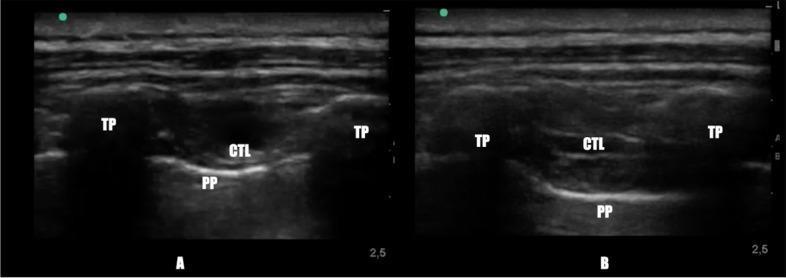
This diagnostic ultrasound comparison demonstrates the thoracic paravertebral space (TPVS) before and after the administration of a thoracic paravertebral block. Both images utilize a transverse scanning plane. Image A (pre-block) shows the baseline anatomy: the Transverse Process (TP) appears as a hypoechoic structure with acoustic shadowing; the Superior Costo-transverse Ligament (CTL) is a hyperechoic band; and the Parietal Pleura (PP) is identified as a deep, bright hyperechoic line. In Image A, the potential space between the CTL and PP is narrow. Image B (post-block) reveals the clinical significance of the procedure: the TPVS is significantly expanded by the injection of local anesthetic, visualized as a large wedge-shaped hypoechoic area. This expansion results in the downward displacement of the Parietal Pleura (PP) away from the Superior Costo-transverse Ligament (CTL). This comparison serves as an educational tool for identifying key sonoanatomy and confirming successful anesthetic spread during regional anesthesia in anesthesiology and pain management.
"serratus anterior plane" OR "serratus plane block"
serratus anterior plane block ultrasound latissimus dorsi ribs lateral chest
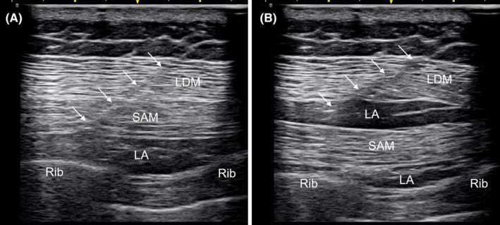
Diagnostic ultrasound images illustrating a serratus plane block (SPB) for regional anesthesia. The visuals demonstrate the layered musculoskeletal anatomy of the lateral chest wall. In both panels, the latissimus dorsi muscle (LDM) is the most superficial muscle layer, followed by the deeper serratus anterior muscle (SAM), which lies directly above the ribs. The ribs are identified by their characteristic curved hyperechoic margins with posterior acoustic shadowing. Image A shows a deep serratus plane block, where the local anesthetic (LA)—visible as an anechoic/hypoechoic fluid collection—is injected between the SAM and the underlying rib. Image B illustrates a dual-plane or superficial block, showing LA distribution both superficial to the SAM (between the LDM and SAM) and deep to the SAM. A Tuohy needle (indicated by white arrows) is visible using the in-plane technique, tracking through the muscle layers to the target fascia. This content is used to teach ultrasound-guided regional anesthesia techniques for pain management in thoracic and chest wall surgeries.
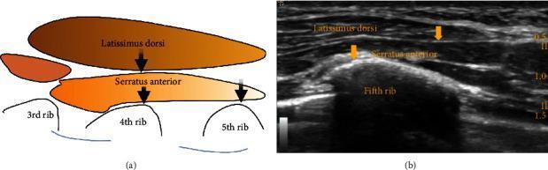
This educational graphic illustrates the ultrasound-guided serratus plane block technique through two side-by-side panels. Panel (a) is a simplified anatomical diagram showing the spatial relationship between thoracic muscles and ribs. The latissimus dorsi is depicted superficially over the serratus anterior muscle, which rests atop the 3rd, 4th, and 5th ribs. Panel (b) is a corresponding ultrasound image in the transverse plane at the axillary region. It identifies key landmarks including the latissimus dorsi, serratus anterior, and the hyperechoic surface of the fifth rib with an acoustic shadow below it. Yellow arrows in both panels indicate the primary targets for local anesthetic infiltration: the interfascial plane between the latissimus dorsi and serratus anterior, and the space deep to the serratus anterior muscle. The visual is designed to teach regional anesthesia residents and clinicians the correct needle placement for blocking the intercostobrachial and lateral intercostal nerves (T3-T9) for thoracic wall analgesia.
TRUNCAL REGIONAL NERVE BLOCKS
Enumerate Truncal Blocks — Discuss ESP Block, Serratus Anterior Plane Block, and Paravertebral Block
PART A: ENUMERATION OF TRUNCAL REGIONAL NERVE BLOCKS
Classification
TRUNCAL REGIONAL NERVE BLOCKS
            |
   _________|__________
   |                   |
NEURAXIAL            PERIPHERAL
(Epidural/Spinal)     Truncal Blocks
                       |
         ______________|_______________
         |              |              |
   PARAVERTEBRAL   INTERFASCIAL    INTERCOSTAL
   BLOCKS          PLANE BLOCKS    BLOCKS
         |              |
    Thoracic PVB   ESP Block
    Lumbar PVB     TAP Block
                   QL Block
                   PECS I / II
                   SAP Block
                   Serratus Ant. Block
                   Parasternal Block
Complete Enumeration Table
| Block | Target Plane | Coverage | Primary Use |
|---|---|---|---|
| Thoracic Paravertebral (TPVB) | Paravertebral space | Ipsilateral thorax/abdomen (unilateral epidural-like) | Thoracic surgery, mastectomy, rib fractures |
| Erector Spinae Plane (ESP) | Deep to erector spinae over TP | Multisegmental dorsal + ventral rami | Thoracic/abdominal surgery, rib fractures, spine surgery |
| Transversus Abdominis Plane (TAP) | Between IO and TA muscles | T6–L1 anterior abdominal wall (somatic only) | Abdominal surgery, ERAS |
| Quadratus Lumborum (QL) | Around QL muscle (Types I, II, III, IV) | T6–L1 (broader than TAP, some visceral) | Abdominal, hip, renal surgery |
| Serratus Anterior Plane (SAP) | Superficial or deep to serratus anterior | Lateral chest wall T2–T9 | Thoracotomy, breast surgery, rib fractures, VATS |
| PECS I | Between Pec major and minor | Medial and lateral pectoral nerves | Breast implant, subpectoral surgery |
| PECS II (Modified) | Between Pec minor and serratus anterior | ICBN, T3–T6 intercostals, long thoracic | Mastectomy, axillary dissection |
| Intercostal Nerve Block | Intercostal groove (inferior rib border) | T1–T12 individual intercostal nerves | Rib fractures, post-thoracotomy, drainage |
| Parasternal Block | Parasternally between ribs | Internal mammary perforators (T1–T6) | Cardiac surgery, sternotomy |
| Rhomboid Intercostal Block | Between rhomboid and intercostal muscles | T4–T9 | Thoracic pain |
| Lumbar Plexus (Psoas Compartment) | Within psoas muscle | L1–L4 | Hip/femur surgery |
Exam Tip: In the exam, enumerate ALL truncal blocks first in a table — this scores well even if you only discuss 2–3 in detail. Always state whether a block has somatic only or somatic + visceral + sympathetic coverage.
BLOCK 1: ERECTOR SPINAE PLANE (ESP) BLOCK
1. DEFINITION AND INTRODUCTION
- Definition: A fascial plane block in which local anaesthetic is deposited deep to the erector spinae muscle group and superficial to the transverse process of the vertebra
- First described by Forero et al., 2016 for neuropathic chest pain (thoracic T5 level)
- Mechanism: LA spreads within the ESP fascial plane → permeates anteriorly through the intertransverse connective tissue → enters the paravertebral space → blocks dorsal rami, ventral rami, and sympathetic nerve fibres
- The ESP plane runs from cervical spine to sacrum bilaterally
Viva Pearl: The exact mechanism of the ESP block remains incompletely understood. Proposed pathways include: (1) direct paravertebral spread via intertransverse ligament, (2) retrolaminar spread, (3) neural soaking of dorsal rami at transverse process level.
2. RELEVANT ANATOMY
Erector Spinae Muscle Group (Mnemonic: "I Love Spine")
| Muscle | Location | Function |
|---|---|---|
| Iliocostalis | Lateral column | Lateral extension |
| Longissimus | Intermediate | Extension and rotation |
| Spinalis | Medial column | Extension |
- The 3 muscles lie bilaterally alongside the vertebral column
- High thoracic (T1–T6): Lie deep to trapezius and rhomboid muscles
- Low thoracic (T7–T12): Lie deep to latissimus dorsi muscle
- Lumbar: Covered by thoracolumbar fascia
Key Relationships at the Transverse Process Level
SKIN
  ↓
Subcutaneous fat
  ↓
Trapezius / Rhomboid / Latissimus dorsi
  ↓
ERECTOR SPINAE MUSCLE GROUP
  ↓
[ESP FASCIAL PLANE] ← TARGET injection plane
  ↓
TRANSVERSE PROCESS (osseous backstop)
  ↓
Intertransverse ligament
  ↓
PARAVERTEBRAL SPACE (LA spreads here)
  ↓
Spinal nerve (dorsal + ventral rami + sympathetics)
Important Anatomical Points
- The transverse process acts as the osseous backstop — protects from inadvertent pleural puncture
- At thoracic levels: TP is at 2.5–3 cm depth
- Lateral border of TP is the danger zone for advancing too deep → paravertebral space, pleura
- The dorsal scapular artery and posterior intercostal arteries are nearby
Dermatomes Covered
| Level of Injection | Levels Covered |
|---|---|
| T5 | Typically T3–T9 (4–6 levels up/down) |
| T7 | T5–T11 |
| L3 | L1–L5 |
3. SURGICAL AND CLINICAL INDICATIONS
| Category | Indication |
|---|---|
| Thoracic surgery | VATS, thoracotomy, pneumonectomy |
| Breast surgery | Mastectomy, reconstruction, implant |
| Abdominal surgery | Laparoscopic/open cholecystectomy, hepatic, renal |
| Cardiac surgery | Cardiac surgery analgesia (bilateral ESP T4) |
| Spine surgery | Lumbar ESP block for posterior spine procedures |
| Trauma | Multiple rib fractures |
| Chronic pain | Post-mastectomy pain, post-thoracotomy pain syndrome |
| ICU | Non-invasive multimodal analgesia for rib fractures |
| ERAS | Component of opioid-sparing protocols |
| Paediatrics | Truncal/thoracic procedures in children |
4. SONOANATOMY AND ULTRASOUND-GUIDED TECHNIQUE
Probe
- Linear high-frequency probe (13–6 MHz) — routine adults
- Curvilinear (8–3 MHz) — obese patients or deep thoracic levels
Patient Position
- Sitting (preferred) — with head flexed forward, arms across chest
- Lateral decubitus or prone (alternative)
Scanning Protocol
| Step | Action |
|---|---|
| Step 1 | Place probe parasagittally 2–3 cm lateral to midline at target level |
| Step 2 | Identify bony structures: transverse process (TP) — rectangular, short, hyperechoic with acoustic shadow |
| Step 3 | Distinguish TP from rib — ribs are deeper, more curved; TP at thoracic level is a "shallow rectangular shelf" |
| Step 4 | Identify erector spinae muscle superficial to TP — heterogeneous, fusiform, striated |
| Step 5 | Identify fascial interface (thin bright line) between erector spinae and TP — this is the TARGET |
| Step 6 | Note pleura as bright hyperechoic sliding line at rib level — deeper and lateral to TP |
Sonographic Landmarks
PARASAGITTAL US VIEW (thoracic ESP):
─────────────────────────────────────
[Skin]
[Trapezius / Rhomboids / Lat dorsi]
[ERECTOR SPINAE MUSCLE] ← striated, hypoechoic
[ESP PLANE] ← bright fascial line = TARGET
[TRANSVERSE PROCESS] ← hyperechoic shelf + acoustic shadow
                        (NOT the rib — rib is lateral and deeper)
─────────────────────────────────────
Exam Tip — Common Mistake: Confusing the transverse process with the rib on US. TP = rectangular, more medial, with broad acoustic shadow. Rib = curved, lateral, deeper.
Needle Technique
- Needle: 22G 80–100 mm echogenic block needle
- Approach: In-plane (cranio-caudal OR caudo-cranial)
- Direction: Needle tip contacts periosteum of TP
- Hydrodissection: Inject 1–2 mL saline — erector spinae muscle lifts off TP = correct plane confirmed
- Injection: 20–30 mL LA (single injection); 30–50 mL for extended coverage
- Spread: Watch LA lift erector spinae off TP and track cranially + caudally along the plane
Drug Choice and Volumes
| Drug | Concentration | Volume | Duration |
|---|---|---|---|
| Ropivacaine | 0.375–0.5% | 20–30 mL | 12–18 h |
| Bupivacaine | 0.25–0.375% | 20–25 mL | 12–18 h |
| Levobupivacaine | 0.25–0.375% | 20–25 mL | 12–18 h |
| Dexamethasone | 4–8 mg | Add to injectate | Extends by 6–8 h |
- Bilateral ESP: Halve volumes per side (max 10–15 mL per side)
- Continuous catheter: Ropivacaine 0.2% at 5–10 mL/h
5. ASSESSMENT OF BLOCK
- Sensory: Pin-prick testing along dermatomes T3–T9 (depending on injection level)
- Motor: No motor block expected (fascial plane block — purely somatic +/- visceral)
- Onset: 15–30 minutes for full sensory blockade
- Duration: 12–24 hours with long-acting LA
6. ADVANTAGES AND DISADVANTAGES
| Advantages | Disadvantages |
|---|---|
| Simple, superficial plane | Mechanism incompletely understood |
| Osseous backstop (TP) — inherently safer | Variable and unpredictable spread |
| Low risk of vascular or pleural injury | Inferior analgesia vs. PVB (RCT evidence) |
| Easy catheter placement | Large volumes required |
| Suitable for novices / non-specialist settings | No reliable visceral analgesia |
| Bilateral performance possible | Bilateral LAST risk with high volumes |
| Covers dorsal rami (back pain component) | Evidence still evolving |
7. COMPLICATIONS
| Complication | Incidence | Prevention | Management |
|---|---|---|---|
| LAST | Rare but real (high vascularity) | Aspiration, incremental injection | ASRA LAST protocol + 20% Intralipid |
| Pneumothorax | Reported (rare) | TP as backstop; don't advance lateral to TP | O2, aspiration/drain if large |
| Epidural/intrathecal spread | Very rare (deep plane access) | Correct plane identification | Resuscitation, ITU |
| Block failure | 15–30% | US guidance, adequate volume | Rescue analgesia/rescue block |
| Haematoma | Rare | Aspiration; anticoagulation check | Conservative/surgical |
| Infection | Rare (catheter) | Strict asepsis | Antibiotics; catheter removal |
8. RECENT EVIDENCE (2024–2026)
- Yang et al. Network Meta-analysis, Pain Physician 2024 [PMID: 39621976]: For thoracic surgery analgesia — PVB ranked superior to ESP; ESP was superior to intercostal and systemic analgesia
- Gamberini et al. Bayesian Network Meta-analysis, Am J Emerg Med 2025 [PMID: 39740311]: In blunt thoracic trauma — PVB ranked highest; ESP block was effective and superior to systemic analgesia for rib fractures
- ESAIC 2024: Endorses ESP as first-line option where PVB expertise is unavailable; recommends pressure monitoring and US guidance as standard of care
BLOCK 2: SERRATUS ANTERIOR PLANE BLOCK (SAP BLOCK)
1. DEFINITION AND INTRODUCTION
- Definition: An ultrasound-guided interfascial plane block in which local anaesthetic is deposited superficial or deep to the serratus anterior muscle at the mid-axillary line to anaesthetise the lateral chest wall
- First described by Blanco et al., 2013
- Primarily blocks the lateral cutaneous branches of the intercostal nerves (T2–T9)
- Two variants: Superficial SAP (between latissimus dorsi and serratus anterior) and Deep SAP (between serratus anterior and ribs)
2. RELEVANT ANATOMY
Serratus Anterior Muscle
- Origin: Lateral surfaces of upper 8–9 ribs
- Insertion: Medial border of scapula (anterior/costal surface)
- Innervation: Long thoracic nerve (C5, C6, C7)
- Function: Protracts and rotates scapula; stabilises scapula during arm movements
- Relations:
- Superficial: Latissimus dorsi (posterolaterally), pectoralis major/minor (anteriorly)
- Deep (internal surface): Ribs and intercostal spaces, parietal pleura
- In the plane: Thoracodorsal artery (between latissimus dorsi and serratus anterior — Doppler essential)
- Intercostobrachial nerve (ICBN), T2–T9 lateral cutaneous branches run within/between these fascial planes
Nerves Blocked
| Nerve | Description |
|---|---|
| Lateral cutaneous branches of intercostals T2–T9 | Primary block target |
| Intercostobrachial nerve (ICBN, T2) | Axilla and upper medial arm |
| Long thoracic nerve (C5–C7) | Motor to serratus anterior |
| Thoracodorsal nerve (C6–C8) | Motor to latissimus dorsi |
Viva Pearl: SAP block does not cover the medial chest wall, anterior chest, or visceral pain. Medial branch (costomediastinal) is not covered. Hence not adequate as sole anaesthetic for thoracotomy.
Cutaneous Coverage
| Plane | Coverage |
|---|---|
| Superficial SAP | T2–T9 lateral cutaneous; ICBN; axilla; upper arm (medial) |
| Deep SAP | T2–T9 lateral cutaneous (equivalent sensory, easier access) |
3. CLINICAL INDICATIONS
| Category | Indication |
|---|---|
| Thoracic surgery | VATS, video-assisted thoracoscopy, thoracotomy (adjunct) |
| Breast surgery | Mastectomy, sentinel node biopsy, breast reconstruction |
| Trauma | Multiple rib fractures (lateral chest) |
| Chest wall | Post-thoracotomy pain syndrome |
| ICU | Rib fracture analgesia without neuraxial risk |
| ERAS | Opioid-sparing component |
| Drain insertion | Chest drain analgesia |
4. SONOANATOMY AND ULTRASOUND-GUIDED TECHNIQUE
Probe
- Linear high-frequency (13–6 MHz) — standard
- Transverse orientation at mid-axillary line
Patient Position
- Supine with arm abducted (ipsilateral arm above head) — preferred
- Lateral decubitus (alternative)
Scanning at Mid-Axillary Line, 4th–5th Rib Level
LATERAL CHEST WALL US (Transverse view at mid-axillary line):
─────────────────────────────────────────────────────────────
[Skin]
[Subcutaneous fat]
[LATISSIMUS DORSI MUSCLE] ← superficial layer
[SUPERFICIAL SAP PLANE] ← between LD and SAM = Target 1
[SERRATUS ANTERIOR MUSCLE] ← scalloped/fan-shaped
[DEEP SAP PLANE] ← between SAM and rib = Target 2
[RIB] ← hyperechoic curved surface + acoustic shadow
[PLEURA] ← bright hyperechoic line between rib shadows
─────────────────────────────────────────────────────────────
DOPPLER: Thoracodorsal artery in superficial plane — AVOID
Technique Steps
| Step | Action |
|---|---|
| 1 | Probe at 4th–5th intercostal space, mid-axillary line, transverse orientation |
| 2 | Identify latissimus dorsi, serratus anterior, ribs, pleura |
| 3 | Apply colour Doppler — identify thoracodorsal artery (between LD and SAM) |
| 4 | Insert 22G 50mm needle in-plane (posterior to anterior) |
| 5 | Deep SAP: Advance needle tip between SAM and rib surface — inject first |
| 6 | Superficial SAP: Withdraw needle to plane between LD and SAM — inject second |
| 7 | Aspirate before each injection; observe LA spread in plane |
Clinical Pearl: Always perform Deep SAP before Superficial SAP — once superficial plane is filled with LA, it becomes difficult to visualise deep structures.
Drug Doses
| Drug | Volume (single plane) | Volume (dual plane) |
|---|---|---|
| Ropivacaine 0.375% | 20–25 mL | 15 mL each plane |
| Bupivacaine 0.25% | 20–25 mL | 15 mL each plane |
| Paediatric (ropivacaine 0.2%) | 0.5 mL/kg per injection (max 3 mg/kg) |
5. ADVANTAGES AND DISADVANTAGES
| Advantages | Disadvantages |
|---|---|
| Simple, safe technique | Only lateral chest wall covered (not medial/anterior) |
| Superficial plane — low risk | No visceral analgesia |
| No pneumothorax risk (rib as backstop) | Not adequate as sole anaesthetic |
| No vascular injury risk (if Doppler used) | Thoracodorsal artery in plane |
| Easy catheter placement | Variable spread |
| No haemodynamic effects | Limited evidence vs. PVB |
6. COMPARISON: SAP vs. PVB (from Wang & Li, BMC Anesthesiol 2025 [PMID: 41087941])
- SAP block and PVB showed comparable postoperative pain scores (VAS/NRS) at 6h and 24h
- PVB had superior analgesia at 12h
- SAP had lower complication rates (no pneumothorax, no hypotension)
- Conclusion: SAP is a safer alternative where PVB expertise is unavailable
BLOCK 3: THORACIC PARAVERTEBRAL BLOCK (TPVB)
1. DEFINITION
- Definition: Injection of local anaesthetic into the thoracic paravertebral space (TPVS) — a wedge-shaped anatomical compartment lateral to the vertebral body — producing ipsilateral somatic and sympathetic nerve block over multiple contiguous thoracic dermatomes
- Often described as a unilateral, segmental epidural equivalent with superior haemodynamic profile
2. ANATOMY OF THE THORACIC PARAVERTEBRAL SPACE
Boundaries (Mnemonic: "SPAM" — Superior, Posterior, Anterior, Medial)
| Wall | Structure |
|---|---|
| Posterior | Superior costotransverse ligament (SCL) |
| Anterolateral | Parietal pleura (most important danger) |
| Medial | Vertebral body + intervertebral disc + intervertebral foramen |
| Superior/Inferior | Heads of the ribs (not a true closed space — communicates across levels) |
Contents of the TPVS
- Spinal nerve (at intervertebral foramen)
- Dorsal ramus (posterior primary rami)
- Ventral ramus (anterior primary rami) — main target
- Sympathetic chain (anteriorly, near vertebral body)
- Intercostal vessels
- Loose areolar fatty tissue
- Endothoracic fascia (separates pleural from extrapleural compartment)
Key Anatomical Points
- TPVS is a wedge-shaped space — apex medially at IVF, base laterally at pleura
- Communicates freely with adjacent levels — hence single injection can spread multiple levels
- At thoracic levels: TPVS depth from skin = 4–5 cm in average adults
- The superior costotransverse ligament (SCL) is the key posterior boundary — a firm fibrous band between the transverse process and the rib above
- Endothoracic fascia divides the PVS into anterior (pleural) and posterior (extrapleural) compartments
Exam Tip: The paravertebral space communicates medially with the epidural space (especially if large volumes used) — this explains ipsilateral and occasionally bilateral blocks with PVB.
Diagram Description — Draw in Exam
CROSS-SECTION OF THORACIC PARAVERTEBRAL SPACE:

        [Spinous process]
               |
        [Lamina + Ligamentum flavum]
               |
        [EPIDURAL SPACE]
               |         IVF
        [Vertebral body] — [SPINAL NERVE] ——→ PARAVERTEBRAL SPACE
               |                              |
               |                    [Superior Costotransverse Lig.]
               |                              | (posterior wall)
               |                    [Rib — head and neck]
               |                              |
               |                    [PARIETAL PLEURA]
               |                        (anterior wall)
               ↓
         Sympathetics (anterolateral)
3. SURGICAL AND CLINICAL INDICATIONS
| Category | Indication |
|---|---|
| Thoracic surgery | Thoracotomy, VATS, pneumonectomy, oesophagectomy |
| Breast surgery | Mastectomy ± axillary clearance (T2–T6) |
| Abdominal surgery | Open cholecystectomy, hepatic resection, nephrectomy, inguinal hernia |
| Cardiac | Off-pump CABG, minimal-access cardiac surgery |
| Trauma | Multiple rib fractures (most evidence-based indication for rib fractures) |
| Acute pain | Post-thoracotomy pain |
| Chronic pain | PTPS, post-mastectomy pain |
| ICU | Rib fracture multimodal analgesia |
| ERAS | Component of opioid-free ERAS protocols |
| Herpes zoster | Intercostal nerve involvement |
4. LANDMARK-BASED TECHNIQUE
Patient Position
- Sitting, spine flexed forward; or lateral decubitus
Surface Anatomy
- Identify spinous processes (count from C7 prominens downwards for thoracic)
- Mark a point 2.5 cm lateral to the midpoint of the superior edge of each spinous process
- Important: At thoracic levels, due to the steep caudal angulation of spinous processes, the T4 nerve root is accessed lateral to T3 spinous process
Needle Technique (Classic/Landmark)
STEP 1: Insert 20G Tuohy needle PERPENDICULAR to skin
STEP 2: Contact TRANSVERSE PROCESS at 2.5–4 cm depth
STEP 3: Walk needle CAUDALLY off the TP
STEP 4: Advance 1–1.5 cm BEYOND TP tip → "loss of resistance"
         through superior costotransverse ligament
STEP 5: Aspiration — negative blood and air
STEP 6: Inject LA — observe "clicks" as plunger advances (loss of resistance)
STEP 7: Volume 3–5 mL per level (landmark technique)
Viva Pearl: The loss of resistance in PVB occurs as the needle passes through the superior costotransverse ligament — this is the classical tactile endpoint (like epidural LOR technique). However, US guidance has made this more reliable.
5. ULTRASOUND-GUIDED TECHNIQUE
Probe
- Linear probe (13–6 MHz) — standard
- Curvilinear for deeper structures in obese patients
Probe Position and Views
- Probe perpendicular to spine at target level
- Identify: spinous process (medial), transverse process, costotransverse joint, rib (lateral), parietal pleura (anterior to rib)
- TPVS seen as wedge-shaped hypoechoic space between SCL and pleura
- Probe 2–3 cm lateral to midline
- See: erector spinae muscles, transverse processes, ribs, TPVS, and pleura
- LA injection: watch anterior displacement of pleura = correct TPVS injection confirmed
Needle Technique (US-Guided)
| Step | Action |
|---|---|
| 1 | Position probe parasagittally 2–3 cm lateral to midline |
| 2 | Identify TP, ribs, erector spinae, pleura |
| 3 | Insert 20G Tuohy needle in-plane, cranio-caudal direction |
| 4 | Needle tip through SCL → enters TPVS |
| 5 | Inject 1–2 mL saline — pleura displaced anteriorly (confirmation) |
| 6 | Inject LA in increments after negative aspiration |
| 7 | Watch LA spread and pleural displacement |
Drug Doses and Volumes
| Approach | Volume per Level | Total Levels | Drug |
|---|---|---|---|
| Single injection (continuous catheter) | 15–20 mL | 1 level | Ropivacaine 0.5% or Bupivacaine 0.5% |
| Multiple injection technique | 3–5 mL/level | 3–5 levels | Same |
| Catheter infusion | 5–10 mL/h | Continuous | Ropivacaine 0.2% |
- Mastectomy (T2–T6): 3 injections at T3, T4, T5 or single catheter at T4
- Rib fractures: Level of each fractured rib
6. COMPLICATIONS OF TPVB
| Complication | Incidence | Details |
|---|---|---|
| Pneumothorax | 0.5–1% (US) | Most serious; due to pleural puncture |
| Hypotension | 5–10% (multilevel) | Sympathectomy; bilateral PVB = bilateral sympathectomy |
| Epidural spread | 1–5% | Via intervertebral foramen; bilateral block, hypotension |
| Intravascular injection | 2–4% | Intercostal vessels; LAST |
| Subarachnoid injection | Rare | Catastrophic |
| Horner syndrome | ~5–10% (high thoracic) | Stellate ganglion involvement — transient |
| Haematoma | Rare | Anticoagulation precautions essential |
| Block failure | 10–15% | Variable spread |
| Infection | Rare | Strict asepsis |
Exam Tip: The most feared complication of TPVB is pneumothorax — always identify pleura on US BEFORE needle insertion. Anterior displacement of pleura during injection is the confirmation sign.
7. ANTICOAGULATION CONSIDERATIONS FOR TPVB
- TPVB is classified as a deep, non-compressible block by ASRA 2022
- Therefore, applies similar anticoagulation rules as neuraxial blocks
- LMWH therapeutic dose: Wait 24 hours before performing TPVB
- Warfarin: INR ≤ 1.5 before performing
- DOACs (rivaroxaban, apixaban): Wait 48 hours
8. COMPARISON OF ALL THREE BLOCKS
| Feature | TPVB | ESP Block | SAP Block |
|---|---|---|---|
| Level of block | Paravertebral space | Fascial plane over TP | Fascial plane around serratus anterior |
| Primary target | Spinal nerve (dorsal + ventral rami + sympathetics) | Dorsal + ventral rami via diffusion | Lateral cutaneous branches T2–T9 |
| Coverage | Ipsilateral thorax/abdomen, unilateral multi-segmental | Multisegmental thorax/abdomen (variable) | Lateral chest wall T2–T9 only |
| Visceral analgesia | Yes (sympathetics) | Variable / uncertain | No |
| Volume | 3–5 mL/level or 15–20 mL single | 20–30 mL | 20–25 mL/plane |
| Depth from skin | 4–5 cm | 2–3 cm | 1–3 cm |
| Proximity to pleura | Direct (high risk) | Indirect (TP backstop) | Rib backstop (lowest risk) |
| Pneumothorax risk | 0.5–1% | Rare | Very rare |
| Haemodynamic effect | Sympathectomy possible | Minimal | None |
| Ease of performance | Moderate–difficult | Easiest | Easy |
| Evidence quality | Strongest (oldest) | Growing (RCTs 2023–2026) | Moderate |
| Catheter suitability | Excellent | Good | Good (but risk of dislodgement) |
| Bilateral safety | Caution (bilateral sympathectomy) | Reduce volume | Safe |
| ERAS integration | Excellent | Excellent | Good |
| Best for | Thoracotomy, mastectomy, rib fractures | General truncal, spine surgery, when PVB not available | Lateral chest wall, VATS |
9. RECENT ADVANCES (2024–2026)
| Advance | Evidence |
|---|---|
| AI-assisted US identification of TPVS | Prototype systems — research phase |
| Injection pressure monitoring for ESP/PVB | B-SMART use in truncal blocks validated 2024 |
| Liposomal bupivacaine in ESP/PVB | Extended duration (72h) in post-thoracotomy studies |
| Continuous ESP catheters with elastomeric pumps | Home-based rib fracture analgesia programmes (2024) |
| Network meta-analyses confirming PVB superiority over ESP | Yang et al. Pain Physician 2024; Gamberini et al. AJEM 2025 |
| SAP vs. PVB equivalence for breast surgery | Wang & Li BMC Anesthesiol 2025 [PMID: 41087941] |
| ESAIC 2024 guidelines: | ESP acceptable where PVB not available; PVB remains gold standard for thoracic analgesia |
| Paravertebral catheters for home use | ERAS 2.0 pathway — post-thoracotomy discharge with PVB catheter infusion |
| Erector spinae vs. intercostal vs. PVB for rib fractures | Bayesian NMA 2025 confirms PVB top-ranked, ESP clinically useful |
10. CURRENT GUIDELINES
| Organisation | Recommendation |
|---|---|
| ASRA 2022 | PVB = deep non-compressible block; anticoagulation rules same as neuraxial; US guidance preferred |
| ESRA 2023 | PVB recommended for thoracic surgery; ESP acceptable alternative; adequate training required |
| ASA | Multimodal analgesia incorporating regional blocks for thoracic/breast surgery; evidence-based |
| ESAIC 2024 | ESP block endorsed in ERAS pathways; injection pressure monitoring recommended for all fascial plane blocks |
11. CLINICAL PEARLS
- PVB is the gold standard for unilateral thoracoabdominal analgesia — but requires expertise
- ESP block is the safest to learn — the transverse process is an osseous backstop that prevents pleural puncture
- SAP block uses the rib as backstop — virtually zero pneumothorax risk; ideal for trainees
- LA spread in ESP is unpredictable — always use a sufficient volume (20–30 mL) and confirm spread under US
- Anterior displacement of pleura on US = the confirmatory sign of correct TPVS injection
- For mastectomy: T2–T6 coverage needed; PVB at T3 and T5 or SAP block for lateral coverage + PECS II for medial coverage
- Bilateral PVB = bilateral sympathectomy → significant hypotension risk; reduce volumes, have vasopressors ready
- For rib fractures: PVB or ESP preferred over intercostal blocks (longer duration, fewer injections needed)
- Deep SAP block first when doing dual-plane technique — superficial injection obscures deep anatomy
- The thoracodorsal artery lies in the superficial SAP plane — always use colour Doppler before injection
- Continuous PVB catheters outperform single-shot for thoracotomy analgesia — plan catheter at time of surgery
- ESP at T4 level covers T2–T6 → suitable for breast surgery when PVB not available
- Lumbar PVB (L1–L3) covers lumbar plexus — indicated for inguinal hernia, renal surgery (not psoas compartment block)
- ERAS protocols: ESP/PVB combined with dexamethasone, NSAIDs, and paracetamol = opioid-free thoracic anaesthesia
- If bilateral ESP is needed, total volume must not exceed 3 mg/kg ropivacaine — LAST risk is real with bilateral injections
12. COMMON VIVA QUESTIONS
- Posterior: Superior costotransverse ligament; Anterolateral: Parietal pleura; Medial: Vertebral body + IVF; Superior/Inferior: Heads of ribs
- Loss of resistance through SCL (landmark technique); Anterior displacement of parietal pleura on US (gold standard)
- LA deposited deep to erector spinae over TP → diffuses through intertransverse connective tissue → enters paravertebral space → blocks dorsal rami, ventral rami, and sympathetic fibres over multiple levels
- PVB directly blocks sympathetic chain in the TPVS → sympatholysis; ESP block produces sympathetic block only if LA diffuses anteriorly to reach the paravertebral space — this is variable
- When LA is injected into the TPVS under US guidance, the parietal pleura is displaced anteriorly (away from the SCL) as the TPVS expands with LA = confirmatory sign of correct placement
- Lateral cutaneous branches of T2–T9, intercostobrachial nerve (T2), long thoracic nerve, thoracodorsal nerve; does NOT block medial chest wall or visceral pain
- PVB has superior analgesia at 12h but SAP has lower complication profile. For lateral chest wall coverage SAP is excellent; for complete breast coverage, PVB or PECS II + SAP combined is preferred (Wang & Li, BMC Anesthesiol 2025)
- Superficial: LA between latissimus dorsi and serratus anterior; Deep: LA between serratus anterior and rib. Efficacy is similar but deep SAP should be performed first
- Approximately 0.5–1% (much lower than historical 2–5% with landmark technique)
- Thoracic surgery (mastectomy, VATS): T4–T5 level; Abdominal surgery: T7–T8 level; Lumbar (spine/hip): L2–L3 level
13. RAPID REVISION BOX
TRUNCAL BLOCKS — ONE PAGE REVISION (ESP + SAP + PVB)
━━━━━━━━━━━━━━━━━━━━━━━━━━━━━━━━━━━━━━━━━━━━━━━━━━━
TPVB BOUNDARIES: SPAM
  S = Superior costotransverse ligament (posterior)
  P = Parietal pleura (anterior)
  A = Anterior = IVF + vertebral body (medial)
  M = Made up by rib heads (sup/inf)

LANDMARK: 2.5 cm lateral to spinous process → TP → 1 cm off TP caudally

US CONFIRMATION SIGN: Anterior displacement of pleura

TPVB VOLUMES: 3–5 mL/level (multilevel) OR 15–20 mL single injection
TPVB BEST FOR: Thoracotomy, mastectomy, rib fractures, nephrectomy
TPVB RISK: PNEUMOTHORAX (0.5–1%), Epidural spread (1–5%), Hypotension

━━━━━━━━━━━━━━━━━━━━━━━━━━━━━━━━━━━━━━━━━━━━━━━━━━━
ESP BLOCK:
  Target: Deep to erector spinae, over TP
  US sign: Erector spinae lifts off TP on injection
  Volume: 20–30 mL (bilateral: 10–15 mL/side)
  Level: T4-5 (thorax) | T7-8 (abdomen) | L2-3 (lumbar)
  Advantage: Safest — TP backstop, away from pleura
  Limitation: Variable spread, inferior to PVB (NMA 2024-2025)
  First described: Forero et al. 2016

━━━━━━━━━━━━━━━━━━━━━━━━━━━━━━━━━━━━━━━━━━━━━━━━━━━
SAP BLOCK:
  Target: Between LD and SAM (superficial) OR SAM and rib (deep)
  US: Transverse probe at 4th–5th rib, mid-axillary line
  Volume: 20–25 mL per plane
  Coverage: T2–T9 lateral cutaneous branches + ICBN
  DOPPLER: Thoracodorsal artery in superficial plane
  Backstop: RIB (safest truncal block)
  Perform deep FIRST, then superficial
  First described: Blanco et al. 2013
  Evidence 2025: Equivalent to PVB at 6h/24h; inferior at 12h

━━━━━━━━━━━━━━━━━━━━━━━━━━━━━━━━━━━━━━━━━━━━━━━━━━━
COMPARISON SUMMARY:
  Safety:    SAP > ESP > TPVB
  Efficacy:  TPVB > ESP > SAP
  Depth:     SAP (1-3cm) < ESP (2-3cm) < TPVB (4-5cm)
  Visceral:  TPVB Yes | ESP Variable | SAP No
  Bilateral: SAP Safe | ESP Reduce vol | TPVB Caution

DRUG OF CHOICE: Ropivacaine 0.375–0.5% (all 3 blocks)
ADJUVANT: Dexamethasone 4–8 mg IV (extends duration 6–8h)

LAST RISK: All truncal blocks — Intralipid 20% must be available
━━━━━━━━━━━━━━━━━━━━━━━━━━━━━━━━━━━━━━━━━━━━━━━━━━━
📋 UPDATED QUESTION TRACKER
✅ DISCUSSED (3 topics)
| # | Topic | Exam Paper Reference | Status |
|---|---|---|---|
| 1 | Anatomy of Brachial Plexus + All Routes + Complications | Sec 15, P1/Q5; P2/Q3 (partial); P1/Q11 (partial) | ✅ Done |
| 2 | Erector Spinae Plane (ESP) Block | Sec 15, P4/Q4 (2023, 2025) | ✅ Done |
| 3 | Serratus Anterior Plane Block | Sec 15, P4 (Truncal enumeration) | ✅ Done |
| 4 | Paravertebral Block + Space Anatomy | Sec 11, P2/Q12 (2023, 2025) | ✅ Done |
⏳ REMAINING — SECTION 15 (Peripheral Nerve Blocks)
| # | Topic | Paper/Year |
|---|---|---|
| 5 | Celiac plexus anatomy + indications + complications | P1/Q1 (2015,2018,2022,2025) |
| 6 | TAP block anatomy + technique | P1/Q2 (2019,2021) / P4/Q2 (2021,22,23) |
| 7 | Posterior triangle of neck anatomy | P1/Q3 (2019) |
| 8 | Intercostal nerve block | P1/Q4 (2010,2013,2019) / P3/Q2 |
| 9 | Nerve blocks for faciomaxillary surgery | P1/Q6 (2017) |
| 10 | Quadratus lumborum block | P1/Q7 (2022) / P2/Q10 (2022,2025) |
| 11 | Stellate ganglion block | P1/Q8 (2022,2024,2025) / P2/Q7 |
| 12 | Sphenopalatine ganglion block | P1/Q9 (2023) |
| 13 | Costoclavicular block | P1/Q10 (2024) / P3/Q6 (2023) |
| 14 | Supraclavicular vs Infraclavicular comparison | P1/Q11 (2025) |
| 15 | Ocular blocks | P2/Q1 (2019,2022) |
| 16 | Nerve blocks for cataract surgery in old age | P2/Q2 (2013,2022) |
| 17 | Interscalene block + phrenic nerve palsy | P2/Q3 (2014,2017,2019,2020,2025) |
| 18 | Caudal epidural block | P2/Q4 (2021) |
| 19 | Coeliac plexus block | P2/Q6 (2022,2023) |
| 20 | Blocks for airway anaesthesia | P2/Q8 (2021) |
| 21 | PENG block for hip fracture | P2/Q9 (2022,2023) |
| 22 | Lumbar plexus block | P2/Q11 (2020) |
| 23 | Advantages of regional anaesthesia for trauma | P2/Q13 (2025) |
| 24 | Sciatic nerve block | P3/Q1 (2018,2021) |
| 25 | Three-in-one block | P3/Q3 (2017) |
| 26 | Femoral nerve block + lower limb blocks | P3/Q4 (2021) |
| 27 | Adductor canal block | P3/Q5 (2023,2025) |
| 28 | Obturator nerve block | P3/Q7 (2023) |
| 29 | Regional anaesthesia in children | P3/Q8 (2025) |
| 30 | Cervical plexus block + indications | P3/Q9 (2025) |
| 31 | Ultrasound guided nerve blocks | P4/Q1 (2015) |
| 32 | Field block for hernia repair | P4/Q5 (2023) |
| 33 | Saddle block | P4/Q6 (2023) |
⏳ REMAINING — SECTION 11 (Regional/Spinal/Epidural)
| # | Topic | Paper/Year |
|---|---|---|
| 34 | Epidural space anatomy + complications of spinal/epidural + detection methods | P1/Q1 (most repeated) |
| 35 | PDPH + prevention + recent treatments | P1/Q2 (2015,2018,2023,2025) |
| 36 | Types of needles for CNB | P1/Q3 (2015,2023) |
| 37 | IVRA — Bier's block | P1/Q4 (2012,2023) |
| 38 | Caudal epidural block and space | P1/Q5 (2008,2022,2023) |
| 39 | Interpleural analgesia | P1/Q6 (2008) |
| 40 | Factors affecting level of subarachnoid block | P1/Q7 (2009) |
| 41 | Upper airway anatomy + blocks to anaesthetise upper airway | P1/Q8 (2022,2023) |
| 42 | Anatomy + physiology of spinal anaesthesia | P1/Q9 (2023) |
| 43 | Accidental dural puncture/wet tap during epidural | P1/Q10 (2025) |
| 44 | Complications of spinal + neurological complications | P1/Q11 (2025) |
| 45 | Cervical epidural | P2/Q1 (2006) |
| 46 | Regional anaesthesia for cataract surgery | P2/Q2 (2019) |
| 47 | Pulmonary + cardiac changes during CNB | P2/Q3 (2016) |
| 48 | Segmental spinal anaesthesia + laparoscopic cholecystectomy | P2/Q4 (2023) |
| 49 | Rapid sequence spinal anaesthesia | P2/Q5 (2023) |
| 50 | Abdominal fascial plane blocks — mechanism | P2/Q6 (2025) |
| 51 | PIEB (Programmed Intermittent Epidural Bolus) | P2/Q7 (2025) |
| 52 | Anticoagulants + central neuraxial blockade | P3/Q1 (2019) |
| 53 | Causes of perioperative hypotension + management | P3/Q2 (2013) |
| 54 | Use of ultrasound in neuraxial block | P3/Q3 (2021) |
| 55 | Post dural puncture headache | P3/Q4 (2021) |
| 56 | Causes of epidural haematoma + management | P4/Q1 (2018) |
| 57 | Recent guidelines — regional anaesthesia in anticoagulants/antiplatelets | P4/Q2 (2022,2023) |
| 58 | Tumescent anaesthesia | P4/Q3 (2022) |
| 59 | Dural puncture epidural technique | P4/Q4 (2023) |
- Enumeration table of all truncal blocks (scores marks independently)
- TPVB boundaries — the SPAM mnemonic
- ESP US confirmation: erector spinae lifts off transverse process
- PVB US confirmation: anterior displacement of pleura
- SAP deep before superficial — clinical pearl that examiners love
- Comparison table showing Safety > ESP > SAP but Efficacy > PVB > ESP > SAP
- Recent 2025 meta-analyses cited by name
Coeliac plexus and Stellate ganglion block
celiac plexus anatomy aorta L1 vertebra coeliac plexus block fluoroscopy
![This diagnostic image displays dual-pane fluoroscopic views (anteroposterior [AP] and lateral) of a neurolytic celiac plexus block procedure. Two 22-gauge spinal needles are visible, positioned for bilateral approach at the level of the L1 vertebral body. In the left AP view, iodinated contrast agent is distributed bilaterally, appearing as irregular, globular opacities lateral to the mid-vertebral column. In the right lateral view, the needle tips are confirmed at the anterior border of the L1 vertebral body, with a localized, well-defined contrast collection situated anterior to the ventral surface of the vertebra. This pattern demonstrates appropriate needle placement within the retroperitoneal space and confirms the absence of vascular uptake or epidural spread before the administration of neurolytic agents. The image serves as an educational example of fluoroscopy-guided interventional pain management for chronic visceral epigastric pain associated with abdominal malignancy.](https://cdn.orris.care/cdss_images/pmc_clinical_VQA_be83c790e8f0ca31a19b57277bcb78044364e0404f7018e9f887ca2e1427c372.jpg)
This diagnostic image displays dual-pane fluoroscopic views (anteroposterior [AP] and lateral) of a neurolytic celiac plexus block procedure. Two 22-gauge spinal needles are visible, positioned for bilateral approach at the level of the L1 vertebral body. In the left AP view, iodinated contrast agent is distributed bilaterally, appearing as irregular, globular opacities lateral to the mid-vertebral column. In the right lateral view, the needle tips are confirmed at the anterior border of the L1 vertebral body, with a localized, well-defined contrast collection situated anterior to the ventral surface of the vertebra. This pattern demonstrates appropriate needle placement within the retroperitoneal space and confirms the absence of vascular uptake or epidural spread before the administration of neurolytic agents. The image serves as an educational example of fluoroscopy-guided interventional pain management for chronic visceral epigastric pain associated with abdominal malignancy.
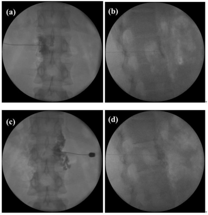
This diagnostic fluoroscopy series illustrates a celiac plexus block (CPB) procedure performed on a patient with resistant hypertension. The image set consists of four panels showcasing a bilateral paravertebral posterior approach. Panels (a) and (c) are anteroposterior (AP) views showing the needle tip positioned adjacent to the L1 vertebral body. In these views, radiopaque contrast material is visualized spreading in a characteristic diffuse, cloud-like pattern prevertebrally, confirming correct needle placement for the injection of botulinum toxin. Panels (b) and (d) provide lateral views, demonstrating the needle's depth and its position relative to the anterior aspect of the vertebral column. The contrast distribution in the lateral views appears as a hazy opacification anterior to the lumbar vertebrae. These images demonstrate a pain management and interventional radiology technique used to target the sympathetic nervous system for the treatment of essential hypertension that is refractory to pharmacological and renal denervation therapies.
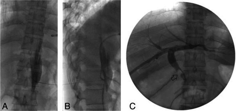
This composite of three fluoroscopy images demonstrates interventional radiology procedures in a patient with biliary obstruction. Images A and B show a celiac plexus block (CPB) using a posterior retrocrural approach at the T12-L1 level. The anteroposterior view (A) shows a bent tip needle positioned lateral to the vertebral column, while the lateral view (B) confirms the needle's trajectory and depth toward the retrocrural space, posterior to the diaphragmatic crus. Image C is a posteroanterior fluoroscopic view of a percutaneous transhepatic biliary drainage (PTBD) and tract dilatation procedure. Contrast media opacifies the intrahepatic and extrahepatic biliary tree, revealing a clear filling defect (indicated by an arrow) in the common bile duct (CBD). This defect represents a 1-cm CBD stone causing proximal obstruction. The images illustrate the combined use of anesthetic nerve blocks to manage pain during invasive hepatobiliary interventions for acute cholecystitis and choledocholithiasis.
stellate ganglion anatomy cervicothoracic sympathetic block ultrasound
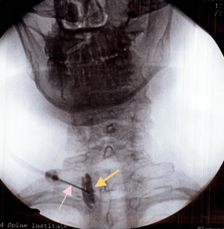
This diagnostic fluoroscopic image in an anteroposterior (AP) view captures a right-sided stellate ganglion block procedure in the lower cervical spine region. The bony anatomy visible includes the base of the skull, the mandible, and the cervical vertebrae from C1 down to the cervicothoracic junction. A radiopaque linear needle or catheter (indicated by a pink arrow) is seen approaching from a lateral-to-medial direction, with its tip positioned at the level of the C6-C7 vertebral interface. Adjacent to the tip of the needle, a localized collection of radiopaque contrast medium (indicated by a yellow arrow) is visible, appearing as an irregular, elongated vertical density lateral to the vertebral bodies. This contrast pattern confirms the appropriate needle tip placement within the prevertebral fascia for the sympathetic block. The image serves as an educational example of interventional pain management techniques, specifically demonstrating fluoroscopic guidance and contrast confirmation during a cervical sympathetic nerve block for conditions such as complex regional pain syndrome (CRPS).
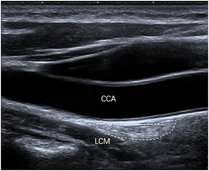
This longitudinal diagnostic ultrasound image illustrates the anatomy of the cervical sympathetic chain, specifically focusing on the stellate ganglion (SG). The stellate ganglion is highlighted by a dashed white outline, demonstrating a characteristic oval shape. Visually, the ganglion exhibits marked hyperechogenicity relative to the adjacent musculature. Anatomical landmarks are labeled for spatial orientation: the Common Carotid Artery (CCA) appears as an anechoic (black) lumen situated anterior to the ganglion, while the Longus Colli Muscle (LCM) is positioned immediately posterior to the ganglion. The image serves as an educational reference for identifying sympathetic nervous system structures in the neck, emphasizing the relationship between vascular and muscular planes in regional anesthesia or pain management procedures. The hyperechoic appearance and ill-defined margins are key sonographic features for identifying the SG within the prevertebral fascia.
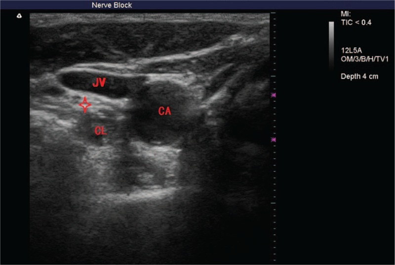
**Imaging Modality:** Ultrasound (B-mode ultrasonography) **Anatomical Region:** Cervical spine region (C6–C7 level), transverse view. **Key Landmarks and Findings:** The image displays the anatomical landmarks relevant for a stellate ganglion nerve block. Key vascular structures include the anechoic, pulsatile common carotid artery (CA) and the partially compressible internal jugular vein (JV). Deep to the prevertebral fascia, the longus colli muscle (CL) is visible as a hypoechoic structure situated anterior to the transverse process. The stellate ganglion (cervicothoracic ganglion) is identified as a small, oval, hypoechoic neural structure, marked with a red star, located medial to the carotid artery and superficial to the longus colli muscle. The image demonstrates the relationship between the sympathetic chain and the overlying prevertebral fascia, providing a target for ultrasound-guided regional anesthesia. **Clinical Context:** This ultrasonogram is utilized for procedural guidance in a nerve block, specifically to ensure precise needle placement and to avoid accidental puncture of adjacent vascular structures such as the carotid artery or vertebral artery.
"celiac plexus block" AND pain cancer
"stellate ganglion block" AND indications
"celiac plexus neurolysis" OR "coeliac plexus block"
"stellate ganglion block" AND sympathetic
BLOCK 1: COELIAC (CELIAC) PLEXUS — ANATOMY, INDICATIONS AND COMPLICATIONS
1. DEFINITION
- The coeliac plexus is the largest autonomic plexus in the body, formed by a dense network of pre- and post-ganglionic sympathetic nerve fibres and visceral afferent fibres surrounding the coeliac trunk at the level of the T12–L1 vertebra
- Coeliac plexus block (CPB): Injection of local anaesthetic or neurolytic agent around the coeliac plexus to interrupt visceral afferent pain transmission from the upper abdominal organs
- Coeliac plexus neurolysis (CPN): Permanent ablation of the coeliac plexus using ethanol (50–100%) or phenol (6–10%) for cancer pain
Exam Tip: Distinguish between block (LA — reversible; for acute/chronic benign pain) and neurolysis (ethanol/phenol — permanent; for cancer pain). Examiners frequently ask this.
2. ANATOMY OF THE COELIAC PLEXUS
2.1 Formation
COELIAC PLEXUS FORMATION:
━━━━━━━━━━━━━━━━━━━━━━━━
Preganglionic sympathetic fibres from:
  T5 → T12 (greater splanchnic nerve: T5–T9)
  T10 → T11 (lesser splanchnic nerve)
  T12 (least splanchnic nerve)
        ↓ Pass through diaphragm (aortic hiatus)
  COELIAC GANGLIA (2 semi-lunar ganglia)
        ↓ Post-ganglionic fibres
  COELIAC PLEXUS (network around coeliac trunk)
        ↓
  Visceral organ innervation
2.2 Composition
| Component | Description |
|---|---|
| Coeliac ganglia | 2 irregular, semilunar ganglia — R and L, straddling the coeliac trunk |
| Greater splanchnic nerves | T5–T9 preganglionic sympathetics — pierce diaphragmatic crura |
| Lesser splanchnic nerves | T10–T11 |
| Least splanchnic nerve | T12 |
| Visceral afferent fibres | Pain fibres from upper abdominal viscera (travel with splanchnic nerves) |
2.3 Location and Relations
| Relation | Structure |
|---|---|
| Level | T12–L1 (vertebral body level) |
| Anterior | Coeliac trunk origin, aorta, inferior vena cava (R side), portal vein |
| Posterior | Diaphragmatic crura (at T12), bodies of T12 and L1 vertebrae |
| Superior | Diaphragm |
| Lateral | Adrenal glands, kidneys, aorta |
| Inferior | Superior mesenteric artery origin |
| The ganglia are: | Retroperitoneal, prevertebral, anterior to the aorta at the L1 level |
Viva Pearl: The coeliac plexus lies anterior to the aorta and anterior to the crura of the diaphragm at L1. The right ganglion is more medial (posterior to the IVC), and the left ganglion is lateral to the aorta. This asymmetry is clinically important for needle placement.
2.4 Visceral Organs Innervated
| Organ | Coverage |
|---|---|
| Stomach | ✓ |
| Liver and gallbladder | ✓ |
| Spleen | ✓ |
| Pancreas | ✓ (primary target) |
| Small intestine | ✓ (to mid-transverse colon) |
| Kidneys and adrenals | ✓ |
| Descending colon | ✗ (inferior mesenteric/hypogastric plexus) |
| Pelvic organs | ✗ |
2.5 Splanchnic Nerves — Distinct from Plexus
- The splanchnic nerves carry preganglionic fibres before synapsing in the coeliac ganglia
- Splanchnic nerve block = more proximal (at T12, retrocrural) → blocks fibres before synapse → broader, more reliable coverage
- vs. Coeliac plexus block = blocks fibres after synapse (at L1, antecrural) → targets postsynaptic plexus
3. SURGICAL AND CLINICAL INDICATIONS
3.1 Coeliac Plexus Block (LA — Reversible)
| Category | Indication |
|---|---|
| Cancer pain | Diagnostic/prognostic before neurolysis |
| Chronic pancreatitis | Abdominal pain — short-term relief (EUS-guided) |
| Acute pancreatitis | Visceral pain management (adjunct) |
| Post-operative | Visceral pain after upper abdominal surgery |
| Diagnostic | Confirm visceral origin of pain |
3.2 Coeliac Plexus Neurolysis (Ethanol/Phenol — Permanent)
| Category | Indication |
|---|---|
| Pancreatic cancer | Primary indication — unresectable pancreatic adenocarcinoma |
| Gastric cancer | Upper abdominal visceral pain |
| Hepatobiliary cancer | Liver, gallbladder, bile duct malignancy |
| Renal cell carcinoma | Retroperitoneal visceral pain |
| ERAS + oncology | Opioid-sparing in terminal cancer |
Exam Tip: CPN is recommended in unresectable pancreatic cancer as it reduces opioid consumption and improves quality of life. It is not first-line for chronic pancreatitis — LA block may provide short-term relief but neurolysis is avoided in benign conditions.
4. APPROACHES TO COELIAC PLEXUS BLOCK
Classification of Approaches
COELIAC PLEXUS BLOCK APPROACHES
              |
    __________|__________
    |                   |
POSTERIOR (Classic)    ANTERIOR
    |                   |
Retrocrural approach   EUS-guided
Anterocrural approach  CT-guided (anterior)
Bilateral paravertebral
Transdiscal approach
4.1 Posterior Retrocrural Approach (Classic)
Patient Position
- Prone with pillow under abdomen to flex spine
Surface Anatomy Landmarks
- T12 spinous process
- A point 7–8 cm lateral to midline bilaterally (at T12 level)
- Target: Anterolateral body of L1 vertebra behind the diaphragmatic crura
Technique (Fluoroscopy-Guided)
STEP 1: Mark T12 spinous process and 7–8 cm lateral bilaterally
STEP 2: Insert 20–22G, 15–20 cm spinal needle bilaterally
         at 45° medially and 15° cephalad
STEP 3: Contact body of T12 vertebra → walk needle laterally
STEP 4: Advance needle anterior to T12/L1 body
         (retrocrural space — posterior to diaphragmatic crura)
STEP 5: Fluoroscopy confirmation: AP + LATERAL views
STEP 6: Contrast injection (3–5 mL) — confirm prevertebral spread,
         no vascular uptake
STEP 7: TEST DOSE — 3 mL LA (check for intravascular injection)
STEP 8: LA block: 25–50 mL 0.25% bupivacaine bilaterally (12.5 mL/side)
         OR Neurolysis: 10–20 mL 50–100% ethanol per side (total 20–40 mL)
         (Preceded by 5 mL LA for comfort)
4.2 Anterocrural (Transaortic / Transdiscal) Approach
- Needle advanced anterior to diaphragmatic crura (antecrural space)
- Transaortic approach: Single needle passed through aorta (deliberate!) to reach anterior aortic plane — controversial, higher risk
- Transdiscal: Needle passed through T12–L1 disc — risk of discitis
4.3 Anterior Approaches
| Approach | Guidance | Advantage |
|---|---|---|
| EUS-guided CPB/CPN | Endoscopic US | Least invasive; direct visualisation of celiac trunk and ganglia; safest route for cancer patients |
| CT-guided CPB | CT scan | Precise needle placement; real-time confirmation |
| US-guided (transabdominal) | Abdominal US | Bedside, no radiation; may be limited by bowel gas |
Viva Pearl: EUS-guided CPN has become the preferred route in most cancer patients as it avoids the risks of posterior approach (no paraplegia, no pneumothorax), allows direct visualisation of the celiac ganglia, and can be performed simultaneously with staging/diagnostic endoscopy.
Fluoroscopy Appearance (What to Draw in Exam)
5. LOCAL ANAESTHETICS AND NEUROLYTIC AGENTS
| Agent | Use | Volume | Concentration | Duration |
|---|---|---|---|---|
| Bupivacaine | CPB (LA) | 20–30 mL bilateral | 0.25–0.5% | 8–24 h |
| Ropivacaine | CPB (LA) | 20–30 mL | 0.375–0.5% | 8–20 h |
| Absolute ethanol | CPN (neurolysis) | 20–40 mL bilateral (10–20 mL/side) | 50–100% | Permanent |
| Phenol | CPN (alternative) | 10–20 mL | 6–10% | Permanent |
| Contrast dye | Confirmation | 3–5 mL | Iohexol | — |
- Pre-neurolysis: Always inject 5 mL 0.25% bupivacaine before ethanol to reduce neurolytic burning pain
- Post-injection: Aspirate blood before each increment; test dose mandatory
6. PATIENT PREPARATION
- Informed written consent (including neurolysis risks — paraplegia, impotence)
- IV access, monitoring (ECG, SpO2, NIBP)
- Coagulation screen — INR/PT, aPTT, platelets (retroperitoneal space, non-compressible)
- Imaging: Pre-procedure CT scan to assess vessel anatomy, tumour relation to plexus
- Antibiotic prophylaxis for transdiscal or EUS-guided approach
- Sedation/analgesia: midazolam + fentanyl IV
- Fluids: IV preloading with 500 mL crystalloid (anticipate sympatholysis → hypotension)
- Vasopressors available
7. ASSESSMENT OF BLOCK SUCCESS
| Parameter | Assessment |
|---|---|
| Pain relief | VAS/NRS score reduction ≥ 50% within 24–48 h |
| Sympatholysis | Warm legs, skin flushing, nasal congestion |
| Orthostatic hypotension | ↓ BP on standing |
| Diarrhoea | Increased bowel motility (parasympathetic unopposed) |
| Duration | LA block: hours to days; Neurolysis: weeks to months |
8. COMPLICATIONS
Classification
COMPLICATIONS OF COELIAC PLEXUS BLOCK
                |
    ____________|_____________
    |           |             |
 IMMEDIATE   DELAYED     SERIOUS/RARE
    |           |             |
Hypotension  Diarrhoea    Paraplegia
Pain at site  Backache    Anterior spinal
Haematuria    Sexual dys  artery syndrome
              function    Aortic injury
                         Pneumothorax
                         Retroperitoneal
                         haematoma
Detailed Complications Table
| Complication | Incidence | Mechanism | Prevention | Management |
|---|---|---|---|---|
| Hypotension | 10–40% (most common) | Splanchnic sympatholysis → vasodilatation + visceral pooling | IV fluid preload; vasopressors on standby | Fluids; phenylephrine/ephedrine |
| Diarrhoea | 44–60% | Unopposed parasympathetic → increased bowel motility | Counsel patient | Loperamide; usually self-limiting (24–72 h) |
| Local pain/burning | Very common with ethanol | Neurolytic spread to somatic nerves | Bupivacaine pre-injection | Analgesia |
| Retroperitoneal haematoma | Rare | Needle injury to aorta, IVC, lumbar vessels | Imaging guidance; coagulation check | Conservative; surgery if expanding |
| Pneumothorax | < 1% | Needle tip too high (T11–T12 level) | Fluoroscopic confirmation of level | O2; chest drain if large |
| Paraplegia / Anterior spinal artery syndrome | < 0.2% (most feared) | Ethanol spreads to Artery of Adamkiewicz (T8–L1) → anterior spinal artery occlusion | CT guidance; small incremental volumes; avoid intravascular injection; never inject against resistance | Steroids; emergency neurosurgery consult — poor prognosis |
| Intravascular injection | 1–4% | Needle in aorta, IVC, intercostal artery | Test dose + aspiration + contrast | LAST protocol |
| Subarachnoid injection | Rare | Needle through epidural/intrathecal route | Fluoroscopy and contrast confirmation | Resuscitation |
| Sexual dysfunction | ~5% males | Hypogastric/lumbar sympathetic involvement | Careful technique | Counsel; usually reversible |
| Infection/abscess | Rare | Haematogenous or direct needle track | Asepsis; antibiotic prophylaxis | Antibiotics; drainage |
| Discitis | Rare (transdiscal approach) | Direct inoculation | Avoid transdiscal unless necessary | Antibiotics |
| Nephrotoxicity | Rare | Ethanol/phenol proximity to renal vessels | CT localisation | Supportive |
Exam Tip — Most Feared Complication: Paraplegia from anterior spinal artery syndrome (Adamkiewicz artery injury) is the most catastrophic complication of CPN. The Artery of Adamkiewicz arises at T8–L1 in 85% of cases — directly in the field of injection. Prevention: use CT or fluoroscopic guidance, contrast confirmation, incremental injection, never inject against resistance.
9. EVIDENCE AND RECENT ADVANCES (2024–2026)
Key Evidence
- Lu et al. Meta-analysis, Pain Physician 2024 [PMID: 38285023]: CPN vs. splanchnic nerve neurolysis for abdominal cancer pain (n=359) — splanchnic nerve neurolysis provided superior pain relief with comparable safety; CPN remains widely used but SNN may be preferred when technically feasible
- Xuan et al. Meta-analysis 2024 [PMID: 38552386]: EUS-guided approaches for pancreatic cancer — effective pain relief with favourable safety profile
- 2024 Advances:
- EUS-guided celiac ganglia neurolysis (CGN): Direct injection into identified ganglia under EUS — superior to plexus-level injection
- Radiofrequency ablation (RFA) of coeliac plexus: Emerging as alternative to neurolysis — precise, repeatable
- CT-guided robotic-assisted CPN — research phase
- Cryoablation of coeliac plexus — emerging technique
- Bilateral simultaneous EUS approach — novel technique for better coverage
- ERAS integration: CPN at time of pancreatic surgery (Whipple procedure) — opioid-free intraoperative and postoperative analgesia
10. CURRENT GUIDELINES
| Organisation | Recommendation |
|---|---|
| ESRA 2023 | EUS-guided CPN/CGN is the preferred approach in cancer patients; imaging guidance mandatory |
| ASRA/APS | CPN recommended for unresectable pancreatic cancer; evidence insufficient for chronic pancreatitis neurolysis |
| WHO Analgesic Ladder | CPN/CPN at Step 3 — interventional approach after opioids |
| ESAIC 2024 | EUS-CGN preferred over traditional fluoroscopic CPN; fluoroscopy mandatory if posterior approach used |
11. CLINICAL PEARLS
- "Visceral pain = coeliac plexus" — any upper abdominal visceral pain (pancreatic, hepatobiliary, renal) is potentially amenable to CPB/CPN
- Hypotension in 10–40% — always preload with 500 mL IV crystalloid before the procedure
- Always inject bupivacaine 5 mL before ethanol — reduces neurolytic burning pain
- Never inject against resistance — high risk of intraneural injection and paraplegia
- Test dose 3 mL LA + aspiration before every injection — essential
- Lateral fluoroscopic view is mandatory — AP alone cannot confirm anterior placement; must see contrast anterior to vertebral body
- EUS-guided approach is preferred in cancer patients — direct ganglia visualisation, avoids paraplegia risk, no radiation
- Diarrhoea is expected and normal for 24–72 h — counsel patients beforehand
- The right ganglion lies posterior to the IVC — right-sided approaches have higher IVC puncture risk
- Retrocrural vs. anterocrural: Retrocrural = greater/lesser splanchnic level (more reliable for pancreatic pain); Anterocrural = coeliac plexus level (broader coverage)
- LA block for chronic pancreatitis gives only short-term relief (4–8 weeks) — not a definitive treatment
- Ethanol concentration > 50% necessary for permanent neurolysis; phenol 6–10% is an alternative with less burning but slower onset
- Splanchnic nerve block at T12 may be preferred over CPN for better coverage and lower paraplegia risk
- Always obtain coagulation status — this is a deep non-compressible procedure; LMWH therapeutic must be withheld for 24 hours
12. COMMON VIVA QUESTIONS
- Block uses LA (bupivacaine/ropivacaine) — reversible, diagnostic; Neurolysis uses ethanol 50–100% or phenol 6–10% — permanent ablation for cancer pain
- Hypotension (10–40%) from splanchnic sympatholysis; diarrhoea (44–60%) from unopposed parasympathetics
- Paraplegia from anterior spinal artery syndrome (Artery of Adamkiewicz at T8–L1)
- The dominant medullary artery supplying the anterior spinal cord; arises from the aorta at T8–L1 in 85% of individuals; injury during CPN → anterior spinal cord ischaemia → paraplegia
- Retrocrural: needle tip behind diaphragmatic crura at T12 → targets splanchnic nerves; Anterocrural: needle tip anterior to crura at L1 → targets coeliac plexus ganglia
- Direct visualisation of coeliac ganglia; avoids posterior approach complications (paraplegia, pneumothorax, haematoma); can be combined with staging procedure; better targeting
- Splanchnic nerve block/neurolysis targets preganglionic fibres at T12 BEFORE they synapse in the coeliac ganglia; Lu et al. 2024 meta-analysis showed superior pain relief; reduces risk to major vessels
- Fluoroscopy: AP (bilateral spread at L1) + Lateral (contrast anterior to vertebral body); aspirate before injection; test dose; no vascular uptake on contrast
BLOCK 2: STELLATE GANGLION BLOCK (SGB)
1. DEFINITION
- Stellate ganglion (cervicothoracic ganglion): A sympathetic ganglion formed by the fusion of the inferior cervical ganglion (C8) and the first thoracic ganglion (T1) in approximately 80% of individuals
- Stellate ganglion block (SGB): Injection of local anaesthetic anterior to the stellate ganglion to produce ipsilateral cervicothoracic sympathectomy — blocking sympathetic supply to the head, neck, upper limb, heart, and ipsilateral thorax
- Named "stellate" (Latin: star-shaped) because of its characteristic star-like morphology
2. ANATOMY OF THE STELLATE GANGLION
2.1 Formation and Location
| Parameter | Detail |
|---|---|
| Formation | Fusion of inferior cervical ganglion (C8) + 1st thoracic ganglion (T1) — in 80% |
| When NOT fused | Separate inferior cervical and T1 ganglia — in 20% |
| Location | Anterior to the transverse process of C7 and head of 1st rib |
| Vertebral level | C7–T1 junction |
| Size | 2.5 cm long × 1 cm wide × 0.5 cm thick (variable) |
| Shape | Irregular, star-shaped |
2.2 Anatomical Relations (Key for Block Safety)
RELATIONS OF STELLATE GANGLION:
────────────────────────────────────────────────
ANTERIOR:   Common carotid artery, internal jugular vein,
            subclavian artery (lower), origin of vertebral artery
POSTERIOR:  Longus colli muscle, prevertebral fascia, C7 transverse process
MEDIAL:     Trachea, oesophagus, thoracic duct (left side)
LATERAL:    Scalene muscles, brachial plexus
SUPERIOR:   Middle cervical ganglion (C5–C6)
INFERIOR:   T2 thoracic ganglion, pleural apex
────────────────────────────────────────────────
DANGER STRUCTURES:
• Vertebral artery — passes through foramen transversarium at C6
  (RISK AT C7 LEVEL — no foramen transversarium protection)
• Carotid artery — medial to SCM
• Internal jugular vein — lateral to carotid
• Phrenic nerve — on anterior scalene
• Recurrent laryngeal nerve — in tracheoesophageal groove
• Brachial plexus — lateral
• Pleural apex — below (risk of pneumothorax)
• Thoracic duct — on left side
Exam Tip — Critical Safety Point: The vertebral artery is NOT protected at C7 (no foramen transversarium at C7). This is why injection at C6 (Chassaignac tubercle) is preferred over C7 — at C6, the vertebral artery is within the foramen transversarium and less accessible to the needle.
2.3 Sympathetic Supply Carried by Stellate Ganglion
| Region Innervated | Clinical Implication |
|---|---|
| Head and neck | Horner syndrome when blocked |
| Upper extremity (ipsilateral) | Vasodilatation, increased blood flow, warmth |
| Heart | Reduced chronotropy (important for arrhythmia indications) |
| Ipsilateral arm | Sudomotor, vasomotor |
| Lungs (ipsilateral) | Bronchodilatation |
Viva Pearl: The stellate ganglion carries fibres from C8–T4 (with cardiac accelerator fibres from T1–T4). A left SGB reduces left cardiac sympathetic tone — important for long QT syndrome-related arrhythmia treatment.
3. INDICATIONS FOR STELLATE GANGLION BLOCK
3.1 Established/Classic Indications
| Category | Indication |
|---|---|
| Pain (sympathetically-maintained) | CRPS type I and II (upper extremity) — primary indication |
| Vascular | Vascular insufficiency of the upper extremity, Raynaud's disease/phenomenon |
| Herpes zoster | Herpes zoster of head, neck, or upper extremity — acute phase (reduce allodynia, prevent PHN) |
| Post-herpetic neuralgia | PHN of face/neck |
| Phantom limb pain | Upper extremity |
| Hyperhidrosis | Facial and upper extremity hyperhidrosis |
| Vascular headache | Cluster headache (adjunct) |
| Frostbite | Upper extremity |
3.2 Cardiac Indications (Novel — Growing Evidence)
| Indication | Detail |
|---|---|
| Ventricular arrhythmias / VT storm | Left SGB reduces cardiac sympathetic tone; emergency use in refractory VT/VF storm |
| Congenital long QT syndrome | Left SGB preferred — reduces left stellate sympathetic dominance → shortens QT |
| Catecholaminergic polymorphic VT (CPVT) | Left SGB as bridge to definitive treatment |
| Post-MI arrhythmia | Sympathetic storm management |
| Subarachnoid haemorrhage (SAH) — vasospasm | Brenner et al. Systematic Review, World Neurosurg 2024 [PMID: 38042290] — SGB reduces cerebral vasospasm after SAH |
3.3 Novel/Emerging Indications (2024–2026)
| Indication | Evidence Level |
|---|---|
| Hot flushes in breast cancer survivors | High evidence (RCT) — significant reduction |
| PTSD (Post-traumatic stress disorder) | Emerging evidence — modulates sympathetic hyperactivity |
| Menopausal vasomotor symptoms | Growing evidence |
| Long COVID autonomic dysfunction | Pilot studies 2023–2025 |
| Perioperative cardiac protection | Tsai et al. BJA 2026 [PMID: 41027820] — review of perioperative SGB utility |
Viva Pearl (2026): Tsai et al. published a narrative review in British Journal of Anaesthesia (2026) on SGB in perioperative practice — highlighting cardiac arrhythmia management, cancer survivor hot flushes, and PTSD as key emerging indications. This is highly likely to appear in viva.
4. TECHNIQUES FOR STELLATE GANGLION BLOCK
4.1 Landmark/Paratracheal Technique (Classical)
Patient Position
- Supine, neck slightly extended, mouth slightly open (relaxes SCM)
- Head neutral or slightly rotated to contralateral side
Landmarks
- Cricoid cartilage = C6 level — primary landmark
- Chassaignac's tubercle = anterior tubercle of C6 transverse process — can be palpated 3 cm lateral to midline at C6
- SCM medial border — retract laterally
- Injection point: Medial border of SCM at cricoid level (C6)
Technique
STEP 1: Palpate cricoid cartilage (C6 level)
STEP 2: Place 2 fingers LATERAL to trachea, medial to SCM
         Retract the carotid sheath LATERALLY
STEP 3: Insert 22G, 4–5 cm needle PERPENDICULAR to skin
STEP 4: Contact C6 transverse process (Chassaignac tubercle)
         at approximately 2–3 cm depth
STEP 5: Withdraw needle 2–3 mm (off periosteum)
STEP 6: TWO-PLANE ASPIRATION (rotate syringe 90° and re-aspirate)
STEP 7: 1 mL TEST DOSE — exclude intravascular/subarachnoid injection
STEP 8: Inject 5–10 mL LA in incremental aliquots (2 mL each)
STEP 9: Keep patient supine for 5–10 minutes
STEP 10: Assess Horner syndrome (success marker)
Viva Pearl: The "two-plane aspiration" technique (aspirate in standard plane → rotate syringe 90° → re-aspirate) is mandatory because the vertebral artery runs perpendicular to the needle — a single aspiration may miss intravascular placement.
4.2 Ultrasound-Guided Technique (Preferred — Gold Standard)
Setup
- Patient: Supine, neck extended, head turned contralateral
- Probe: High-frequency linear (15–6 MHz), transverse orientation at C6 level
Sonoanatomy at C6 Level
ULTRASOUND ANATOMY (Transverse view at C6):
────────────────────────────────────────────────────
[Skin / SCM (oval)]
[Carotid artery (anechoic, pulsatile)]
[Internal jugular vein (compressible, lateral to CA)]
[Anterior scalene muscle (lateral)]
[C6 TRANSVERSE PROCESS — hyperechoic with acoustic shadow]
  └ Chassaignac tubercle (anterior tubercle) visible
[LONGUS COLLI MUSCLE — hypoechoic, posterior]
[TARGET: Anterior surface of longus colli / below prevertebral fascia]
────────────────────────────────────────────────────
VERTEBRAL ARTERY — within foramen transversarium (not seen at C6 surface)
Needle Technique (US-Guided)
| Step | Action |
|---|---|
| 1 | Place probe transverse at C6 level |
| 2 | Identify carotid artery, IJV, C6 TP (Chassaignac tubercle), longus colli muscle |
| 3 | Apply colour Doppler — identify carotid, vertebral artery (in transverse foramen), inferior thyroid artery |
| 4 | Insert 22G 4–5 cm needle in-plane, lateral to medial |
| 5 | Target: Anterior surface of longus colli, deep to prevertebral fascia medial to Chassaignac tubercle |
| 6 | Aspirate × 2 planes; inject 1 mL test dose |
| 7 | Inject 4–5 mL LA observing spread under prevertebral fascia |
| 8 | Watch for Horner syndrome within 5–10 min |
Exam Tip: The target in US-guided SGB is anterior to the longus colli muscle, medial to C6 transverse process — the LA should be seen spreading under the prevertebral fascia (not infiltrating the muscle).
5. DRUG DOSES
| Drug | Concentration | Volume | Onset | Duration |
|---|---|---|---|---|
| Bupivacaine | 0.25% | 5–10 mL | 15–20 min | 8–18 h |
| Ropivacaine | 0.2–0.375% | 5–10 mL | 10–15 min | 8–14 h |
| Lidocaine | 1–1.5% | 5–10 mL | 3–5 min | 2–3 h |
| Mepivacaine | 1% | 5–10 mL | 5–10 min | 3–6 h |
- Volume < 5 mL → may not reliably reach stellate ganglion (which lies at C7–T1)
- Volume > 10 mL → increased spread to adjacent structures (phrenic nerve, recurrent laryngeal nerve, epidural space)
- Optimal volume: 5–10 mL at C6 level (LA diffuses caudally to reach the ganglion at C7–T1)
6. ASSESSMENT OF SUCCESSFUL BLOCK — HORNER SYNDROME
Horner Syndrome (Oculosympathetic Paresis) — Mandatory Confirmation
| Sign | Description |
|---|---|
| Ptosis | Partial drooping of upper eyelid (Müller muscle paralysis) |
| Miosis | Constriction of pupil (dilator pupillae muscle paralysis) |
| Enophthalmos | Apparent recession of eyeball |
| Anhidrosis | Loss of sweating on ipsilateral face |
| Nasal congestion | Ipsilateral — sympathetic vasoconstriction lost |
- Warm, dry ipsilateral upper extremity
- Increased skin temperature of ipsilateral arm/hand (best objective measure)
- Nasal stuffiness
- Conjunctival injection (ipsilateral)
Exam Tip: Horner syndrome is the clinical endpoint confirming successful SGB. All 4 signs (ptosis, miosis, enophthalmos, anhidrosis) are called "PMEA" mnemonic.
7. COMPLICATIONS
| Complication | Mechanism | Incidence | Prevention | Management |
|---|---|---|---|---|
| Intravascular injection (vertebral or carotid artery) | Needle in vessel | Most common serious complication | US guidance; aspiration; test dose | LAST protocol; Intralipid 20% |
| Recurrent laryngeal nerve block | LA spread medially | Common (5–10%) | Limit volume; US guidance | Reassurance; resolves in hours; watch for bilateral |
| Phrenic nerve block | LA spread to anterior scalene | ~10–20% | Limit volume ≤ 10 mL; US | O2; PPV if symptomatic |
| Brachial plexus block | LA spread laterally | Occasional | US guidance; medial needle placement | Reassurance |
| Horner syndrome | Cervical sympathetic block | Expected outcome (100% if successful) | — | Reassure (expected) |
| Subarachnoid injection | Needle through dural sleeve of spinal root | Rare but catastrophic | C6 preferred over C7; aspiration test | Resuscitation; total/high spinal |
| Epidural injection | LA spread medially | Rare | Aspiration; test dose; contrast confirmation | Supportive |
| Oesophageal puncture | Medial needle deviation | Rare | US guidance | Antibiotics |
| Pneumothorax | Needle below clavicle (C7 approach) | Rare | C6 preferred; US | O2; chest drain |
| Haematoma | Carotid/vertebral/IJV puncture | 1–3% | Aspiration; US Doppler | Direct pressure; observation |
| Seizures | Intravascular LA (vertebral artery) | Rare | Test dose; aspiration; US | Airway; benzodiazepine |
| Bilateral Horner/bilateral phrenic block | Bilateral SGB | Contraindicated | Never perform bilateral simultaneously | Ventilatory support |
Critical Safety Point: Even 1 mL of LA inadvertently injected into the vertebral artery causes immediate generalised seizures (artery supplies brainstem/cerebellum directly). Always use test dose + two-plane aspiration. US guidance has dramatically reduced this risk.
8. CONTRAINDICATIONS
| Absolute | Relative |
|---|---|
| Patient refusal | Contralateral phrenic/recurrent laryngeal nerve palsy |
| Infection at injection site | Coagulopathy (anticoagulated patient) |
| Bilateral blocks (respiratory failure, vocal cord paralysis) | Severe COPD (phrenic nerve risk) |
| Allergy to LA | Glaucoma (miosis from Horner may interfere with monitoring) |
9. RECENT ADVANCES AND EVIDENCE (2024–2026)
| Topic | Evidence |
|---|---|
| SGB for VT storm | Established indication; ACLS supplement; left SGB preferred for cardiac arrhythmia |
| SGB for SAH vasospasm | Brenner et al. World Neurosurg 2024 [PMID: 38042290] — systematic review confirms SGB reduces vasospasm incidence after SAH; mechanism: blocks sympathetically mediated cerebrovascular spasm |
| SGB for CRPS | Tian et al. Pain Physician 2024 [PMID: 38805523] — meta-analysis confirms short-term significant pain relief in upper extremity CRPS; effect size moderate; adjunct to PT |
| SGB anatomy review 2025 | Rusu et al. Diagnostics 2025 [PMID: 41300935] — comprehensive review of anatomy and clinical significance; highlights anatomical variability (fusion vs non-fusion, C7 vs C8 level) |
| SGB in perioperative practice 2026 | Tsai et al. BJA 2026 [PMID: 41027820] — narrative review; endorses SGB for cardiac arrhythmia management, cancer survivor hot flushes, and PTSD in perioperative setting |
| US-guided high-volume vs. low-volume | 5 mL vs. 10 mL at C6 — equivalent Horner success; lower risk with 5 mL (fewer side effects) |
| Pulsed radiofrequency of stellate ganglion | Emerging as longer-lasting alternative to repeated LA blocks for CRPS/PHN |
| AI-assisted ultrasound for SGB | Automated identification of longus colli and carotid artery — prototype systems in trials (2025) |
10. COMPARISON: COELIAC PLEXUS BLOCK vs. STELLATE GANGLION BLOCK
| Feature | Coeliac Plexus Block | Stellate Ganglion Block |
|---|---|---|
| Ganglion type | Prevertebral sympathetic (paired) | Paravertebral cervicothoracic sympathetic |
| Level | T12–L1 | C7–T1 |
| Primary indication | Pancreatic cancer / chronic pancreatitis | CRPS upper extremity / VT arrhythmia |
| Most feared complication | Paraplegia | Vertebral artery injection/seizures |
| Most common complication | Hypotension | Horner syndrome (expected) |
| Neurolytic agent | Ethanol 50–100% / Phenol 6–10% | Not used neurolytically (LA only) |
| Guidance | Fluoroscopy / CT / EUS | US (preferred) / Fluoroscopy |
| Success marker | Pain relief + diarrhoea + hypotension | Horner syndrome |
| Volume | 20–40 mL bilateral | 5–10 mL unilateral |
| Cardiac effects | Splanchnic sympatholysis → hypotension | Reduced heart rate/arrhythmia (left SGB) |
| Bilateral | Used bilaterally routinely | Never perform bilaterally |
11. CLINICAL PEARLS — STELLATE GANGLION BLOCK
- The C6 approach is safer than C7 — at C6, the vertebral artery is protected within the foramen transversarium; at C7, it is exposed
- Retract the carotid sheath laterally before needle insertion (landmark technique) — reduces risk of carotid/IJV puncture
- Two-plane aspiration is mandatory — the vertebral artery runs perpendicular to the needle; single-plane aspiration can miss intravascular placement
- Horner syndrome = block success — if no Horner after 20 minutes, the block has failed
- 5–10 mL volume at C6 is optimal — LA diffuses caudally to reach stellate ganglion at C7–T1 level
- Bilateral SGB is absolutely contraindicated — bilateral phrenic + bilateral recurrent laryngeal = respiratory failure
- Left SGB for cardiac arrhythmia — left stellate carries dominant cardiac sympathetic supply
- PTSD and hot flushes are growing indications — documented in 2024–2026 literature; very likely viva topic
- Even 1 mL of LA into the vertebral artery causes immediate brainstem toxicity/seizure — vigilance is paramount
- Skin temperature rise > 1°C in the ipsilateral arm is the most objective physiological marker of successful sympathectomy
- Pulsed radiofrequency (PRF) of the stellate ganglion provides longer-lasting effect than repeated LA blocks — emerging alternative for CRPS
- The Kuntz nerves (T2–T3) can bypass the stellate ganglion via separate pathways joining the brachial plexus — these are missed by SGB but blocked by axillary block (clinically relevant for upper extremity hyperhidrosis)
12. COMMON VIVA QUESTIONS — STELLATE GANGLION BLOCK
- Fusion of inferior cervical (C8) and first thoracic (T1) sympathetic ganglia in 80% of people; located at C7–T1 junction, anterior to longus colli, posterior to carotid artery, lateral to oesophagus
- At C6, the vertebral artery is within the foramen transversarium and protected; at C7, the vertebral artery is exposed and at higher risk of direct puncture during needle insertion
- Ptosis, miosis, enophthalmos, anhidrosis — from interruption of sympathetic supply to the eye and face. Horner syndrome is the clinical endpoint confirming successful block, as the superior cervical ganglion (innervating the eye) is in the same sympathetic chain
- Bilateral recurrent laryngeal nerve block → bilateral vocal cord paralysis → airway obstruction; bilateral phrenic nerve block → bilateral hemidiaphragmatic paresis → respiratory failure
- The stellate ganglion provides sympathetic innervation to the heart (T1–T4). Left SGB reduces left cardiac sympathetic dominance → reduces triggered arrhythmias → beneficial in long QT syndrome, catecholaminergic VT, and VT storm
- The left stellate ganglion provides dominant sympathetic innervation to the sinoatrial node and ventricular myocardium; left stellate stimulation prolongs QT interval; left SGB specifically reduces this arrhythmogenic drive
- Immediate cerebral/brainstem toxicity — generalised seizures within seconds (the vertebral artery supplies the brainstem directly; even a tiny dose reaches high concentrations instantly)
- Hot flushes in breast cancer survivors; PTSD; menopausal vasomotor symptoms; subarachnoid haemorrhage vasospasm (Brenner et al. 2024); perioperative cardiac arrhythmia management (Tsai et al. BJA 2026)
13. RAPID REVISION BOX
COELIAC PLEXUS & STELLATE GANGLION — ONE PAGE REVISION
━━━━━━━━━━━━━━━━━━━━━━━━━━━━━━━━━━━━━━━━━━━━━━━━━━━━━━
COELIAC PLEXUS:
  Location: T12–L1, anterior to aorta, retroperitoneal
  Formed by: Greater (T5–T9) + Lesser (T10–T11) + Least (T12) splanchnic nn.
  Block (LA): 20–30 mL bupivacaine 0.25%
  Neurolysis: Ethanol 50–100% (10–20 mL/side) | Phenol 6–10%
  Always: 5 mL bupivacaine BEFORE ethanol
  Guidance: Fluoroscopy (AP + LATERAL) | EUS preferred in cancer
  Confirmation: Contrast anterior to vertebral body (lateral view)
  Most common: HYPOTENSION (10–40%) + DIARRHOEA (44–60%)
  Most feared: PARAPLEGIA (Artery of Adamkiewicz, T8–L1)
  Best indication: Unresectable PANCREATIC CANCER

━━━━━━━━━━━━━━━━━━━━━━━━━━━━━━━━━━━━━━━━━━━━━━━━━━━━━━
STELLATE GANGLION:
  Formed by: Inferior cervical (C8) + T1 fusion (80%)
  Location: C7–T1, anterior to longus colli, posterior to carotid
  Relations danger: Vertebral artery (C7 – NO foramen protection!)
                    Carotid artery, IJV, Phrenic, Recurrent laryngeal
  Injection: C6 LEVEL preferred (Chassaignac tubercle)
  Volume: 5–10 mL LA (bupivacaine 0.25% OR ropivacaine 0.2%)
  TWO-PLANE ASPIRATION mandatory
  Success marker: HORNER SYNDROME (Ptosis, Miosis, Enophthalmos, Anhidrosis)
  Mnemonic PMEA: Ptosis Miosis Enophthalmos Anhidrosis
  Best US target: Anterior to longus colli, medial to Chassaignac tubercle

  INDICATIONS:
    Classic: CRPS upper limb | Herpes zoster | Raynaud | Hyperhidrosis
    Cardiac: VT storm | Long QT syndrome (LEFT SGB)
    Novel 2024-26: PTSD | Hot flushes | SAH vasospasm | Perioperative arrhythmia

  COMPLICATIONS:
    Vertebral artery → Immediate seizures (1 mL sufficient)
    Phrenic nerve → Hemidiaphragm paresis
    Recurrent laryngeal → Hoarseness
    Horner → Expected (success sign)
    BILATERAL = CONTRAINDICATED

  RECENT EVIDENCE:
    Tian et al. (Pain Physician 2024): SGB for CRPS — moderate efficacy
    Brenner et al. (World Neurosurg 2024): SGB for SAH vasospasm — promising
    Tsai et al. (BJA 2026): SGB in perioperative practice — narrative review

━━━━━━━━━━━━━━━━━━━━━━━━━━━━━━━━━━━━━━━━━━━━━━━━━━━━━━
KEY NUMBERS:
  CPN ethanol: 10–20 mL/side | 50–100% concentration
  CPB bupivacaine: 0.25% × 20–30 mL bilateral
  SGB volume: 5–10 mL at C6
  CPN most common: Hypotension (10–40%)
  SGB injection: C6 NOT C7 (vertebral artery safety)
━━━━━━━━━━━━━━━━━━━━━━━━━━━━━━━━━━━━━━━━━━━━━━━━━━━━━━
```---

## 📋 UPDATED QUESTION TRACKER

### ✅ DISCUSSED (6 topics)

| # | Topic | Paper Reference | Done |
|---|-------|----------------|------|
| 1 | Brachial Plexus — anatomy, all routes, complications | Sec 15 P1/Q5 | ✅ |
| 2 | Erector Spinae Plane Block | Sec 15 P4/Q4 | ✅ |
| 3 | Serratus Anterior Plane Block | Sec 15 P4 (truncal) | ✅ |
| 4 | Paravertebral Block + Space | Sec 11 P2/Q12 | ✅ |
| 5 | Coeliac Plexus — anatomy, block, indications, complications | Sec 15 P1/Q1; P2/Q6 | ✅ |
| 6 | Stellate Ganglion Block | Sec 15 P1/Q8; P2/Q7 | ✅ |

**53 questions remaining across both sections.**

---

**Key examiner-favourite points covered in both answers:**

**Coeliac Plexus:**
- Splanchnic nerve formation (T5–T12) and the **retrocrural vs anterocrural** distinction
- **Artery of Adamkiewicz (T8–L1)** — the critical paraplegia mechanism
- **Ethanol protocol** — always bupivacaine first, then ethanol
- **EUS-guided CPN** as modern preferred approach
- Hypotension + diarrhoea as expected effects
- Lu et al. 2024 meta-analysis (CPN vs splanchnic neurolysis)

**Stellate Ganglion:**
- **C6 NOT C7** — the single most important safety principle
- **Two-plane aspiration** — mandatory for vertebral artery safety
- **Horner syndrome = PMEA** — the success endpoint
- **Left SGB for cardiac arrhythmia** (long QT, VT storm)
- Emerging indications: PTSD, hot flushes, SAH vasospasm
- Tsai et al. BJA 2026 + Brenner et al. World Neurosurg 2024 — two key 2025–2026 papers

Say **"Next"** or name the next topic when ready.
TAP block, Quadratus lumborum block
TAP block transversus abdominis plane ultrasound abdominal wall layers
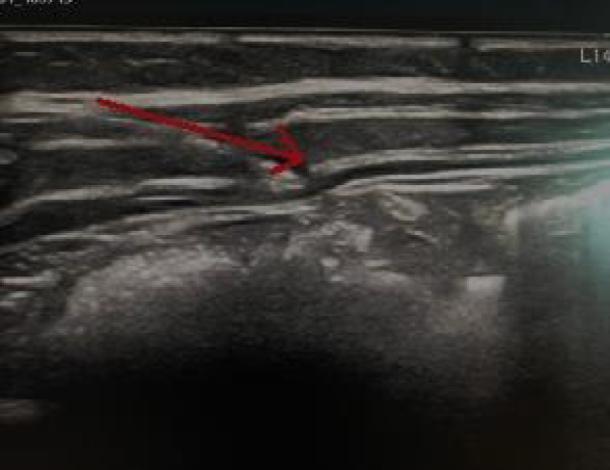
Diagnostic ultrasound image illustrating a Transversus Abdominis Plane (TAP) block procedure. The image displays the anatomical stratification of the abdominal wall, showing distinct horizontal layers including the external oblique, internal oblique, and transversus abdominis muscles separated by hyperechoic fascial planes. A prominent red arrow indicates the targeted needle trajectory toward the neurofascial plane between the internal oblique and transversus abdominis muscles. A localized anechoic to hypoechoic area at the tip of the arrow suggests the initiation of local anesthetic deposition. This imaging demonstrates the real-time visual guidance used in regional anesthesia to ensure precise delivery of medication for postoperative analgesia. The deep aspect of the image shows intra-abdominal structures appearing more heterogeneous and hypoechoic beneath the transversalis fascia.
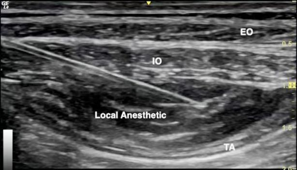
This diagnostic ultrasound image demonstrates a transversus abdominis plane (TAP) block procedure. The image depicts the layered anatomy of the lateral abdominal wall, showing three distinct muscle layers from superficial to deep: the external oblique (EO), internal oblique (IO), and transversus abdominis (TA) muscles. A hyperechoic, linear needle is visible entering from the left at an oblique angle, with its tip precisely positioned in the fascial plane between the IO and TA muscles. An anechoic to hypoechoic area is labeled 'Local Anesthetic,' showing the characteristic hydrodissection and separation of the IO and TA muscle layers as the fluid expands the potential space. This visual serves as a primary educational tool for regional anesthesia, illustrating real-time needle guidance and successful fascial plane infiltration for postoperative pain management. The image includes depth markers on the right and standard anatomical labels, making it suitable for training in ultrasound-guided nerve blocks.
This diagnostic ultrasound image demonstrates a Transversus Abdominis Plane (TAP) block, a regional anesthesia technique. The image displays the distinct anatomical layers of the anterolateral abdominal wall. Labeled structures include the External Oblique (EO) as the most superficial muscle layer, followed by the Internal Oblique (IO) muscle. The deepest visualized layer is the Transversus Abdominis (TA) muscle. The muscle layers appear as relatively hyperechoic bands with a striated texture. A prominent hypoechoic (dark) fluid collection is visible between the IO and TA muscles, representing the correctly placed local anesthetic within the transversus abdominis plane. This clinical image is used to teach ultrasound-guided needle placement and the recognition of fascial planes for postoperative analgesia in abdominal surgery, such as laparoscopic rectal cancer resection. The visualization confirms the target plane for drug deposition to achieve sensory blockade of the anterior abdominal wall nerves.
quadratus lumborum block ultrasound anatomy QL muscle posterior abdominal wall
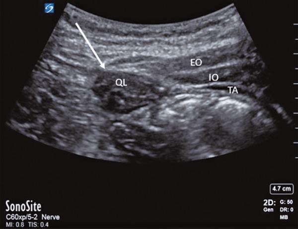
This diagnostic ultrasound image demonstrates the sonographic anatomy of the posterior abdominal wall, specifically configured for a Quadratus Lumborum Block (QLB). The image shows four distinct muscle layers identified with labels: the External Oblique (EO), Internal Oblique (IO), and Transversus Abdominis (TA) muscles are visible as superficial, relatively hypoechoic parallel bands. Deep to these layers and located more posteriorly is the Quadratus Lumborum muscle (QL), which exhibits a more heterogeneous echotexture compared to the superficial abdominal wall muscles. A white arrow specifically indicates the posterior border of the QL muscle, which serves as a critical landmark for the deposition of local anesthetic in a posterior QL block approach. This clinical imaging is essential for regional anesthesia training, illustrating the spatial relationship between the anterolateral abdominal wall muscles and the posterior lumbar musculature to ensure safe needle placement and effective analgesic distribution.
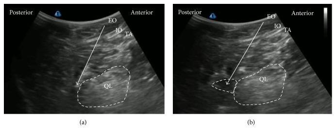
This diagnostic ultrasound comparison illustrates a posterior Quadratus Lumborum Block (QLB). Image (a) represents the pre-injection state, identifying the layered anatomy of the abdominal wall from anterior to posterior: the External Oblique (EO), Internal Oblique (IO), and Transversus Abdominis (TA) muscles. The Quadratus Lumborum (QL) muscle is outlined in the deeper plane. A white arrow indicates the needle trajectory approaching the posterior aspect of the QL. Image (b) shows the post-injection state, where the spread of local anesthetic is visualized as an anechoic (dark) fluid collection, demarcated by a white dotted line, adjacent to the QL muscle and within the lumbar interfascial triangle (LIFT). The image serves as a clinical guide for regional anesthesia, demonstrating the correct needle placement and subsequent anesthetic distribution required for effective pain management in the lumbar and abdominal regions. The orientation is labeled with posterior and anterior landmarks to aid in cross-sectional anatomical correlation.
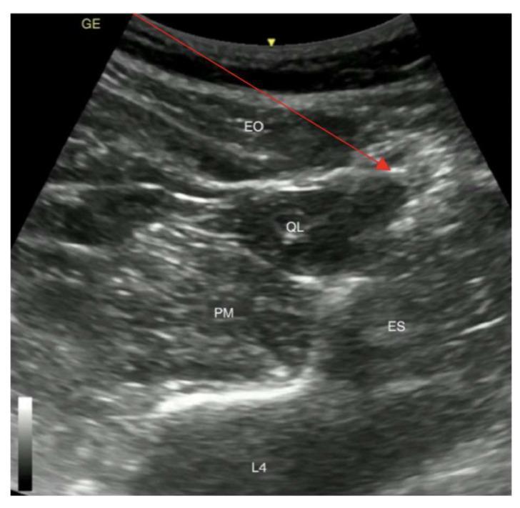
This diagnostic ultrasound image demonstrates the regional anatomy for a posterior Quadratus Lumborum Block (QLB type 2). The sonogram shows a transverse view of the abdominal wall and paraspinal musculature at the level of the fourth lumbar vertebra (L4). Key anatomical structures are labeled, including the superficial external oblique (EO) muscle, the quadratus lumborum (QL) muscle, the psoas major (PM) muscle situated anteriorly, and the erector spinae (ES) muscle group located posteriorly. The hyperechoic shadow of the L4 vertebral body serves as a deep posterior landmark. A yellow arrow identifies the patient's skin surface. A red arrow illustrates the planned needle trajectory for a posterior QLB, originating from the skin, traversing the EO, and targeting the interfacial plane on the posterior aspect of the QL muscle (the 'shamrock sign' area). This image is an essential educational resource for regional anesthesia, illustrating the sonographic landmarks required for safe and effective truncal nerve blocks.
"transversus abdominis plane block" AND postoperative analgesia
"quadratus lumborum block" AND analgesia
BLOCK 1: TRANSVERSUS ABDOMINIS PLANE (TAP) BLOCK
1. DEFINITION
- A fascial plane block in which local anaesthetic is deposited in the neurovascular plane between the internal oblique (IO) and transversus abdominis (TA) muscles of the anterolateral abdominal wall
- Produces somatic anaesthesia/analgesia of the anterior abdominal wall
- First described by Rafi (2001) using a landmark technique; later refined with ultrasound guidance by McDonnell et al. (2007) and Hebbard et al. (2010)
Exam Tip: TAP block is a somatic-only block — it has NO visceral analgesia. This is its most important limitation and a favourite viva point.
2. RELEVANT ANATOMY
2.1 Abdominal Wall Layers (Medial to Lateral — Mnemonic: "Skin-SEITA-Peri")
ANTERIOR ABDOMINAL WALL LAYERS (superficial → deep):
────────────────────────────────────────────────
1. Skin
2. Subcutaneous fat (Camper's fascia superficial, Scarpa's fascia deep)
3. EXTERNAL OBLIQUE MUSCLE (EO)
4. INTERNAL OBLIQUE MUSCLE (IO)
5. [TAP PLANE] ← TARGET injection zone
6. TRANSVERSUS ABDOMINIS MUSCLE (TA)
7. Transversalis fascia
8. Extraperitoneal fat
9. PERITONEUM
────────────────────────────────────────────────
2.2 Nerves in the TAP Plane
| Nerve | Root | Coverage |
|---|---|---|
| Intercostal nerves T7–T11 | T7–T11 | Upper and central abdomen |
| Subcostal nerve | T12 | Below umbilicus, inguinal region |
| Iliohypogastric nerve | L1 | Inguinal/suprapubic |
| Ilioinguinal nerve | L1 | Inguinal, scrotum/labia |
| Lateral femoral cutaneous nerve | L2, L3 | (variable, not reliably blocked) |
- These nerves run laterally to medially within the TAP plane
- They supply the skin, muscle, and parietal peritoneum of the anterior abdominal wall — but NOT visceral peritoneum or intra-abdominal organs
2.3 Triangle of Petit (Lumbar Triangle) — Landmark Approach
TRIANGLE OF PETIT (Petit's triangle):
─────────────────────────────
Posterior: LATISSIMUS DORSI (posterior border)
Anterior:  EXTERNAL OBLIQUE (anterior border)
Inferior:  ILIAC CREST (floor)
─────────────────────────────
Floor: INTERNAL OBLIQUE MUSCLE
- The Triangle of Petit was the original landmark for blind TAP block (finger-guided double-pop technique)
- Largely replaced by US guidance
Viva Pearl: The Triangle of Petit (lumbar triangle) is the anatomical basis for the original landmark TAP block. It is bounded by latissimus dorsi (posterior), external oblique (anterior), and iliac crest (inferior). The floor is the internal oblique — needle enters here, crosses IO, enters TAP plane with a "double-pop."
3. APPROACHES TO TAP BLOCK
TAP BLOCK APPROACHES
        |
   _____|______________________________________
   |          |          |          |          |
LATERAL   SUBCOSTAL  POSTERIOR ILIOINGUINAL  OBLIQUE
(midax.)  (upper     (PLT     (Hebbard's    SUBCOSTAL
           abdomen)   approach) modified)
Classification Table
| Approach | Probe Position | Coverage | Best For |
|---|---|---|---|
| Lateral / Midaxillary TAP | Between ASIS and costal margin, midaxillary line | T10–L1 (below umbilicus, lateral wall) | Lower abdominal surgery (below umbilicus) |
| Subcostal TAP | Parallel to costal margin (subcostally) | T6–T10 (upper abdomen) | Upper abdominal surgery (above umbilicus), laparoscopic cholecystectomy |
| Posterior TAP (PLT) | Posterior to midaxillary line, near QL | T10–L1 (broader coverage, some visceral) | More extensive coverage; approaches QL territory |
| Oblique Subcostal TAP | From xiphoid laterally to ASIS (oblique) | T6–L1 (full anterior wall) | Full abdominal wall coverage |
| Continuous TAP (catheter) | Any approach with catheter insertion | Prolonged coverage | ERAS, major abdominal surgery |
4. SURGICAL AND CLINICAL INDICATIONS
4.1 By Surgery Type
| Surgery | Recommended Approach |
|---|---|
| Laparoscopic cholecystectomy | Bilateral subcostal TAP |
| Appendicectomy | Right lateral TAP |
| Caesarean section | Bilateral lateral + subcostal TAP |
| Total abdominal hysterectomy | Bilateral lateral TAP |
| Inguinal hernia repair | Unilateral lateral TAP (or ilioinguinal/iliohypogastric block) |
| Colostomy/ileostomy | Ipsilateral lateral TAP |
| Laparoscopic nephrectomy | Ipsilateral posterior TAP |
| Open abdominal surgery (ERAS) | Bilateral oblique subcostal TAP |
| Abdominal wall hernia repair | Bilateral TAP |
| Prostatectomy (laparoscopic) | Bilateral lateral TAP |
4.2 ERAS Applications
- TAP block is a cornerstone of ERAS (Enhanced Recovery After Surgery) protocols for abdominal surgery
- Part of multimodal opioid-sparing analgesia
- Most effective when combined with regular paracetamol, NSAIDs, and dexamethasone
5. ULTRASOUND-GUIDED TECHNIQUE
Patient Position
- Supine (routine); lateral decubitus (posterior approach)
Equipment
- Probe: High-frequency linear (13–6 MHz); curvilinear for obese patients
- Needle: 22G, 80–100mm, echogenic, short-bevel
Step-by-Step Technique (Lateral/Midaxillary TAP)
STEP 1: Patient supine; probe between iliac crest and costal margin,
         MIDAXILLARY line, TRANSVERSE orientation

STEP 2: Identify 3 layers = "THREE-LAYER-CAKE SIGN":
         EO (most superficial)
         IO (middle)
         TA (deepest)
         Between IO and TA = bright fascial line = TARGET

STEP 3: Apply colour Doppler — identify circumflex iliac vessels
         (within TAP plane, must avoid)

STEP 4: Insert 22G needle IN-PLANE from ANTERIOR to POSTERIOR
         (medial to lateral or lateral to medial)

STEP 5: Advance needle tip to fascial plane between IO and TA

STEP 6: Hydrodissection: inject 1–2 mL saline → confirm plane opening
         (IO lifts off TA)

STEP 7: Aspiration × 2 planes

STEP 8: Inject 20–30 mL LA in incremental boluses (5 mL aliquots)

STEP 9: Watch for "KAYAK SIGN" — elliptical separation of IO from TA
         = correct plane = successful injection

STEP 10: Repeat on contralateral side for bilateral TAP
The "KAYAK SIGN" — Key Sonographic Endpoint
- When LA is correctly injected into the TAP plane, the fascial planes of IO and TA separate, creating a lens-shaped/kayak-shaped hypoechoic fluid space — this is the Kayak sign
- If LA is seen entering the muscle (hyperechoic intramuscular spread) — incorrect plane
Exam Tip: The "Kayak sign" = correct TAP injection. The three-layer "cake" on US = EO, IO, TA. These are favourite viva observations.
Subcostal TAP Technique
- Probe: Parallel and 2 cm below the costal margin
- Target: Same TAP plane (between IO and TA) but at the subcostal level (T6–T10)
- Needle: In-plane, lateral to medial along the costal margin
- Used for upper abdominal surgery (cholecystectomy, gastrectomy)
6. DRUG DOSES
| Drug | Concentration | Volume per side | Bilateral total | Duration |
|---|---|---|---|---|
| Ropivacaine | 0.375–0.5% | 15–20 mL | 30–40 mL | 8–16 h |
| Bupivacaine | 0.25% | 15–20 mL | 30–40 mL | 10–18 h |
| Levobupivacaine | 0.25–0.375% | 15–20 mL | 30–40 mL | 10–18 h |
| Liposomal bupivacaine | 1.3% | 20 mL/side | 40 mL | 72 h |
- Maximum volumes: Bilateral TAP must not exceed 3 mg/kg ropivacaine total
- Dexamethasone 4–8 mg as adjuvant extends duration by 6–8 hours
- Intraoperative surgeon-performed TAP: ropivacaine 0.375% (diluted) is preferred
7. ASSESSMENT OF BLOCK
| Test | Finding |
|---|---|
| Pin-prick T10–L1 | Loss of sharp sensation — T10 at umbilicus, L1 inguinal |
| Motor | No motor block (purely sensory fascial plane block) |
| Onset | 15–30 minutes |
| Failure | No sensory change at 30 min = missed plane |
8. AREAS ANAESTHETISED
| Approach | Dermatomes Covered | Structures |
|---|---|---|
| Lateral TAP | T10–L1 | Infraumbilical anterior wall, inguinal region |
| Subcostal TAP | T6–T10 | Supraumbilical wall, epigastrium |
| Oblique subcostal TAP | T6–L1 | Full anterior abdominal wall (bilateral) |
| NOT covered | Visceral peritoneum, pelvic viscera | No visceral analgesia |
| NOT covered | Posterior abdominal wall, midline | Incomplete for midline incisions |
9. ADVANTAGES AND DISADVANTAGES
| Advantages | Disadvantages |
|---|---|
| Simple, safe, reproducible | Somatic only — NO visceral analgesia |
| No haemodynamic effects | Large volume required (LAST risk) |
| No motor block | Limited midline coverage |
| Can be performed under GA | Must be bilateral for midline incisions |
| Excellent for ERAS | Inferior to epidural for major surgery |
| Surgeon can perform at end of surgery | Short duration (single-shot) |
| Avoids neuraxial risks | Variable spread |
| Safe in anticoagulated patients | No coverage above umbilicus (lateral approach) |
10. COMPLICATIONS
| Complication | Mechanism | Prevention | Management |
|---|---|---|---|
| LAST | High volume bilateral; vascular in TAP plane | Aspiration, incremental injection, US | Intralipid 20% protocol |
| Peritoneal puncture | Needle too deep (TA is thin) | Real-time US guidance; TA very thin — stop when fascial plane reached | Observe; surgical review if haematoma |
| Bowel injury | Deep injection past TA | US with peritoneum visualised | Surgical review |
| Femoral nerve palsy | LA spread anteriorly via lumbar fascia | Posterior approach caution | Physiotherapy; resolves |
| Haematoma | Circumflex iliac vessel injury | Colour Doppler before injection | Observation; compression |
| Block failure | Wrong fascial plane (intramuscular injection) | Confirm "Kayak sign" | Repeat with correct technique |
11. RECENT EVIDENCE (2024–2026)
| Study | Finding |
|---|---|
| Zako et al. BJA 2026 [PMID: 41339171] | TAP block RCT systematic review and meta-analysis: significant reduction in opioid consumption (24h morphine equivalent: −10 mg) and pain scores at rest/movement; most effective for lower abdominal surgery |
| Bourgeois et al. PROSPECT, Eur J Anaesthesiol 2024 [PMID: 39129451] | For laparoscopic cholecystectomy: subcostal TAP or infiltration recommended as first-line alongside paracetamol/NSAIDs; epidural not recommended |
| Gao et al. Langenbecks 2023 [PMID: 37851271] | TAP vs QL block for inguinal hernia repair: QL block superior in opioid-sparing; TAP still effective and technically simpler |
| Liposomal bupivacaine TAP 2024 | 72-hour analgesia with Exparel in TAP for caesarean section — equivalent to epidural for somatic component |
BLOCK 2: QUADRATUS LUMBORUM BLOCK (QL BLOCK)
1. DEFINITION
- An ultrasound-guided interfascial plane block in which local anaesthetic is deposited around the quadratus lumborum (QL) muscle at the thoracolumbar fascia (TLF), producing somatic + visceral analgesia for the abdominal wall and lower thoracic regions
- First described by Blanco (2012) as an extension of the TAP block
- Distinct from TAP block by its posterior injection site, deeper fascial plane, and ability to provide some visceral analgesia via paravertebral spread through the thoracolumbar fascia
Viva Pearl — Critical Distinction: The key advantage of QL block over TAP block is that QL block provides BOTH somatic AND some visceral analgesia because LA spreads through the TLF into the paravertebral space, blocking sympathetic fibres. TAP block is somatic only.
2. ANATOMY OF THE QUADRATUS LUMBORUM MUSCLE
2.1 Muscle Details
| Feature | Detail |
|---|---|
| Origin | Posterior iliac crest and iliolumbar ligament |
| Insertion | Inferior border of 12th rib and transverse processes of L1–L4 |
| Function | Lateral flexion of trunk; fixes 12th rib during inspiration |
| Innervation | Anterior rami of T12, L1–L4 (subcostal and lumbar nerves) |
| Relations | Anterior: psoas major; Posterior: erector spinae; Medial: lumbar transverse processes, aorta/IVC; Superior: 12th rib; Lateral: transversus abdominis |
2.2 Thoracolumbar Fascia (TLF) — Key to QL Block Mechanism
THORACOLUMBAR FASCIA (TLF) — 3 Layers:
────────────────────────────────────────
POSTERIOR LAYER: Covers erector spinae + QL posteriorly
                 → attachment of latissimus dorsi
MIDDLE LAYER:   Between QL and erector spinae
ANTERIOR LAYER: Between QL and psoas major
                → continuous with fascia transversalis
────────────────────────────────────────
The TLF contains:
• Mechanoreceptors + nociceptors → pain modulation
• Sympathetic fibres (via lumbar sympathetic chain)
• Connects to PARAVERTEBRAL SPACE (via intertransverse membrane)
→ LA spread to PVS = visceral analgesia mechanism
2.3 "SHAMROCK SIGN" — Key US Landmark
ULTRASOUND "SHAMROCK SIGN" (transverse view at L4):
         [TRANSVERSE PROCESS] ← "stem of shamrock"
                |
      __________|__________
      |                   |
 ERECTOR               PSOAS
 SPINAE                MAJOR
 (posterior leaf)      (anterior leaf)
      |
  QUADRATUS
  LUMBORUM
  (lateral leaf)
─────────────────────────────────────────────────────
Mnemonic: PQRST at midaxillary cross-section:
P = Psoas (anterior)
Q = Quadratus lumborum (central)
R = (target: posterior/lateral/anterior aspects of QL)
S = Spine / transverse process (posterior)
T = Transversus abdominis aponeurosis (anterior-lateral)
3. CLASSIFICATION OF QL BLOCK TYPES
QL BLOCK TYPES (by injection site relative to QL muscle):
                    QL MUSCLE
                    ┌──────┐
         QL1 (Lat.) │      │ QL3 (Ant./Transmuscular)
      ←─────────────┤  QL  ├─────────────────→
                    │      │
                    └──────┘
                        │
                   QL2 (Post.)
                        ↓
Detailed Comparison of QL Block Types
| Feature | QL1 (Lateral) | QL2 (Posterior) | QL3 (Anterior/Transmuscular) |
|---|---|---|---|
| Injection site | Lateral border of QL (between TA aponeurosis and QL) | Posterior to QL (between QL and erector spinae — central TLF) | Anterior to QL (between QL and psoas major) |
| Fascia targeted | Lateral TLF | Posterior + middle TLF | Anterior TLF |
| Coverage | T10–L1 | T4–L1 (broader) | T4–L1 + lumbar plexus (best visceral coverage) |
| Visceral component | Minimal | Moderate | Best (via paravertebral spread) |
| Depth | Superficial | Moderate | Deepest |
| Kidney risk | Low | Moderate | Highest |
| Ease | Easiest | Intermediate | Most difficult |
| First described | Blanco 2012 | Blanco 2012 | Børglum 2013 |
| Best for | Lower abdominal (infraumbilical) | Thoracoabdominal surgery | Hip, pelvic, caesarean section |
Exam Tip: QL3 (transmuscular) provides the most extensive coverage including partial lumbar plexus block — but carries highest risk of kidney puncture and requires deepest needle pass. Always use US guidance with real-time Doppler.
4. SURGICAL AND CLINICAL INDICATIONS
| Surgery/Indication | Recommended QL Type |
|---|---|
| Caesarean section | Bilateral QL3 or QL2 |
| Hip arthroplasty | QL3 (L1–L3 coverage, partial lumbar plexus) |
| Inguinal hernia repair | QL1 or QL2 |
| Laparoscopic appendicectomy | Right QL1/QL2 |
| Colostomy/ileostomy | Ipsilateral QL |
| Nephrectomy (open/laparoscopic) | Ipsilateral QL3 |
| Abdominal hysterectomy | Bilateral QL |
| ERAS — abdominal surgery | Bilateral QL (superior to TAP) |
| Hip fracture | QL3 (adjunct to PENG block) |
| Paediatric abdominal surgery | QL1 (0.5 mL/kg ropivacaine 0.2%) |
5. ULTRASOUND-GUIDED TECHNIQUE
Patient Position
- Lateral decubitus (preferred — gravity assists anatomy display)
- Supine with probe posterior (feasible)
- Prone (for posterior approach)
Probe
- Linear (13–6 MHz) for adults and older children
- Curvilinear (5–1 MHz) for obese patients or QL3
Scanning Protocol — Shamrock View
STEP 1: Start probe at MID-AXILLARY LINE between iliac crest
         and costal margin (like TAP block)
STEP 2: Identify EO, IO, TA muscle layers
STEP 3: SLIDE probe POSTERIORLY until TA muscle transitions
         to TA APONEUROSIS (bright fascial sheet)
STEP 4: Continue sliding posteriorly → QL muscle appears
         as the SHAMROCK SIGN
         - QL = posterior leaf
         - Psoas = anterior leaf
         - Erector spinae = posterior-medial leaf
         - Transverse process = stem
STEP 5: Identify target plane based on approach type:
         QL1: Lateral to QL (between TA aponeurosis and QL)
         QL2: Posterior to QL (between QL and erector spinae)
         QL3: Anterior to QL (between QL and psoas)
STEP 6: Colour Doppler — identify lumbar vessels, kidney
STEP 7: Insert needle in-plane (posterior to anterior for QL1/QL2;
         lateral to medial for QL3)
STEP 8: Aspirate, inject 1 mL saline for hydrodissection,
         confirm plane, then inject LA
Sonoanatomy Layers (from posterior, lateral decubitus)
[Skin]
[Latissimus dorsi]
[Erector spinae muscles]
─── QL2 injection plane (between QL and ES) ───
[QUADRATUS LUMBORUM MUSCLE]
─── QL1 injection plane (between TA aponeurosis and QL) ───
[TA APONEUROSIS / transversalis fascia]
─── QL3 injection plane (between QL and psoas) ───
[PSOAS MAJOR MUSCLE]
[Lumbar plexus nerves within psoas]
[KIDNEY] ← Danger — especially with QL3
[Transverse process of L4] ← hyperechoic with shadow
6. DRUG DOSES
| Drug | Concentration | Volume per side | Paediatric |
|---|---|---|---|
| Ropivacaine | 0.2–0.375% | 20–30 mL | 0.5 mL/kg (max 3 mg/kg, < 20 mL/side) |
| Bupivacaine | 0.125–0.25% | 20–25 mL | 0.5 mL/kg (max 2.5 mg/kg) |
| Levobupivacaine | 0.125–0.25% | 20–25 mL | — |
| Continuous catheter | Ropivacaine 0.2% | 5–10 mL/h | — |
- Bilateral QL block total: Must not exceed 3 mg/kg ropivacaine
- Needle: 50–100mm, 22G, short-bevel, echogenic
7. MECHANISM OF QL BLOCK — WHY BETTER THAN TAP
QL BLOCK MECHANISM:
LA deposited at TLF around QL muscle
        ↓
Spreads along TLF (posterior/middle/anterior layers)
        ↓
Permeates through intertransverse ligament
        ↓
Reaches PARAVERTEBRAL SPACE (T8–L4)
        ↓
Blocks: DORSAL RAMI + VENTRAL RAMI + SYMPATHETIC CHAIN
        ↓
Result: SOMATIC + VISCERAL + SYMPATHETIC ANALGESIA
(Superior to TAP which is somatic-only)
Viva Pearl: QL block covers dermatomal levels T8–L1 (QL2) or T4–L1 (QL3), whereas lateral TAP block covers only T10–L1. QL3 is the only abdominal wall block that reliably provides some visceral analgesia because of paravertebral spread through the TLF.
8. COMPLICATIONS
| Complication | Mechanism | Incidence | Prevention | Management |
|---|---|---|---|---|
| Kidney puncture | Needle too anterior (QL3) | Rare with US | Real-time US + Doppler; identify kidney before QL3 | Observation; urology consult if haematuria |
| LAST | High bilateral volumes; lumbar vascularity | Low | Aspiration; incremental injection | Intralipid 20% |
| Lumbar plexus injection | Needle too deep (QL3) | Rare | Confirm plane with hydrodissection | Observe; physiotherapy for weakness |
| Peritoneal/bowel injury | Anteriorly displaced needle | Rare | US guidance; visualise TA aponeurosis | Surgical review |
| Block failure | Wrong fascial plane | 10–20% | Confirm shamrock sign; visualise LA spread | Repeat block or supplementary analgesia |
| Haematoma | Lumbar vessel injury | Rare | Doppler screening | Conservative/surgical |
| Epidural/intrathecal spread | QL3 → paravertebral → epidural | Very rare | Do not inject against resistance | Resuscitation |
9. QL BLOCK vs. TAP BLOCK — COMPARISON TABLE
| Feature | TAP Block | QL Block (QL2/QL3) |
|---|---|---|
| Plane | IO–TA fascial plane | TLF around QL muscle |
| Location | Midaxillary/subcostal | Posterior to TA aponeurosis |
| Nerves | T7–L1 lateral cutaneous branches | T4–L1 (dorsal + ventral rami via PVS) |
| Visceral analgesia | No | Yes (QL2/QL3) |
| Sympathetic block | No | Yes (via PVS spread) |
| Depth from skin | 2–4 cm | 4–8 cm |
| Volume | 15–20 mL/side | 20–30 mL/side |
| Coverage (unilateral) | T10–L1 (lateral) or T6–T10 (subcostal) | T4/T8–L1 |
| Best for | Infraumbilical surgery, day-case | Caesarean section, hip, renal surgery |
| Kidney risk | None | Present (QL3) |
| Ease of performance | Easier | More complex |
| Evidence (inguinal hernia) | Good | Superior — Gao et al. 2023 |
| Duration | 8–16 h | 12–24 h (deeper spread) |
| ERAS suitability | Excellent | Excellent + superior for visceral surgery |
10. COMPARISON WITH OTHER ABDOMINAL WALL BLOCKS
| Block | Coverage | Visceral | Volume | Best For |
|---|---|---|---|---|
| TAP (lateral) | T10–L1 | No | 15–20 mL | Infraumbilical |
| TAP (subcostal) | T6–T10 | No | 15–20 mL | Cholecystectomy |
| QL1 | T10–L1 | Minimal | 20–30 mL | Lower abdominal |
| QL2 | T4–L1 | Moderate | 20–30 mL | Thoracoabdominal |
| QL3 | T4–L1 + lumbar plexus | Best | 20–30 mL | Caesarean, hip |
| ESP (lumbar) | T6–L3 | Moderate | 20–30 mL | Posterior abdominal |
| Rectus sheath | T7–T12 midline | No | 10–20 mL | Midline incisions |
| QLBP (lumbar plexus) | L1–L4 | Partial | 30–40 mL | Hip/thigh surgery |
11. RECENT EVIDENCE (2024–2026)
| Study | Finding |
|---|---|
| Gao et al. Langenbecks 2023 [PMID: 37851271] | QL block superior to TAP for inguinal hernia repair — lower VAS, less opioid at 24h; QL recommended preferentially |
| Zako et al. BJA 2026 [PMID: 41339171] | TAP block systematic review — effective opioid-sparing (−10 mg morphine equivalent/24h); most evidence in lower abdominal and caesarean surgery |
| Bourgeois PROSPECT 2024 [PMID: 39129451] | Subcostal TAP recommended for laparoscopic cholecystectomy alongside multimodal analgesia |
| Lee et al. BJA 2025 [PMID: 40483183] | Network meta-analysis for total hip arthroplasty: QL3 block ranked highly effective for post-THA analgesia alongside spinal anaesthesia |
| QL for caesarean section 2024–2025 | Multiple RCTs show QL3 reduces opioid consumption ≥ 50% after spinal anaesthesia for CS; emerging as preferred block for CS in ERAS |
12. CURRENT GUIDELINES
| Organisation | Recommendation |
|---|---|
| ASRA 2022 | TAP and QL blocks recommended as components of multimodal analgesia; US guidance standard |
| ESRA 2023 | QL blocks preferred over TAP for surgeries with visceral component; bilateral QL for caesarean section ERAS |
| PROSPECT 2024 | Subcostal TAP first-line for laparoscopic cholecystectomy; TAP/QL for lower abdominal surgery |
| ESAIC 2024 | Fascial plane blocks (TAP/QL/ESP) endorsed in ERAS; injection pressure monitoring recommended |
13. CLINICAL PEARLS
- TAP is somatic-only — never expect visceral analgesia (e.g., uterine pain after CS, peritoneal irritation) from TAP alone
- "Kayak sign" = correct TAP plane — elliptical separation between IO and TA on US
- Subcostal TAP for upper abdominal surgery; lateral TAP for lower; oblique subcostal for whole anterior wall
- The transversus abdominis muscle is very thin (2–5 mm) — easy to penetrate into peritoneum; real-time US is essential
- QL block = TAP block evolved — same approach but slide probe more posteriorly to the shamrock sign
- "Shamrock sign" = key landmark for QL — QL (lateral leaf), psoas (anterior leaf), erector spinae (posterior leaf), transverse process (stem)
- For caesarean section, bilateral QL3 is the single most effective block — reduces opioid consumption by > 50% compared with spinal morphine alone
- QL3 carries kidney risk — always identify the kidney on US before needle insertion for QL3
- Circumflex iliac vessels run within the TAP plane at the ASIS level — always use Doppler before TAP injection
- For bilateral blocks, total ropivacaine must not exceed 3 mg/kg — LAST is real with bilateral 20–30 mL injections
- Intraoperative surgeon TAP (at laparotomy closure or laparoscopy) is as effective as anaesthetist-placed TAP — widely used in ERAS
- QL catheter provides prolonged analgesia (24–48h) — preferred over single-shot for major abdominal surgery
- Liposomal bupivacaine in TAP provides 72-hour analgesia — emerging practice for same-day discharge surgery
- QL2 (posterior QL) is the most commonly performed type — good coverage, lower kidney risk than QL3, easily identifiable plane
14. COMMON VIVA QUESTIONS
- T10–L1: lateral cutaneous branches of T10, T11, T12 (subcostal), L1 (ilioinguinal and iliohypogastric); NOT visceral peritoneum
- The TAP plane (between IO and TA) only carries somatic afferents of the abdominal wall; visceral pain travels via splanchnic nerves → coeliac plexus → sympathetic chain → NOT intercepted by TAP block
- When LA is correctly injected into the TAP plane, the IO and TA layers separate into an elliptical (kayak-shaped) hypoechoic fluid space. It confirms successful TAP plane injection.
- QL block is placed posteriorly at the thoracolumbar fascia around the QL muscle; LA spreads to the paravertebral space providing visceral + sympathetic analgesia; broader coverage (T4/T8–L1) vs. TAP (T10–L1); QL is superior in evidence for opioid-sparing
- The sonographic appearance on transverse US at L4: psoas major (anterior leaf), QL (lateral leaf), erector spinae (posterior leaf), and transverse process (stem) — resembling a 3-leaf shamrock. The transverse process is the "stem." Critical landmark for QL block.
- QL3 (transmuscular/anterior) — LA deposited anterior to QL muscle between QL and psoas; spreads directly into paravertebral space; partial lumbar plexus block; best for caesarean section and hip surgery
- P = Psoas major; Q = Quadratus lumborum; R = (target for injection); S = Spine/transverse process; T = Transversus abdominis aponeurosis. Used to remember structures seen on US from anterior to posterior
- Kidney puncture — the kidney lies anteriorly adjacent to the QL muscle at L1–L2. Always identify kidney on US before needle insertion for QL3.
- Gao et al. 2023 (Langenbecks): QL block superior to TAP for inguinal hernia repair — lower VAS scores and reduced opioid requirements at 24h. QL preferred when available.
- 0.5 mL/kg of 0.2% ropivacaine per side, maximum 3 mg/kg, not exceeding 20 mL per side
15. RAPID REVISION BOX
TAP BLOCK + QL BLOCK — ONE PAGE REVISION
━━━━━━━━━━━━━━━━━━━━━━━━━━━━━━━━━━━━━━━━━━━━━━━━━━
TAP BLOCK:
  Plane: Between IO and TA muscles (anterolateral wall)
  Nerves: T7–L1 lateral cutaneous (somatic ONLY)
  US sign: THREE-LAYER CAKE (EO–IO–TA) → KAYAK SIGN
  Probe: Transverse, midaxillary, between ASIS + costal margin
  Volume: 15–20 mL/side | Ropivacaine 0.375%
  KEY LIMITATION: NO VISCERAL ANALGESIA
  SUBCOSTAL TAP: T6–T10 | upper abdomen | cholecystectomy
  LATERAL TAP: T10–L1 | lower abdomen | CS, hernia
  Triangle of Petit: original landmark (LD + EO + iliac crest)
  Described: Rafi 2001 (landmark); McDonnell 2007 (US)

━━━━━━━━━━━━━━━━━━━━━━━━━━━━━━━━━━━━━━━━━━━━━━━━━━
QL BLOCK:
  Plane: TLF around quadratus lumborum
  Nerves: T4/T8–L1 via PVS spread → SOMATIC + VISCERAL
  US landmark: SHAMROCK SIGN (psoas/QL/erector spinae/TP)
  Mnemonic PQRST: P=Psoas Q=QL R=target S=Spine T=TA aponeurosis

  TYPES:
    QL1 (Lateral): Between TA aponeurosis and QL | T10–L1 | easiest
    QL2 (Posterior): Between QL and erector spinae | T4–L1 | moderate
    QL3 (Anterior/Transmuscular): Between QL and psoas | T4–L1
             + lumbar plexus | KIDNEY RISK | best visceral analgesia

  Volume: 20–30 mL/side | Ropivacaine 0.2–0.375%
  Paediatric: 0.5 mL/kg (max 3 mg/kg, ≤ 20 mL/side)
  Best for: Caesarean section, hip arthroplasty, renal surgery

━━━━━━━━━━━━━━━━━━━━━━━━━━━━━━━━━━━━━━━━━━━━━━━━━━
TAP vs QL:
  TAP: Simple | Somatic only | T10–L1 | 15–20 mL
  QL:  Complex | Somatic + Visceral | T4–L1 | 20–30 mL
  Evidence: QL > TAP for inguinal hernia (Gao 2023)
            QL3 > TAP for CS and hip (Lee BJA 2025)

BOTH BLOCKS:
  LAST RISK: Bilateral → total ≤ 3 mg/kg ropivacaine
  COMPLICATIONS: LAST | Peritoneal puncture | Haematoma
  QL3 ADDITIONAL: Kidney puncture — always identify kidney on US
  ERAS ROLE: Both are cornerstones of opioid-sparing ERAS
  2026 Evidence: Zako et al. BJA 2026 — TAP reduces morphine
                 −10 mg/24h; significant evidence base
━━━━━━━━━━━━━━━━━━━━━━━━━━━━━━━━━━━━━━━━━━━━━━━━━━
📋 UPDATED QUESTION TRACKER
✅ DISCUSSED (8 topics)
| # | Topic | Paper Reference |
|---|---|---|
| 1 | Brachial Plexus — anatomy, all routes, complications | Sec 15 P1/Q5 |
| 2 | Erector Spinae Plane Block | Sec 15 P4/Q4 |
| 3 | Serratus Anterior Plane Block | Sec 15 P4 |
| 4 | Paravertebral Block + Space | Sec 11 P2/Q12 |
| 5 | Coeliac Plexus — anatomy, block, indications, complications | Sec 15 P1/Q1; P2/Q6 |
| 6 | Stellate Ganglion Block | Sec 15 P1/Q8; P2/Q7 |
| 7 | TAP Block | Sec 15 P1/Q2; P4/Q2 |
| 8 | Quadratus Lumborum Block | Sec 15 P1/Q7; P2/Q10 |
Femoral nerve block, adductor canal block, peng block, obturator nerve block
femoral nerve block ultrasound femoral triangle femoral artery nerve fascia iliaca
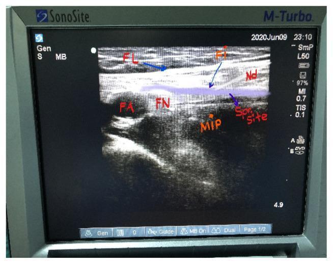
This diagnostic ultrasound image demonstrates a Ultrasound-Guided Fascia Iliaca Compartment Block (FICB) in the inguinal region. The primary anatomical landmarks are labeled: the Fascia Lata (FL) and Fascia Iliaca (FI) appear as distinct, parallel hyperechoic (bright) linear structures. Deep to these layers, the Femoral Artery (FA) and Femoral Nerve (FN) are visible, along with the hypoechoic Musculus Iliopsoas (MIP). A block needle (Nd) is visualized as a hyperechoic linear instrument advancing toward the potential space deep to the fascia iliaca. The 'Sp Site' (spread site) highlights a hypoechoic area representing the deposition and distribution of local anesthetic within the iliacus compartment, confirming successful needle placement. This image serves as an educational reference for regional anesthesia techniques, illustrating the anatomical planes and real-time visualization required for safe needle guidance and adequate anesthetic spread to target the femoral, obturator, and lateral femoral cutaneous nerves.
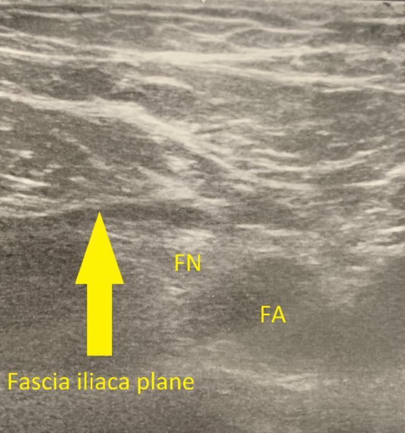
This diagnostic image is a gray-scale musculoskeletal ultrasound showing the regional anatomy of the inguinal area, specifically oriented for a fascia iliaca block (FIB). The visual demonstrates the fascia iliaca plane, marked by a prominent yellow arrow, which appears as a distinct hypoechoic linear interface separating the superficial muscle layers from deeper structures. Labeled in yellow text are the femoral nerve (FN) and femoral artery (FA), providing crucial landmarks for regional anesthesia. The femoral nerve is seen as a cluster of hyperechoic dots superior-medial to the pulsatile, anechoic femoral artery. The surrounding iliacus muscle exhibits a heterogeneous texture with characteristic hyperechoic septa. This image serves as a clinical guide for identifying the target injection site for a fascia iliaca compartment block, a procedure used for opioid-sparing analgesia in hip arthroplasty and femoral fractures. The visualization highlights the necessary precision for needle placement to ensure effective anesthetic spread across the femoral, lateral femoral cutaneous, and obturator nerves.
adductor canal block ultrasound saphenous nerve sartorius vastus medialis
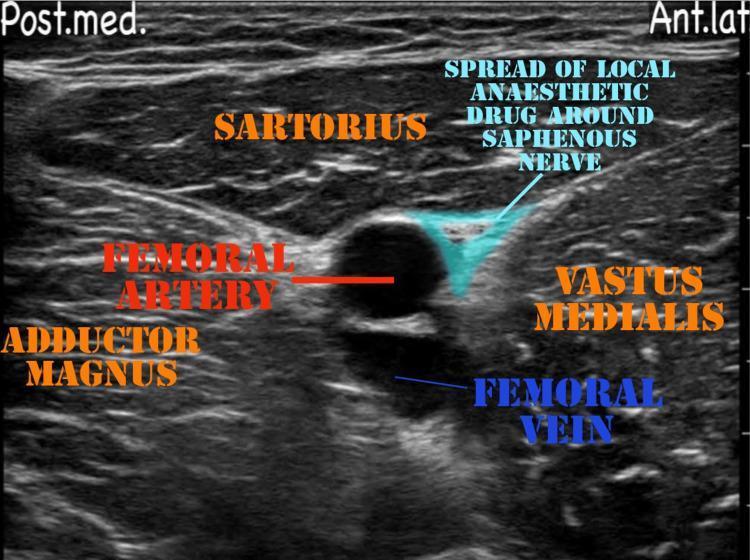
This diagnostic ultrasound image demonstrates the regional anatomy and needle-guided local anesthetic spread for an adductor canal block. The transverse view shows the sartorius muscle located superiorly (superficially) to the neurovascular bundle. Deep to the sartorius, the femoral artery appears as a prominent anechoic circular structure, with the femoral vein positioned deeper and slightly posterior. The vastus medialis muscle forms the lateral boundary, while the adductor magnus is visible in the posterior-medial aspect. A key clinical feature is the highlighted hypoechoic region representing the local anesthetic drug spread around the saphenous nerve, located in the subsartorial space (adductor canal) adjacent to the femoral artery and vastus medialis. Orientation markers indicate the posterior-medial ('Post.med.') and anterior-lateral ('Ant.lat.') axes. This visual serves as a pedagogical tool for anesthesiology and pain management, illustrating proper drug deposition to achieve sensory blockade of the medial thigh and knee while sparing motor function.
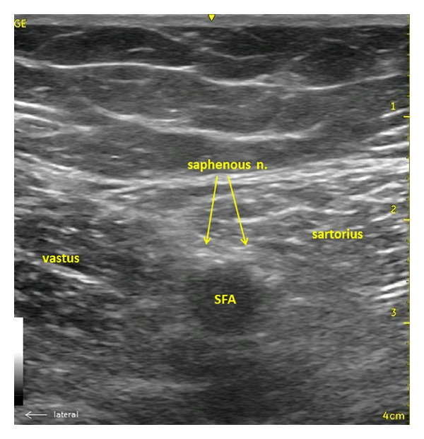
**Imaging Modality:** B-mode Ultrasound (Sonoanatomy) **Anatomical Region:** Mid-thigh, transverse cross-section at the level of the adductor canal. **Key Landmarks and Structures:** * **Musculature:** The sartorius muscle is visible medially/superficially, and the vastus medialis is situated laterally. * **Vasculature:** The superficial femoral artery (SFA) appears as a prominent, anechoic circular structure deep to the sartorius muscle. * **Neural Structures:** The saphenous nerve is identified as small, hyperechoic, honeycomb-patterned fascicles located anterolateral to the SFA, deep to the sartorius muscle, and superficial to the adductor canal. **Visual Features:** The image demonstrates the characteristic fascial planes separating the anterior and medial thigh compartments. The saphenous nerve is highlighted with yellow arrows, showcasing its position relative to the pulsatile artery and the overlying sartorius muscle. **Clinical Context:** This view is essential for ultrasound-guided regional anesthesia, specifically for performing an adductor canal block to provide sensory blockade of the saphenous nerve for distal knee and foot surgery.
PENG block pericapsular nerve group hip ultrasound anterior inferior iliac spine pubic ramus
A diagnostic ultrasound image demonstrating the sonographic anatomy required for a Pericapsular Nerve Group (PENG) block in the pelvic/hip region. The image shows the characteristic hyperechoic (bright) bony landmarks of the anterior inferior iliac spine (AIIS) and the iliopubic eminence (IPE), the latter appearing as a rounded structure with acoustic shadowing. Anatomical landmarks are labeled: the femoral artery (FA) appears as a hypoechoic (dark) circular vascular structure located superior and medial to the bony pelvis; the pectineus muscle (PE) is visible adjacent to the IPE. White arrows indicate the target fascial plane between the iliopsoas tendon and the pubic ramus for local anesthetic injection. Directional markers at the top right indicate anterior and medial orientations. This educational image illustrates the precise placement for regional anesthesia to provide analgesia for hip fractures or surgeries by targeting the articular branches of the femoral and obturator nerves.
This diagnostic ultrasound image demonstrates the anatomical landmarks and needle trajectory for a Pericapsular Nerve Group (PENG) block, a regional anesthesia technique for hip pain. The image, captured in a transverse plane using a curvilinear transducer, shows key hyperechoic (bright) bony structures: the Anterior Inferior Iliac Spine (AIIS) and the more medially located Ilio-Pubic Eminence (IPE). The Femoral Artery (FA) is visible as a hypoechoic (dark), circular pulsatile structure lateral to the IPE. A series of three black arrows indicate the in-plane needle trajectory, advancing from a lateral to medial direction. The echogenic needle tip is positioned in the fascial plane between the psoas tendon and the pubic ramus, adjacent to the IPE, which is the target site for local anesthetic deposition. This visualization is critical for clinicians to ensure accurate needle placement while avoiding neurovascular structures during regional nerve blocks in orthopedic surgery or emergency medicine.
"adductor canal block" AND "total knee arthroplasty"
"PENG block" AND hip fracture analgesia
"adductor canal block" AND knee arthroplasty quadriceps
LOWER LIMB BLOCKS — ENUMERATE AND DISCUSS
PART A: ENUMERATION OF LOWER LIMB BLOCKS
LOWER LIMB NERVE SUPPLY:
    LUMBAR PLEXUS (L1–L4)         SACRAL PLEXUS (L4–S3)
          |                                |
  ________|________              __________|__________
  |    |    |    |               |                   |
  FN  LFCN  ON   GFN          Sciatic nerve       Other
  |                             /        \
  |                          Common     Tibial
  Fem. n. → Saphenous n.     Peroneal
Complete Lower Limb Block Enumeration
| Block | Target Nerve | Coverage | Best For |
|---|---|---|---|
| Femoral Nerve Block (FNB) | Femoral nerve (L2–L4) | Ant. thigh, knee, medial leg | Hip fracture, femur surgery, knee |
| Fascia Iliaca Compartment Block (FICB) | FN + LFCN + partial ON | As FNB + lateral thigh | Hip, proximal femur, ERAS |
| Adductor Canal Block (ACB) | Saphenous nerve + NVM + PDON | Medial knee + medial leg (sensory only) | TKA (motor-sparing) |
| PENG Block | Articular branches FN + ON + accessory ON | Anterior hip capsule (motor-sparing) | Hip fracture, THA |
| Obturator Nerve Block | Obturator nerve (L2–L4) | Medial thigh, knee (medial), adductors | TKA supplement, TURBT |
| Lumbar Plexus Block (Psoas Compartment) | FN + LFCN + ON (L1–L4) | Entire anterior thigh, hip, knee | Hip/knee arthroplasty |
| Sciatic Nerve Block | Sciatic nerve (L4–S3) | Posterior thigh, entire leg below knee except medial | Below-knee surgery |
| Popliteal Sciatic Block | Common peroneal + tibial | Below knee (except medial leg) | Ankle/foot surgery |
| Ankle Block | 5 terminal nerves at ankle | Entire foot | Foot surgery |
| Lateral Femoral Cutaneous Nerve Block | LFCN (L2, L3) | Lateral thigh | Skin graft harvest |
| 3-in-1 (Winnie's) Block | FN + LFCN + ON (intended) | Anterior + lateral thigh, medial knee | Historical, superseded by FICB |
| Femoral Triangle Block | Proximal adductor canal region | Partially overlaps ACB + more motor | TKA (increasing evidence) |
BLOCK 1: FEMORAL NERVE BLOCK (FNB)
1. DEFINITION
- Injection of local anaesthetic around the femoral nerve in the femoral triangle, at the level of the inguinal crease, producing anaesthesia/analgesia of the anterior thigh, knee, and medial leg via the femoral nerve and its branches
- The femoral nerve is the largest branch of the lumbar plexus
2. RELEVANT ANATOMY
Femoral Nerve
| Parameter | Detail |
|---|---|
| Origin | Lumbar plexus — L2, L3, L4 (posterior divisions) |
| Course | Forms in the psoas muscle → emerges at lateral border of psoas → passes beneath inguinal ligament in the femoral groove (between iliacus and psoas) → enters femoral triangle |
| Position at inguinal ligament | Lateral to femoral artery (mnemonic: NAVY — from medial to lateral: Nerve, Artery, Vein, Y-fronts/empty) |
| Fascial covering | Beneath fascia lata AND fascia iliaca at inguinal level |
Femoral Triangle (Key Anatomy)
FEMORAL TRIANGLE BOUNDARIES:
─────────────────────────────────────
Superior:    INGUINAL LIGAMENT
Lateral:     SARTORIUS MUSCLE (medial border)
Medial:      ADDUCTOR LONGUS MUSCLE (lateral border)
Floor:       Iliacus + pectineus muscles (laterally) | Adductor longus (medially)
Roof:        Fascia lata
─────────────────────────────────────
CONTENTS (Medial → Lateral — Mnemonic: NAVY):
N = femoral Nerve (most lateral)
A = femoral Artery
V = femoral Vein
Y = empty space / femoral canal (most medial)
─────────────────────────────────────
Branches of the Femoral Nerve
| Branch | Coverage |
|---|---|
| Muscular branches | Quadriceps femoris (rectus femoris, vastus medialis/lateralis/intermedius), sartorius, pectineus |
| Anterior cutaneous branches | Anterior and medial thigh |
| Saphenous nerve | Medial aspect of leg, ankle, and foot (the ONLY branch below knee) |
| Nerve to vastus medialis (NVM) | Important — contributes to knee innervation via ACB |
Viva Pearl: The NAVY mnemonic (Nerve–Artery–Vein–Y) is from medial to lateral in the femoral triangle. Note: some texts write it lateral to medial; examiner may ask either way — clarify the direction.
3. INDICATIONS
| Category | Indication |
|---|---|
| Hip | Hip fracture (pre-op + perioperative); femoral neck fracture; hip arthroplasty (adjunct) |
| Thigh | Femoral shaft fracture; anterior thigh surgery; quadriceps repair |
| Knee | Knee arthroplasty (superseded by ACB for motor-sparing); ACL reconstruction; patellar tendon repair |
| Acute pain/Trauma | Emergency analgesia for femoral fracture; positioning for spinal in hip fracture |
| ERAS | Hip and knee surgical ERAS protocols |
| Day-case | Knee arthroscopy adjunct |
4. ULTRASOUND-GUIDED TECHNIQUE
Patient Position
- Supine, slight hip external rotation
Probe and Setup
- Linear high-frequency (15–6 MHz), transverse orientation
- At or just below inguinal crease
Sonoanatomy
FEMORAL TRIANGLE US (Transverse at inguinal crease):
─────────────────────────────────────────────────────
[Skin / Subcutaneous fat]
[FASCIA LATA] ← first bright line
[FASCIA ILIACA] ← second bright line (deeper, lateral)
[ILIACUS MUSCLE] ← hypoechoic, triangular, below FA iliaca
[FEMORAL NERVE] ← hyperechoic, triangular/oval structure
                   lateral to femoral artery, deep to fascia iliaca
[FEMORAL ARTERY] ← pulsatile, anechoic (NAVY: N lateral to A)
[FEMORAL VEIN] ← compressible, medial to artery
─────────────────────────────────────────────────────
Step-by-Step Technique
STEP 1: Probe transverse at inguinal crease
STEP 2: Identify femoral artery (pulsatile) and vein (compressible)
STEP 3: Locate femoral nerve LATERAL to artery — hyperechoic
         triangular/honeycomb structure beneath fascia iliaca
STEP 4: Apply colour Doppler — identify femoral vessels, circumflex femoral
STEP 5: Insert 22G 50mm needle in-plane (lateral to medial)
STEP 6: Advance under fascia iliaca to immediately lateral to femoral nerve
         (circumneural injection preferred over intraneural)
STEP 7: Aspirate; inject 1 mL saline — fascia iliaca lifts = correct plane
STEP 8: Inject 15–20 mL LA in increments; watch circumferential spread
STEP 9: Confirm: nerve surrounded by LA ("donut sign")
Drug Doses
| Drug | Concentration | Volume | Duration |
|---|---|---|---|
| Ropivacaine | 0.5% | 15–20 mL | 12–18 h |
| Bupivacaine | 0.25–0.5% | 15–20 mL | 12–20 h |
5. WHAT IS BLOCKED / WHAT IS MISSED
| Blocked | Missed |
|---|---|
| Anterior + medial thigh (all anterior cutaneous branches) | Obturator nerve (medial thigh, knee joint medial) |
| Quadriceps (all 4 heads) — motor block | Sciatic nerve (posterior knee, leg, foot) |
| Knee (anterior + medial) | Lateral femoral cutaneous nerve (variable) |
| Medial leg/ankle (saphenous) | Posterior capsule of knee joint |
Critical Exam Point: FNB causes quadriceps weakness (motor block) — fall risk after knee surgery. This is why Adductor Canal Block (ACB) has largely replaced FNB for TKA as ACB is predominantly sensory-sparing of motor function.
6. COMPLICATIONS
| Complication | Incidence | Management |
|---|---|---|
| Femoral artery/vein puncture | 1–3% | Direct pressure; observe |
| LAST | Rare | Intralipid 20% |
| Quadriceps weakness / fall | Common (motor block) | Fall prevention protocol; ACB preferred for TKA |
| Nerve injury | < 0.1% | Physiotherapy; neurological follow-up |
| Haematoma | Rare | Observation |
BLOCK 2: ADDUCTOR CANAL BLOCK (ACB)
1. DEFINITION
- An ultrasound-guided fascial plane/nerve block in which local anaesthetic is deposited within the adductor canal (subsartorial canal/Hunter's canal) targeting the saphenous nerve and associated nerves providing predominantly sensory analgesia to the knee and medial leg — with minimal quadriceps motor block
- Also called the "Subsartorial block" or "Saphenous nerve block at mid-thigh"
- Rapidly replaced the FNB as the preferred block for total knee arthroplasty (TKA) in ERAS protocols
Exam Tip: The ACB is the motor-sparing alternative to femoral nerve block for TKA. Patients with ACB catheters ambulate further on day 1 post-TKA than patients with femoral block or no block — this is the primary evidence base.
2. RELEVANT ANATOMY
Adductor Canal (Hunter's Canal)
ADDUCTOR CANAL (Hunter's Canal) BOUNDARIES:
─────────────────────────────────────────────
Superior:     SARTORIUS MUSCLE (roof)
Medial:       ADDUCTOR LONGUS and ADDUCTOR MAGNUS (floor/posterior)
Lateral:      VASTUS MEDIALIS MUSCLE
─────────────────────────────────────────────
Extends from: FEMORAL TRIANGLE (apex) → ADDUCTOR HIATUS
Length:       Middle third of thigh (approximately 15 cm)
─────────────────────────────────────────────
CONTENTS:
• Superficial Femoral Artery (SFA) — pulsatile
• Superficial Femoral Vein (SFV)
• SAPHENOUS NERVE ← primary target
• Nerve to Vastus Medialis (NVM) ← also blocked
• Posterior division of Obturator Nerve (PDON) ← also blocked (variable)
• Medial femoral cutaneous nerve (variable)
─────────────────────────────────────────────
Key Nerves Blocked in ACB
| Nerve | Origin | Coverage |
|---|---|---|
| Saphenous nerve | Terminal sensory branch of femoral nerve | Medial knee, medial leg, medial ankle |
| Nerve to Vastus Medialis (NVM) | Femoral nerve | Superomedial knee capsule, VMO (some motor) |
| Posterior division of Obturator nerve (PDON) | Obturator nerve | Posterior knee capsule, medial knee joint |
Viva Pearl: The ACB is NOT a pure saphenous nerve block — it also blocks NVM and PDON which innervate the knee capsule. This explains why ACB provides better knee analgesia than isolated saphenous block alone. However, it preserves quadriceps strength because the anterior femoral nerve (to rectus femoris and vastus lateralis) is NOT blocked.
3. INDICATIONS
| Indication | Note |
|---|---|
| Total knee arthroplasty (TKA) | Primary indication — motor-sparing analgesic |
| Knee arthroscopy | Including ACL reconstruction |
| Partial knee arthroplasty (UKA) | Same as TKA |
| Patella tendon/ligament repair | Saphenous contribution to anterior knee |
| Below-knee amputation | Combined with sciatic block |
| Saphenous vein harvesting | Medial thigh/leg |
| ERAS for knee surgery | Standard of care |
| Distal thigh surgery | Medial thigh coverage |
4. ULTRASOUND-GUIDED TECHNIQUE
Patient Position
- Supine, knee slightly flexed (~10°), hip externally rotated
Probe
- High-frequency linear (15–6 MHz), transverse orientation
Probe Position
- Mid-thigh level — halfway between ASIS and superior patellar pole
- At this level the adductor canal is well-defined
Sonoanatomy
ADDUCTOR CANAL US (Transverse view, mid-thigh):
─────────────────────────────────────────────────
[Skin]
[SARTORIUS MUSCLE] ← triangular, superficial, hypoechoic
         ↓ (deep to sartorius)
[SFA (Superficial Femoral Artery)] ← pulsatile, anechoic, round
[SFV (Superficial Femoral Vein)] ← posterior/deep to SFA, compressible
[SAPHENOUS NERVE] ← hyperechoic, oval, ANTEROMEDIAL to SFA
                    (small, 2–3 mm, "shiny" appearance)
[VASTUS MEDIALIS] ← lateral
[ADDUCTOR MAGNUS / LONGUS] ← posteromedial (floor of canal)
─────────────────────────────────────────────────
NERVE POSITION: Saphenous nerve = anteromedial to SFA
Step-by-Step Technique
STEP 1: Probe transverse at mid-thigh
STEP 2: Identify SFA (pulsatile, anechoic) deep to sartorius
STEP 3: Locate saphenous nerve anteromedial to SFA —
         hyperechoic, small, honeycomb/oval
STEP 4: Apply Doppler — identify SFA and SFV
STEP 5: Insert 22G 50mm needle in-plane, lateral to medial
STEP 6: Advance needle THROUGH SARTORIUS, deep to its fascia
         into the adductor canal, anterior to SFA
STEP 7: Aspiration; inject 1 mL saline — confirm canal opening
STEP 8: Inject 15–20 mL LA; watch spread anterior to SFA
         (LA should surround the saphenous nerve — "donut sign")
STEP 9: For catheter: advance catheter 3–5 cm beyond needle tip
5. DRUG DOSES
| Drug | Concentration | Volume | Duration |
|---|---|---|---|
| Ropivacaine | 0.375–0.5% | 15–20 mL | 12–18 h |
| Bupivacaine | 0.25% | 15–20 mL | 12–18 h |
| Catheter infusion | Ropivacaine 0.2% | 5–10 mL/h | Continuous |
6. ACB vs. FNB — THE KEY COMPARISON
| Feature | Femoral Nerve Block | Adductor Canal Block |
|---|---|---|
| Injection site | Femoral triangle (inguinal level) | Mid-thigh (adductor canal) |
| Primary nerve | Femoral nerve (L2–L4) | Saphenous nerve + NVM + PDON |
| Coverage | Anterior thigh + knee + medial leg | Knee (sensory) + medial leg |
| Motor block | Quadriceps — significant (fall risk) | Minimal (motor-sparing) |
| Ambulation | Impaired (fall risk) | Preserved |
| Analgesia TKA 0–6h | Better (stronger motor + sensory) | Slightly less |
| Analgesia TKA 6–24h | Similar | Similar |
| Fall risk | High | Low |
| ERAS suitability | Lower | Higher |
| Recommended for TKA | When mobility not priority | Preferred (ERAS standard) |
Exam Tip (2025 Evidence): Gong et al. Meta-analysis (PLoS One 2024): Continuous ACB = Continuous FNB for pain scores at 24h but ACB group had significantly better quadriceps strength and earlier ambulation. ACB is now the standard of care for TKA in ERAS.
Viva Pearl (2025): Bai et al. BMC Anesthesiol 2025 — Femoral Triangle Block (FTB) vs ACB for TKA: FTB provides superior analgesia (as it covers more proximal femoral nerve branches) but at the cost of more motor block. ACB remains preferred for TKA when ERAS/early ambulation is priority.
BLOCK 3: PERICAPSULAR NERVE GROUP (PENG) BLOCK
1. DEFINITION
- An ultrasound-guided fascial plane block in which local anaesthetic is deposited in the musculofascial plane between the iliopsoas tendon and the pubic ramus, at the level of the anterior inferior iliac spine (AIIS) and iliopubic eminence (IPE), targeting the articular branches of the femoral, obturator, and accessory obturator nerves supplying the anterior hip capsule
- First described by Girón-Arango et al. (2018) — hence "PENG" = Pericapsular Nerve Group
- Key advantage: Motor-sparing — does not block the main trunk of the femoral nerve → no quadriceps weakness → no fall risk
Exam Tip: PENG block is specifically indicated for hip fracture analgesia and hip arthroplasty. It targets articular branches (sensory only) while sparing motor function — the gold standard motor-sparing hip block.
2. ANATOMY OF THE PENG BLOCK
Hip Joint Innervation (Articular Branches)
HIP JOINT CAPSULE INNERVATION:
─────────────────────────────────────────────────────
ANTERIOR CAPSULE (primary PENG target):
  • Articular branches of FEMORAL NERVE (from posterior division L2–L4)
  • Articular branches of OBTURATOR NERVE (anterior branch)
  • Articular branches of ACCESSORY OBTURATOR NERVE (when present)

POSTERIOR/SUPERIOR CAPSULE:
  • Articular branches of nerve to QUADRATUS FEMORIS (L4–S1)
  • Superior gluteal nerve (L4–S1)
  → These are NOT blocked by PENG (require FICB, PVB, or sciatic components)
─────────────────────────────────────────────────────
PENG Injection Target
PENG BLOCK ANATOMICAL TARGET:
─────────────────────────────────────────────────────
AIIS (Anterior Inferior Iliac Spine)
         |
         ↓
Iliopubic Eminence (IPE) — junction of ilium and superior pubic ramus
         |
TARGET PLANE: Between ILIOPSOAS TENDON (superiorly)
              and PUBIC RAMUS (anteriorly/inferiorly)
              → the articular branches run here before entering
                the anterior hip capsule
─────────────────────────────────────────────────────
Viva Pearl: The PENG injection plane sits between the iliopsoas tendon (posterior) and the superior pubic ramus (anterior). The articular branches course in this fascial cleft before entering the hip capsule. The femoral artery is the key medial landmark to avoid.
3. INDICATIONS
| Indication | Note |
|---|---|
| Hip fracture analgesia | Primary indication — pre-op, intra-op positioning, post-op; motor-sparing |
| Total hip arthroplasty (THA) | Perioperative analgesia; ERAS |
| Hip arthroscopy | Analgesic adjunct |
| Acetabular fracture | Adjunct to FICB/lumbar plexus block |
| Femoral neck fracture (NOF fracture) | Positioning for spinal anaesthesia |
| Elderly patients with NOF fracture | Falls risk — motor-sparing critical |
| Chronic hip pain | Diagnostic block |
4. ULTRASOUND-GUIDED TECHNIQUE
Patient Position
- Supine, leg in neutral rotation
Probe
- Curvilinear or linear probe along inguinal crease direction (oblique — parallel to inguinal ligament)
- Probe orientation: Along the inguinal crease, rotated obliquely medially
Sonoanatomy
PENG BLOCK US VIEW (Oblique, inguinal crease):
─────────────────────────────────────────────────
[AIIS] ← hyperechoic bony prominence (lateral landmark)
[ILIOPUBIC EMINENCE (IPE)] ← rounded bony ridge (medial landmark)
   (junction of ilium + superior pubic ramus)
[FEMORAL ARTERY] ← pulsatile, medial to IPE (must avoid)
[ILIOPSOAS MUSCLE/TENDON] ← hypoechoic muscle, overlies IPE
[TARGET PLANE] ← between iliopsoas tendon and IPE
─────────────────────────────────────────────────
Needle path: In-plane, LATERAL to MEDIAL
Endpoint: Needle tip contacts pubic ramus lateral to psoas tendon
Step-by-Step Technique
STEP 1: Probe parallel to inguinal ligament/crease (oblique)
         medial to ASIS, covering AIIS → IPE
STEP 2: Identify AIIS (lateral) and IPE (medial) as bony landmarks
STEP 3: Identify femoral artery (pulsatile, medial to IPE) — AVOID
STEP 4: Identify iliopsoas muscle overlying the IPE
STEP 5: Insert 22G 80–100mm needle in-plane, LATERAL TO MEDIAL
STEP 6: Advance needle to contact PUBIC RAMUS lateral to psoas tendon
STEP 7: Aspirate; inject 1 mL saline — confirm plane opens between
         psoas tendon and pubic ramus
STEP 8: Inject 20 mL LA (ropivacaine 0.2–0.5%, up to 3 mg/kg, ≤ 20 mL)
STEP 9: Confirm LA spread in target plane; does NOT spread to femoral nerve trunk
5. DRUG DOSES
| Drug | Volume | Concentration | Duration |
|---|---|---|---|
| Ropivacaine | 20 mL | 0.2–0.5% (3 mg/kg max) | 12–24 h |
| Bupivacaine | 15–20 mL | 0.25% | 12–20 h |
| Continuous catheter | Ropivacaine 0.2% | 5 mL/h | Prolonged |
6. ADVANTAGES OVER FNB AND FICB
| Feature | FNB | FICB | PENG |
|---|---|---|---|
| Quadriceps block | Yes (full) | Yes (partial) | No |
| Fall risk | High | Moderate | Minimal |
| Hip capsule analgesia | Yes (full femoral) | Yes (partial) | Yes (targeted articular) |
| Obturator nerve | Not reliably | Partial | Articular branches yes |
| Motor sparing | No | Partial | Yes |
| Best for elderly NOF | Suboptimal | Good | Best |
| Ease of technique | Easy | Easy–moderate | Moderate |
| Evidence | Established | Established | Growing rapidly |
7. RECENT EVIDENCE (2024–2026)
| Study | Finding |
|---|---|
| Dolstra et al. Am J Emerg Med 2025 [PMID: 40513549] | Systematic review — PENG vs FICB vs FNB for hip fractures: PENG comparable to FICB for pain; lower motor block than FNB; recommended as first-choice motor-sparing block in elderly NOF |
| Liu et al. Medicine (Baltimore) 2025 [PMID: 41029075] | Network meta-analysis pre-spinal for hip/femoral fractures: FICB ranked highest analgesically, PENG ranked second; PENG preferred when motor preservation critical |
| Vermazen et al. Arch Orthop Trauma Surg 2026 [PMID: 41493622] | Meta-analysis of 3 peripheral nerve blocks (FNB, FICB, PENG) for hip fracture surgery: All three effective for postoperative analgesia; PENG had least motor impairment; evidence favours PENG or FICB over FNB in elderly patients |
| Continuous PENG catheters 2024 | Case series and RCTs support continuous PENG for THA — comparable to epidural for hip-specific pain |
BLOCK 4: OBTURATOR NERVE BLOCK (ONB)
1. DEFINITION
- Block of the obturator nerve (L2–L4) in the medial thigh to provide analgesia/anaesthesia to the medial thigh, medial knee joint, and prevent adductor muscle contraction during transurethral bladder resection
- The obturator nerve splits into anterior and posterior divisions as it passes through the obturator canal; US-guided block targets both branches in the adductor muscle compartment
2. ANATOMY OF THE OBTURATOR NERVE
Origin and Course
OBTURATOR NERVE PATHWAY:
─────────────────────────────────────────────────────
Origin: Lumbar plexus — posterior divisions of L2, L3, L4
         (medial to femoral nerve within psoas)
         ↓
Descends in psoas major → exits medial border at pelvic brim
         ↓
Crosses sacroiliac joint → enters OBTURATOR CANAL
(through obturator foramen with obturator vessels)
         ↓
Enters medial thigh → divides into:
  ANTERIOR DIVISION (between adductor longus and adductor brevis)
  POSTERIOR DIVISION (between adductor brevis and adductor magnus)
─────────────────────────────────────────────────────
Branches and Supply
| Division | Motor | Sensory |
|---|---|---|
| Anterior | Adductor longus, adductor brevis, gracilis, occasionally pectineus | Variable medial thigh skin; articular branch to hip joint |
| Posterior | Obturator externus, adductor magnus (posterior part) | Articular branch to knee joint (PDON — blocked in ACB) |
| Accessory obturator nerve (present in 29%) | Pectineus | Articular branch to hip |
Viva Pearl: The obturator nerve has highly variable cutaneous supply to the medial thigh — often minimal or absent. Its most clinically significant sensory contribution is the articular branch to the knee joint (posterior division) — which explains why ONB improves TKA analgesia when added to ACB.
3. INDICATIONS
| Indication | Note |
|---|---|
| Transurethral resection of bladder tumour (TURBT) | Prevents obturator reflex (adductor spasm during monopolar TURBT) — most important indication |
| Total knee arthroplasty supplement | Added to ACB/FNB for complete knee coverage |
| Hip arthroplasty | Articular branches to hip (with PENG or FICB) |
| Adductor spasm / spasticity | Cerebral palsy, spinal cord injury |
| Chronic adductor pain | Groin pain syndromes |
| Complete lower limb anaesthesia | Added to femoral + sciatic for TKA surgical block |
Exam Tip: The obturator reflex during TURBT is caused by electrostimulation of the obturator nerve by monopolar diathermy current → adductor muscle contraction → sudden hip adduction → risk of bladder perforation. ONB prevents this. Alternative: use bipolar diathermy (no obturator reflex) or spinal anaesthesia with muscular relaxation.
4. ULTRASOUND-GUIDED TECHNIQUE
Patient Position
- Supine, thigh slightly abducted and externally rotated
Probe
- High-frequency linear (15–6 MHz), transverse orientation
Probe Position
- Medial thigh, 1–2 cm distal to the inguinal crease
- At the level of the adductor muscles
Sonoanatomy
MEDIAL THIGH US (Transverse, 1–2 cm distal to inguinal crease):
─────────────────────────────────────────────────────────────
[Skin]
[ADDUCTOR LONGUS] ← most superficial adductor (thin, triangular)
─── ANTERIOR OBTURATOR NERVE ← between AL and AB (hyperechoic fascicles)
[ADDUCTOR BREVIS] ← between AL and AM
─── POSTERIOR OBTURATOR NERVE ← between AB and AM
[ADDUCTOR MAGNUS] ← deepest
─────────────────────────────────────────────────────────────
FEMORAL ARTERY/VEIN visible medially — use Doppler
Step-by-Step Technique
STEP 1: Probe transverse at medial thigh, 1–2 cm below inguinal crease
STEP 2: Identify adductor longus (AL), brevis (AB), magnus (AM) —
         from superficial to deep
STEP 3: Locate anterior obturator nerve between AL and AB (hyperechoic, small)
STEP 4: Locate posterior obturator nerve between AB and AM
STEP 5: In-plane needle insertion (lateral to medial or medial to lateral)
STEP 6: Inject 8–10 mL LA between AL and AB (anterior ONB)
STEP 7: Re-position needle between AB and AM
STEP 8: Inject 8–10 mL LA (posterior ONB)
STEP 9: Total: 15–20 mL per nerve (8–10 mL per branch = 16–20 mL total)
Drug Doses
| Drug | Volume per branch | Total bilateral | Duration |
|---|---|---|---|
| Ropivacaine 0.5% | 8–10 mL | 16–20 mL | 10–16 h |
| Bupivacaine 0.25% | 8–10 mL | 16–20 mL | 12–18 h |
5. NERVE STIMULATOR ENDPOINT
- Anterior division: Adductor longus contraction (hip adduction)
- Posterior division: Adductor magnus contraction (hip adduction + extension)
- Threshold: 0.2–0.5 mA
6. COMPLICATIONS
| Complication | Note |
|---|---|
| Haematoma | Obturator vessels in canal |
| Adductor weakness | Expected (motor block) |
| LAST | Vascular proximity |
| Failed block | Variable nerve anatomy |
| Bladder injury | If obturator canal approach used (landmark) |
7. COMPARISON OF ALL FOUR LOWER LIMB BLOCKS
| Feature | FNB | ACB | PENG | ONB |
|---|---|---|---|---|
| Primary nerve | Femoral N (L2–L4) | Saphenous + NVM + PDON | Articular branches (FN+ON+Acc ON) | Obturator N (L2–L4) |
| Injection site | Femoral triangle | Mid-thigh (adductor canal) | AIIS–IPE plane | Medial thigh (adductor mm.) |
| Motor block | Quadriceps (full) | Minimal | None | Adductors |
| Knee joint | Anterior + medial | Medial (sensory) | No | Medial + posterior |
| Hip joint | Yes | No | Yes (anterior capsule) | Articular branch |
| Ambulation | Impaired | Preserved | Preserved | Preserved |
| TKA | Yes (superseded by ACB) | First-line | No | As supplement |
| Hip fracture | Yes | No | First-line | As part of combo |
| TURBT | No | No | No | Specific indication |
| Fall risk | High | Low | Lowest | Low |
| Volume | 15–20 mL | 15–20 mL | 20 mL | 16–20 mL total |
| ERAS role | Declining | Standard for knee | Standard for hip | Supplement |
8. CLINICAL PEARLS
- FNB is being phased out for TKA in ERAS protocols — ACB is now standard of care due to motor preservation
- ACB position: SFA → Saphenous nerve is ANTEROmedial to the SFA in the adductor canal
- The "donut sign" (nerve surrounded by LA in cross-section) confirms successful circumneural injection in both FNB and ACB
- PENG block is the motor-sparing block of choice for hip fractures — especially in elderly, frail patients at high fall risk (Vermazen et al. 2026)
- Accessory obturator nerve (present in 29%) provides articular branch to hip — blocked by PENG but not by standard ONB
- Obturator reflex in TURBT: ONB prevents adductor spasm during monopolar electrosurgery; bipolar diathermy is the non-block alternative
- Continuous ACB catheter at mid-thigh provides superior TKA analgesia vs single-shot; distal catheter (near adductor hiatus) provides equivalent analgesia to proximal (Lombardi et al. Can J Anaesth 2024)
- FNB + sciatic nerve block = complete anaesthesia for TKA surgery (surgical anaesthesia); ACB only provides postoperative analgesia
- PENG block can be combined with FICB for even broader hip coverage: FICB covers the proximal femur + PENG covers the anterior capsule articular branches
- ACB at proximal canal (upper third of thigh) = "femoral triangle block" — slightly more motor involvement but better pain scores; ACB at mid-canal = purer sensory block
- For complete knee anaesthesia: FNB (or ACB) + Sciatic nerve block + Obturator nerve block — the "knee triad"
- PENG block does NOT cover posterior hip capsule — add FICB or lumbar plexus block for complete THA coverage
9. COMMON VIVA QUESTIONS
- ACB is predominantly sensory (saphenous + NVM + PDON) → minimal quadriceps weakness → preserved motor function → earlier ambulation → reduced fall risk → ACB preferred in ERAS protocols
- Hunter's canal — bounded by sartorius (roof), vastus medialis (lateral), adductor muscles (floor/posterior); contains SFA, SFV, saphenous nerve, NVM, PDON
- PENG = pericapsular nerve group block; LA deposited between iliopsoas tendon and pubic ramus at AIIS–IPE level; blocks articular branches of femoral + obturator + accessory obturator nerves; motor-sparing (does not block femoral nerve trunk) → no quadriceps weakness; ideal for hip fracture in elderly
- AIIS (lateral bony landmark), iliopubic eminence (IPE — medial), femoral artery (medial reference, must avoid), iliopsoas tendon (overlying IPE); needle from lateral to medial contacting pubic ramus lateral to psoas tendon
- Electrostimulation of obturator nerve during monopolar TURBT → adductor muscle contraction → sudden hip adduction → bladder wall perforation. Prevention: ONB before TURBT; alternatively use bipolar electrocautery or spinal anaesthesia + muscle relaxant
- Articular branches of: (1) femoral nerve posterior division, (2) obturator nerve anterior branch, (3) accessory obturator nerve (when present — 29%). Does NOT block the main femoral nerve trunk.
- From medial to lateral in the femoral triangle: N = femoral Nerve (most lateral), A = femoral Artery, V = femoral Vein, Y = empty/femoral canal (most medial). Note: Nerve is LATERAL to the artery.
- Dolstra et al. Am J Emerg Med 2025: PENG comparable to FICB for analgesia; less motor block; recommended as first-choice motor-sparing block in elderly NOF fracture patients. Vermazen et al. Arch Orthop Trauma Surg 2026: All three (FNB, FICB, PENG) effective for post-op analgesia; PENG has least motor impairment.
- FTB targets nerves at the proximal adductor canal/femoral triangle junction — captures more femoral nerve branches including more of the NVM; provides slightly better pain scores but marginally more quadriceps inhibition. Bai et al. 2025: FTB = superior analgesia vs ACB but with slightly more motor block.
- None — ONB alone is never sufficient for major surgery; it is used as an adjunct to: FNB/ACB for TKA, FICB/PENG for hip, or as a sole block for preventing obturator reflex during TURBT
10. RAPID REVISION BOX
FNB + ACB + PENG + ONB — ONE PAGE REVISION
━━━━━━━━━━━━━━━━━━━━━━━━━━━━━━━━━━━━━━━━━━━━━
FEMORAL NERVE BLOCK:
  Nerve: L2–L4 | NAVY landmark (Nerve lateral to Artery)
  US: Below inguinal crease, transverse; FN lateral to FA, under fascia iliaca
  Volume: 15–20 mL ropivacaine 0.5%
  Motor block: FULL QUADRICEPS (fall risk)
  Best for: Hip fracture, femur, legacy TKA

ADDUCTOR CANAL BLOCK:
  Canal: Hunter's canal — Sartorius (roof), VM (lateral), Adductors (floor)
  Nerves: Saphenous N + NVM + PDON
  US: Transverse mid-thigh — SFA + Saphenous nerve ANTEROMEDIAL to SFA
  Volume: 15–20 mL | catheter 5–10 mL/h
  Motor: MINIMAL — MOTOR SPARING
  Best for: TKA (ERAS standard), ACL, knee arthroscopy
  Evidence: Gong 2024 = ACB equivalent to FNB analgesia + better ambulation
            Bai 2025 = FTB > ACB analgesia but more motor block

PENG BLOCK:
  Plane: Between iliopsoas tendon and pubic ramus (AIIS → IPE level)
  Nerves: Articular branches of FN + ON + Accessory ON
  US: Oblique along inguinal crease | AIIS (lat) + IPE (med) + FA (medial)
  Needle: Lateral → medial, contacts pubic ramus lateral to psoas tendon
  Volume: 20 mL ropivacaine 0.2–0.5% (max 3 mg/kg)
  Motor: NONE — fully motor sparing
  Best for: Hip fracture (elderly), THA, hip arthroscopy
  Evidence: Dolstra 2025 + Vermazen 2026 — PENG preferred over FNB in NOF
  First described: Girón-Arango et al. 2018

OBTURATOR NERVE BLOCK:
  Nerve: L2–L4 | Exits obturator foramen | splits into anterior + posterior
  US: Medial thigh transverse — Ant division (between AL and AB)
                               Post division (between AB and AM)
  Volume: 8–10 mL per branch (total 16–20 mL)
  Motor: ADDUCTORS
  KEY INDICATION: TURBT — prevents obturator reflex during monopolar
  As supplement: TKA (with ACB), hip blocks

MOTOR BLOCK COMPARISON:
  FNB = Full quadriceps (⬆ fall risk)
  ACB = Minimal (motor sparing) ✓ ERAS
  PENG = None ✓ Best for elderly
  ONB = Adductors only

KNEE TRIAD: FNB + Sciatic + ONB = complete knee surgical anaesthesia
HIP TRIAD: PENG + FICB + Sciatic = complete hip coverage
━━━━━━━━━━━━━━━━━━━━━━━━━━━━━━━━━━━━━━━━━━━━━
📋 UPDATED QUESTION TRACKER
✅ DISCUSSED (12 topics)
| # | Topic | Paper Reference |
|---|---|---|
| 1 | Brachial Plexus — anatomy, all routes, complications | Sec 15 P1/Q5 |
| 2 | Erector Spinae Plane Block | Sec 15 P4/Q4 |
| 3 | Serratus Anterior Plane Block | Sec 15 P4 |
| 4 | Paravertebral Block + Space | Sec 11 P2/Q12 |
| 5 | Coeliac Plexus | Sec 15 P1/Q1; P2/Q6 |
| 6 | Stellate Ganglion Block | Sec 15 P1/Q8; P2/Q7 |
| 7 | TAP Block | Sec 15 P1/Q2; P4/Q2 |
| 8 | Quadratus Lumborum Block | Sec 15 P1/Q7; P2/Q10 |
| 9 | Femoral Nerve Block | Sec 15 P3/Q4 |
| 10 | Adductor Canal Block | Sec 15 P3/Q5 |
| 11 | PENG Block | Sec 15 P2/Q9 |
| 12 | Obturator Nerve Block | Sec 15 P3/Q7 |
Saphenous nerve blocks
saphenous nerve anatomy medial leg below knee adductor canal subsartorial
This composite educational material consists of a clinical photograph and a corresponding B-mode ultrasound with color Doppler. The clinical photograph on the left shows the positioning of a multifrequency linear array transducer on the medial aspect of the thigh, approximately 10-15 cm above the knee joint. The ultrasound image on the right demonstrates the anatomical cross-section for saphenous nerve identification within the subsartorial (adductor) canal. Key muscular landmarks labeled include the m. sartorius in the superficial plane and the m. vastus medialis on the medial side. Vascular structures are highlighted with color Doppler, identifying the superficial femoral artery (red) and the femoral vein (blue). The saphenous nerve is visualized in the intermuscular fat pad at this anatomical crossroads. This visual is designed for advanced clinical practice, specifically for ultrasound-guided nerve identification, regional anesthesia, or percutaneous electrical nerve stimulation (PENS). It illustrates the necessary anatomical relationships for distinguishing the saphenous nerve and its infrapatellar branch before distal division.
This diagnostic ultrasound image demonstrates the regional anatomy and needle-guided local anesthetic spread for an adductor canal block. The transverse view shows the sartorius muscle located superiorly (superficially) to the neurovascular bundle. Deep to the sartorius, the femoral artery appears as a prominent anechoic circular structure, with the femoral vein positioned deeper and slightly posterior. The vastus medialis muscle forms the lateral boundary, while the adductor magnus is visible in the posterior-medial aspect. A key clinical feature is the highlighted hypoechoic region representing the local anesthetic drug spread around the saphenous nerve, located in the subsartorial space (adductor canal) adjacent to the femoral artery and vastus medialis. Orientation markers indicate the posterior-medial ('Post.med.') and anterior-lateral ('Ant.lat.') axes. This visual serves as a pedagogical tool for anesthesiology and pain management, illustrating proper drug deposition to achieve sensory blockade of the medial thigh and knee while sparing motor function.
A grayscale diagnostic ultrasound image using a linear probe shows the anatomy of the subsartorial space (adductor canal) at the midthigh level. The image demonstrates three primary structures with distinct sonographic features. Superficially, the sartorius muscle is visible as a hypoechoic band with a characteristic striated fibrillar pattern. Deep to the sartorius muscle lies the femoral artery, which appears as a circular, anechoic (black) lumen indicating fluid-filled vascular content. Positioned immediately lateral to the femoral artery is the saphenous nerve, identified as a smaller, hypoechoic rounded structure with defined margins compared to the surrounding hyperechoic connective tissue and adductor musculature. This transverse view is clinically significant for regional anesthesia, specifically the adductor canal block (ACB), as it allows for the precise localization of the saphenous nerve relative to the femoral vasculature for postoperative analgesia in knee and lower extremity surgery.
"saphenous nerve block" AND ankle foot surgery analgesia
ankle block saphenous nerve medial malleolus great saphenous vein
This diagnostic image is a transverse-view ultrasound of the ankle region, specifically focused on the anatomy of the great saphenous vein at the level of the medial malleolus. The ultrasound displays the vein as a superficial, hypoechoic circular structure located just beneath the skin surface. An anatomical landmark, the medial malleolus, is outlined by a dashed yellow line, appearing as a curved hyperechoic bony surface with posterior acoustic shadowing. Linear measurements are applied to the saphenous vein to determine dimensions relevant for clinical procedures such as peripheral intravenous catheterization. Marker '1' indicates the maximum transverse width (0.33 cm), while marker '2' indicates the depth from the skin surface to the top of the vessel (0.25 cm). The image includes technical parameters such as an 18 MHz linear probe frequency and a standardized depth setting of 2 cm. This visual serves as an educational guide for ultrasound-guided vascular access in pediatric patients, illustrating the relationship between cutaneous landmarks and underlying venous structures.
A composite medical educational figure demonstrating ultrasound-guided ankle block techniques for five terminal nerves. A central cross-sectional anatomical diagram of the ankle identifies needle trajectories for the deep peroneal (1), superficial peroneal (2), sural (3), posterior tibial (4), and saphenous (5) nerves. Surrounding this are five numbered panels, each pairing a high-frequency ultrasound scan with a clinical photograph of the transducer and needle placement. (1) Deep Peroneal Nerve (DPN) shown lateral to the anterior tibial artery (ATA) over the tibia. (2) Superficial Peroneal Nerve (SPN) visualized as hyperechoic clusters in the subcutaneous tissue superficial to the fascia near the fibula. (3) Sural Nerve (SUN) identified adjacent to the small saphenous vein (V). (4) Posterior Tibial Nerve (PTN) shown posterior to the posterior tibial artery (PTA) and veins (PTV) at the medial malleolus, exhibiting a classic honeycomb echotexture. (5) Saphenous Nerve (SAN) demonstrated adjacent to the great saphenous vein (SV) over the medial tibia. This resource is designed for anesthesiology training and regional anesthesia protocol development.
SAPHENOUS NERVE BLOCK — ALL APPROACHES
1. DEFINITION AND INTRODUCTION
- The saphenous nerve is the longest and most medial cutaneous branch of the femoral nerve and the only femoral nerve branch that descends below the knee
- A saphenous nerve block deposits local anaesthetic around this nerve at one of several levels along its course — from the mid-thigh (adductor canal) to the ankle — providing purely sensory analgesia to the medial knee, medial leg, and medial ankle
- Because the saphenous nerve is entirely sensory (no motor component), its block is:
- Motor-sparing by definition
- Not identifiable by nerve stimulator (no muscle twitch endpoint)
- Best guided by ultrasound or perivascular/field techniques
Exam Tip: The saphenous nerve is the only branch of the femoral nerve below the knee. It is always blocked alongside the sciatic nerve block to provide complete anaesthesia/analgesia below the knee — the sciatic covers everything below the knee except the medial leg, ankle, and medial foot, which is the saphenous territory.
2. ANATOMY OF THE SAPHENOUS NERVE
2.1 Origin and Course
SAPHENOUS NERVE COURSE:
──────────────────────────────────────────────────────────────
Origin: Terminal sensory branch of FEMORAL NERVE (L3, L4)
         (posterior division of lumbar plexus)
         ↓
Enters FEMORAL TRIANGLE medially
         ↓
Descends in ADDUCTOR CANAL (Hunter's canal) alongside SFA
  → Gives infrapatellar branch (pierces sartorius, supplies medial knee)
         ↓
Exits adductor canal through VASTOADDUCTOR MEMBRANE at ADDUCTOR HIATUS
         ↓
Descends medially in leg alongside GREAT SAPHENOUS VEIN
  → Runs between sartorius and gracilis tendons
         ↓
Passes POSTERIOR to MEDIAL CONDYLE of TIBIA
         ↓
Becomes subcutaneous at the level of the TIBIAL TUBEROSITY
  → Accompanies great saphenous vein (medial leg)
         ↓
Crosses medial malleolus → DORSOMEDIAL FOOT
──────────────────────────────────────────────────────────────
ROOT: L3, L4 (sensory only — no motor fibres)
──────────────────────────────────────────────────────────────
2.2 Branches
| Branch | Level | Coverage |
|---|---|---|
| Infrapatellar branch | Adductor canal/distal | Medial knee skin, infrapatellar region |
| Medial cutaneous branches | Mid-leg | Medial leg skin |
| Medial malleolar branch | Ankle | Medial malleolus skin |
| Terminal branches | Foot | Medial arch and medial dorsum of foot |
2.3 Vascular Companion
- The saphenous nerve accompanies the great saphenous vein throughout the leg
- The great saphenous vein runs anterior to the medial malleolus (clinical landmark)
- This perivascular relationship makes field block around the vein at the ankle a reliable technique
2.4 Key Anatomical Relations at Different Levels
| Level | Position of Saphenous Nerve |
|---|---|
| Adductor canal (mid-thigh) | Anteromedial to SFA, deep to sartorius |
| Distal thigh (below adductor hiatus) | Between sartorius and vastus medialis |
| Knee level (tibial tuberosity) | Subcutaneous, posterior to medial tibial condyle |
| Mid-leg | Alongside great saphenous vein, medial surface of tibia |
| Ankle | Anterior to medial malleolus, beside great saphenous vein (subcutaneous) |
3. SENSORY TERRITORY
SAPHENOUS NERVE SENSORY COVERAGE:
──────────────────────────────────────────────────────
✓ Skin of MEDIAL LEG (from knee to ankle)
✓ MEDIAL ANKLE (anterior to medial malleolus)
✓ Medial arch of FOOT (variable)
✓ MEDIAL KNEE (infrapatellar branch)
✓ Medial surface of TIBIA (subcutaneous)
──────────────────────────────────────────────────────
✗ Does NOT cover posterior leg (sural, posterior tibial nerves)
✗ Does NOT cover lateral leg (superficial peroneal)
✗ Does NOT cover sole of foot (posterior tibial nerve)
✗ Does NOT cover dorsum of foot (deep/superficial peroneal)
──────────────────────────────────────────────────────
Viva Pearl: For complete anaesthesia below the knee, a sciatic nerve block + saphenous nerve block is required. The sciatic covers everything except the medial leg/ankle/foot — these are saphenous territory.
4. CLASSIFICATION OF SAPHENOUS NERVE BLOCK APPROACHES
SAPHENOUS NERVE BLOCK — APPROACHES BY LEVEL:
                |
    ____________|__________________
    |          |          |        |
PROXIMAL   MID-THIGH  KNEE     DISTAL
(ACB at    (Subsart-  Level    (Ankle)
adductor   orial)
canal)
5. APPROACH 1: ADDUCTOR CANAL / MID-THIGH (SUBSARTORIAL) BLOCK
Indications
- Knee surgery (TKA, ACL, knee arthroscopy) — motor-sparing analgesia
- Saphenous nerve block as component of ACB
- Medial knee/leg analgesia
Patient Position
- Supine, knee slightly flexed, leg externally rotated
Probe and Position
- High-frequency linear (15–6 MHz), transverse orientation
- Mid-thigh level (halfway between ASIS and superior pole of patella)
Sonoanatomy
ACB / SUBSARTORIAL US (Mid-thigh, Transverse):
──────────────────────────────────────────────────────
[SARTORIUS MUSCLE] ← superficial, triangular, hypoechoic
[SFA (Superficial Femoral Artery)] ← deep to sartorius, anechoic, pulsatile
[SAPHENOUS NERVE] ← ANTEROMEDIAL to SFA, hyperechoic oval (2–3 mm)
                    "shiny" honeycomb pattern
[VASTUS MEDIALIS] ← lateral to SFA
[ADDUCTOR MAGNUS] ← posterior/floor
[SFV] ← compressible, posterior to SFA
──────────────────────────────────────────────────────
Technique
STEP 1: Probe transverse, mid-thigh
STEP 2: Identify sartorius → SFA (deep to sartorius) → saphenous nerve
         (anteromedial to SFA)
STEP 3: Colour Doppler to confirm SFA/SFV
STEP 4: Insert 22G 50mm needle in-plane, lateral to medial (or med to lat)
STEP 5: Advance needle to space ANTERIOR and MEDIAL to SFA
STEP 6: Aspirate; inject 1 mL saline — confirm subsartorial plane opens
STEP 7: Inject 10–15 mL LA; observe LA surrounding saphenous nerve
         ("donut sign")
STEP 8: For distal saphenous alone: target the nerve specifically
         For full ACB: target anterior to SFA + nerve + NVM area
Drug Dose
- Ropivacaine 0.5%, 10–15 mL (pure saphenous block); 15–20 mL (full ACB)
- Duration: 12–18 hours
6. APPROACH 2: SUBSARTORIAL TECHNIQUE AT DISTAL THIGH
Description
- At the level where sartorius crosses over vastus medialis (distal thigh, ~5–8 cm above patella)
- The saphenous nerve exits the adductor canal here and lies between sartorius and vastus medialis
- Less commonly used; useful when adductor canal view is suboptimal
Technique
- Probe transverse at the distal thigh (junction of sartorius/VMO)
- Identify the junction of sartorius and vastus medialis muscles
- Saphenous nerve visible as hyperechoic oval between the two muscles
- Inject 5–10 mL LA within this fascial plane
- Even if nerve not visible — hydrodissection of this plane reliably blocks the nerve
7. APPROACH 3: PERIVASCULAR (TIBIAL TUBEROSITY) TECHNIQUE
Clinical Anatomy
- At the tibial tuberosity level, the saphenous nerve is subcutaneous, posterior to the medial tibial condyle, alongside the great saphenous vein
- Great saphenous vein is the landmark (palpable/visible or identified with US)
Technique (Landmark)
LANDMARK TECHNIQUE (Morgan & Mikhail):
STEP 1: Identify tibial tuberosity
STEP 2: Insert short needle 2 cm distal to tibial tuberosity
STEP 3: Direct needle MEDIALLY toward posterior aspect of medial condyle
STEP 4: Infiltrate 5–10 mL LA as needle passes medially (field block)
US-Guided Perivascular Technique
- Place linear probe transversely at the medial tibial condyle
- Identify great saphenous vein (compressible)
- Saphenous nerve lies adjacent to the vein — hyperechoic, oval
- Deposit 5 mL LA perivascularly around vein + nerve
8. APPROACH 4: DISTAL SAPHENOUS NERVE BLOCK AT THE ANKLE
Anatomy at Ankle Level
- The saphenous nerve travels in the subcutaneous tissue anterior to the medial malleolus
- Runs alongside the great saphenous vein (anterior to medial malleolus — distinguishes from posterior tibial nerve which is posterior to the medial malleolus)
Technique (Landmark — Ankle Block Component)
ANKLE-LEVEL SAPHENOUS NERVE BLOCK:
─────────────────────────────────────────────────────
STEP 1: Patient supine, foot neutral
STEP 2: Identify MEDIAL MALLEOLUS (palpate)
STEP 3: Identify TIBIALIS ANTERIOR TENDON (anterior landmark)
STEP 4: Inject 5–6 mL LA subcutaneously in a band from tibialis
         anterior tendon to the superior border of medial malleolus
         (field infiltration around great saphenous vein)
STEP 5: A subcutaneous wheal confirms correct superficial plane
─────────────────────────────────────────────────────
LANDMARKS: Tibialis anterior tendon (anterior) + Medial malleolus (posterior)
NERVE POSITION: Subcutaneous, between these two landmarks
TECHNIQUE: Subcutaneous band infiltration (field block)
US-Guided Ankle Technique
- Linear probe transversely at medial malleolus
- Great saphenous vein = compressible oval structure
- Saphenous nerve = small hyperechoic oval adjacent to vein
- Inject 3–5 mL LA perivascularly
9. SAPHENOUS NERVE IN CONTEXT: ANKLE BLOCK
| Nerve | Level | Approach | Coverage |
|---|---|---|---|
| Deep peroneal | Anterior ankle | Between EHL tendon and anterior tibial artery | Web space of 1st/2nd toe, dorsum of foot (deep) |
| Superficial peroneal | Anterolateral | Subcutaneous above lateral malleolus → EHL | Dorsum of foot (most) |
| Sural nerve | Posterolateral | Adjacent to small saphenous vein, lateral malleolus | Lateral heel, lateral foot, 5th toe |
| Posterior tibial | Posteromedial | Posterior to medial malleolus, beside posterior tibial artery | Sole of foot, plantar surface |
| SAPHENOUS nerve | Anteromedial | Anterior to medial malleolus, beside great saphenous vein | Medial ankle, medial arch |
Viva Pearl: In an ankle block — the posterior tibial nerve is posterior to the medial malleolus (runs with posterior tibial artery); the saphenous nerve is anterior to the medial malleolus (runs with great saphenous vein). These two are commonly confused in examinations.
10. DRUG DOSES — ALL APPROACHES
| Approach | Drug | Concentration | Volume | Duration |
|---|---|---|---|---|
| ACB / Adductor canal | Ropivacaine | 0.5% | 15–20 mL | 12–18 h |
| Subsartorial (distal thigh) | Ropivacaine | 0.5% | 5–10 mL | 10–16 h |
| Tibial tuberosity level | Ropivacaine/Bupivacaine | 0.5% / 0.25% | 5–10 mL | 8–14 h |
| Ankle (distal) | Ropivacaine | 0.5% | 3–5 mL | 8–12 h |
11. CLINICAL INDICATIONS TABLE
| Surgery/Indication | Block Level | Note |
|---|---|---|
| Total knee arthroplasty | ACB (adductor canal) | Standard ERAS; combined with NVM + PDON |
| Knee arthroscopy | ACB | Day case, motor-sparing |
| ACL reconstruction | ACB | ± sciatic if hamstring graft |
| Below-knee amputation | ACB + sciatic | Medial stump coverage |
| Ankle surgery / arthroplasty | Ankle block (saphenous component) + sciatic | Medial ankle coverage |
| Foot surgery | Ankle block (all 5 nerves) | Saphenous for medial coverage |
| Hallux valgus | Ankle block (saphenous + sciatic branches) | |
| Saphenous vein harvesting | ACB or field block along medial thigh | |
| Medial leg skin grafting | ACB or perivascular at knee | |
| Chronic medial knee pain | Diagnostic/therapeutic saphenous block | Infrapatellar branch specifically |
12. ASSESSMENT OF BLOCK
| Test | Finding |
|---|---|
| Pin-prick | Loss of sharp sensation medial leg/ankle |
| Cold test | Loss of cold sensation medial leg |
| Motor | None (purely sensory nerve — no motor fibres) |
| Nerve stimulator | No endpoint (cannot use nerve stimulator alone) |
| Onset | 10–20 minutes |
| Duration | 8–18 hours depending on agent and level |
13. ADVANTAGES AND DISADVANTAGES
| Advantages | Disadvantages |
|---|---|
| Purely sensory block — no motor impairment | Small nerve — may be difficult to identify on US |
| No fall risk | High failure rate with landmark technique (≥ 30%) |
| Essential for complete below-knee anaesthesia | Cannot use nerve stimulator |
| Multiple approach levels — versatile | Covers only medial leg/ankle (must combine with sciatic) |
| Safe — no major vessels at most levels | Short duration at ankle level (5 mL) |
| Effective ERAS component for knee surgery | Perivascular technique at knee may flood knee joint |
14. COMPLICATIONS
| Complication | Mechanism | Prevention | Management |
|---|---|---|---|
| Block failure | Small nerve, variable position, no stimulator | US guidance; adequate volume (10–15 mL at ACB) | Supplement with field infiltration |
| SFA/SFV puncture | Vascular proximity at ACB level | Colour Doppler; aspiration | Direct pressure; observation |
| LAST | Inadvertent vascular injection | Aspiration; incremental injection | Intralipid protocol |
| Saphenous neuritis | Perineural injection | Circumneural not intraneural | Physio; nerve pain management |
| Haematoma | Vascular proximity | Doppler; aspiration | Compression |
15. COMPARISON OF SAPHENOUS NERVE BLOCK APPROACHES
| Feature | ACB (Mid-thigh) | Subsartorial (Distal thigh) | Tibial Tuberosity | Ankle (Distal) |
|---|---|---|---|---|
| Level | Mid-thigh (adductor canal) | Distal thigh (below canal) | Knee level | Ankle |
| Nerves blocked | Saphenous + NVM + PDON | Saphenous (± NVM) | Saphenous alone | Saphenous alone |
| Coverage | Medial knee + medial leg + ankle | Medial knee + medial leg | Medial leg + ankle | Medial ankle + medial foot |
| US guidance | Preferred (essential) | Preferred | Helpful (perivascular) | Helpful / field block adequate |
| Volume | 15–20 mL | 5–10 mL | 5–10 mL | 3–5 mL |
| Best for | TKA (ERAS) | Distal thigh/knee supplement | Below-knee surgery | Foot/ankle surgery |
| Failure rate | Low with US | Low with US | Moderate (10–20%) | Low (field block) |
16. SAPHENOUS NERVE AND SCIATIC NERVE — THE ESSENTIAL PARTNERSHIP
COMPLETE BELOW-KNEE ANAESTHESIA:

SCIATIC NERVE BLOCK
(popliteal or subgluteal)
        +
SAPHENOUS NERVE BLOCK
(ACB or ankle level)

= COMPLETE COVERAGE:
  Sciatic: posterior/lateral/anterior leg, entire foot except medial
  Saphenous: medial leg, medial ankle, medial foot

This combination covers:
✓ All ankle surgery
✓ All foot surgery
✓ Below-knee amputation
✓ Total leg analgesia below knee
17. CLINICAL PEARLS
- The saphenous nerve is the only femoral nerve branch below the knee — for any procedure below the knee requiring complete analgesia, add saphenous block to the sciatic
- No nerve stimulator endpoint — always use US or field block technique
- At the adductor canal (ACB), saphenous nerve is ANTEROmedial to SFA — common mistake is to inject posteromedial (behind SFA — incorrect)
- The ACB blocks saphenous + NVM + PDON — this is why ACB provides better knee analgesia than a pure distal saphenous block
- Great saphenous vein is the landmark at the ankle — the saphenous nerve runs immediately adjacent to it anterior to the medial malleolus
- Posterior tibial nerve is behind the medial malleolus; saphenous is in front — examiner's classic trap question
- At the tibial tuberosity level, the nerve is subcutaneous — no need to go deep; a field infiltration between the condyle and vein is sufficient
- Failure rate > 30% with landmark techniques — US guidance reduced this dramatically; always use US for ACB-level block
- For saphenous vein stripping surgery: block the saphenous nerve at the ACB level AND at the groin (medial thigh LCFN territory) for full coverage of the harvest area
- Saphenous block via ACB provides infrapatellar branch coverage — the infrapatellar branch exits the adductor canal and covers the medial knee skin; important for medial knee pain syndromes
18. COMMON VIVA QUESTIONS
- Terminal sensory branch of the femoral nerve (L3, L4); only femoral branch below the knee; purely sensory; innervates medial leg, ankle, and foot; essential component of complete below-knee anaesthesia when combined with sciatic block
- The saphenous nerve is purely sensory — it contains no motor fibres, so electrical stimulation produces no muscle twitch. US or field block techniques must be used.
- At the level of the tibial tuberosity — as it exits the adductor canal through the vastoadductor membrane, it pierces the deep fascia and becomes subcutaneous, running alongside the great saphenous vein
- The saphenous nerve accompanies the great saphenous vein throughout the leg. At the ankle: nerve is anterior to the medial malleolus, alongside the great saphenous vein. This perivascular relationship makes field infiltration around the vein an effective landmark technique
- ACB blocks the saphenous nerve PLUS the nerve to vastus medialis (NVM) and posterior division of obturator nerve (PDON) at the adductor canal → broader knee coverage. A pure distal saphenous block only blocks the main sensory trunk, missing NVM and PDON contributions to the knee
- Patient supine, foot neutral; identify medial malleolus and tibialis anterior tendon; inject 5–6 mL LA subcutaneously in a band between these two landmarks, raising a wheal anterior to the medial malleolus alongside the great saphenous vein
- Saphenous nerve is anterior to the medial malleolus (with great saphenous vein); posterior tibial nerve is posterior to the medial malleolus (with posterior tibial artery). This distinction is the most common ankle block examination question
- A branch that leaves the saphenous nerve within the adductor canal and pierces the sartorius muscle to supply the skin over the infrapatellar region (medial knee). It is blocked by ACB but not by distal saphenous blocks at the tibial tuberosity or ankle level
19. RAPID REVISION BOX
SAPHENOUS NERVE BLOCK — RAPID REVISION
━━━━━━━━━━━━━━━━━━━━━━━━━━━━━━━━━━━━━━━━━━
NERVE: Terminal sensory branch of femoral nerve | L3, L4
PURELY SENSORY — no motor fibres → no nerve stimulator endpoint
ONLY femoral branch below the knee

COURSE:
  Adductor canal (mid-thigh) → exits via vastoadductor membrane
  → becomes subcutaneous at tibial tuberosity level
  → runs with GREAT SAPHENOUS VEIN
  → anterior to medial malleolus at ankle

COVERAGE: Medial knee + medial leg + medial ankle + medial foot

ESSENTIAL COMBINATION:
  SCIATIC + SAPHENOUS = complete below-knee anaesthesia

4 APPROACHES:
  1. ACB (mid-thigh): 15–20 mL | SFA landmark | + NVM + PDON
  2. Subsartorial (distal thigh): 5–10 mL | sartorius/VM junction
  3. Tibial tuberosity: 5–10 mL | field block around GSV + nerve
  4. Ankle (anterior to medial malleolus): 3–5 mL | beside GSV

KEY US FINDING (ACB level):
  Nerve = ANTEROMEDIAL to SFA (not posterior!)
  "Donut sign" = circumneural LA spread = success

ANKLE BLOCK — LANDMARKS:
  Saphenous: ANTERIOR to medial malleolus (with GSV)
  Post. tibial: POSTERIOR to medial malleolus (with PTA)

FAILURE RATE: Landmark > 30% | US-guided < 5%
DRUG: Ropivacaine 0.5% | 3–20 mL (depends on level)
DURATION: 8–18 hours

INFRAPATELLAR BRANCH: exits adductor canal → medial knee skin
  Blocked by ACB but NOT by tibial tuberosity / ankle approaches
━━━━━━━━━━━━━━━━━━━━━━━━━━━━━━━━━━━━━━━━━━━━
📋 UPDATED QUESTION TRACKER
✅ DISCUSSED (13 topics)
| # | Topic | Paper Reference |
|---|---|---|
| 1 | Brachial Plexus — anatomy, all routes, complications | Sec 15 P1/Q5 |
| 2 | Erector Spinae Plane (ESP) Block | Sec 15 P4/Q4 |
| 3 | Serratus Anterior Plane Block | Sec 15 P4 |
| 4 | Paravertebral Block + Space | Sec 11 P2/Q12 |
| 5 | Coeliac Plexus Block | Sec 15 P1/Q1; P2/Q6 |
| 6 | Stellate Ganglion Block | Sec 15 P1/Q8; P2/Q7 |
| 7 | TAP Block | Sec 15 P1/Q2; P4/Q2 |
| 8 | Quadratus Lumborum Block | Sec 15 P1/Q7; P2/Q10 |
| 9 | Femoral Nerve Block | Sec 15 P3/Q4 |
| 10 | Adductor Canal Block | Sec 15 P3/Q5 |
| 11 | PENG Block | Sec 15 P2/Q9 |
| 12 | Obturator Nerve Block | Sec 15 P3/Q7 |
| 13 | Saphenous Nerve Block (all approaches) | Supplementary |
- Saphenous nerve is purely sensory — no nerve stimulator endpoint (never miss this)
- ACB ≠ pure saphenous block — ACB also blocks NVM and PDON = better knee coverage
- Saphenous ANTERIOR to medial malleolus; posterior tibial POSTERIOR — classic trap
- Great saphenous vein is the clinical landmark for all distal approaches
- 4 distinct approaches with specific volumes and indications
- Complete below-knee anaesthesia = sciatic + saphenous
Sciatic nerve block, ankle block, popliteal nerve block
sciatic nerve anatomy posterior thigh popliteal fossa tibial common peroneal bifurcation
This clinical surgical photograph demonstrates the intraoperative anatomy of the popliteal fossa, specifically focusing on the bifurcation of the sciatic nerve. The surgical field is exposed using metal retractors to retract skin flaps and adipose tissue, revealing the underlying muscular and neurovascular structures. Centrally, the sciatic nerve is seen dividing into two major terminal branches: the tibial nerve and the common peroneal (common fibular) nerve. The tibial nerve is labeled and appears as a larger, more medial vertical branch. The common peroneal nerve is also labeled, branching laterally toward the fibular head. Both nerves are isolated and gently manipulated using colored vessel loops (yellow and white) to provide traction and facilitate clear visualization of the nerve courses and surrounding muscle groups, including the gastrocnemius heads and the biceps femoris. This image serves as an educational resource for identifying peripheral nerve anatomy during posterior approach leg surgeries and popliteal space dissections.
This clinical photograph displays a detailed cadaveric dissection of the left popliteal fossa, highlighting the anatomical variations in the branching of the sciatic nerve (SCN). The SCN is shown dividing in the distal thigh into its two primary branches: the tibial nerve (TN) and the common peroneal nerve (CPN). The tibial nerve maintains a more medial, vertical course alongside the popliteal vessel (PVV), while the common peroneal nerve deviates laterally toward the fibular head. Notably, the sural nerve (SUN) is seen originating from the tibial nerve within the fossa. The neurovascular structures are framed by the posterior thigh musculature: the biceps femoris (BF) forms the lateral border, and the semimembranosus (SM) and semitendinosus (ST) muscles form the medial border. This image serves as an educational reference for understanding the spatial relationships of the popliteal contents and common anatomical variations in sciatic nerve bifurcation levels and sural nerve origin, critical for surgical planning and regional anesthesia.
This clinical photograph shows a detailed intraoperative view of a surgical dissection in the posterior thigh region, focusing on the sciatic nerve and its bifurcation. The surgical field reveals the sciatic nerve as a prominent, thick, white cord-like structure running longitudinally. It is shown bifurcating into its two terminal branches: the larger tibial nerve and the relatively smaller common peroneal (common fibular) nerve, proximal to the popliteal fossa. The nerves are clearly isolated from the surrounding deep fascia and red muscle tissue (likely the biceps femoris and semimembranosus/semitendinosus group). Surgical retractors and a metallic probe are visible at the periphery, maintaining exposure of the neurovascular bundle. Yellow vessel loops are used to isolate and protect the distal nerve branches. The image demonstrates the anatomical preservation of critical neural structures during a complex oncological resection (osteosarcoma surgery). This serves as a high-level educational resource for surgical anatomy, orthopedic oncology, and peripheral nerve identification.
popliteal sciatic nerve block ultrasound tibial common peroneal "bilobed" target
This diagnostic ultrasound image in the transverse plane demonstrates a popliteal sciatic nerve block procedure. The visual focuses on the bifurcation of the sciatic nerve into the tibial nerve and common peroneal nerve, which appear as clustered, hyperechoic (bright) circular structures within a yellow oval highlight. A prominent hypoechoic (dark) 'doughnut-shaped' area immediately surrounding the nerve represents the spread of local anesthetic within the paraneural sheath (Vloka’s sheath). Anatomical landmarks are labeled for orientation: the biceps femoris muscle is visible laterally (Lat), while the popliteal vein (blue arrow) and popliteal artery (red arrow) are situated deep (inferior) to the nerve complex as anechoic circular structures. The image illustrates the ideal circumferential distribution of anesthetic for an effective regional block. Medical specialty: Anesthesiology/Regional Anesthesia. Target level: Intermediate to Advanced (Resident/Fellow training).
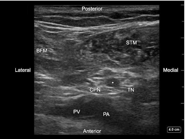
This transverse ultrasound image depicts the popliteal fossa, highlighting the anatomical arrangement for a sciatic nerve block. The imaging shows a 'honeycomb' echotexture characteristic of peripheral nerves. The tibial nerve (TN) is positioned medially and the common peroneal nerve (CPN) laterally, just distal to the sciatic nerve bifurcation. Within the paraneural sheath between these two nerves, a distinct hypoechoic, round arterial structure (marked with an asterisk) is visible. Muscular landmarks include the biceps femoris muscle (BFM) located laterally and the semitendinosus muscle (STM) positioned posteriorly and medially. Deep (anterior) to the neural structures, the popliteal artery (PA) and popliteal vein (PV) are identified, with the vein situated lateral to the artery. The image serves as an educational reference for regional anesthesia, emphasizing the importance of identifying anatomical variants, such as this inter-neural artery, to avoid vascular puncture during ultrasound-guided nerve blocks.
"sciatic nerve block" AND "popliteal" AND analgesia
ankle block five nerves deep peroneal sural posterior tibial superficial peroneal technique cross section
A composite medical educational figure demonstrating ultrasound-guided ankle block techniques for five terminal nerves. A central cross-sectional anatomical diagram of the ankle identifies needle trajectories for the deep peroneal (1), superficial peroneal (2), sural (3), posterior tibial (4), and saphenous (5) nerves. Surrounding this are five numbered panels, each pairing a high-frequency ultrasound scan with a clinical photograph of the transducer and needle placement. (1) Deep Peroneal Nerve (DPN) shown lateral to the anterior tibial artery (ATA) over the tibia. (2) Superficial Peroneal Nerve (SPN) visualized as hyperechoic clusters in the subcutaneous tissue superficial to the fascia near the fibula. (3) Sural Nerve (SUN) identified adjacent to the small saphenous vein (V). (4) Posterior Tibial Nerve (PTN) shown posterior to the posterior tibial artery (PTA) and veins (PTV) at the medial malleolus, exhibiting a classic honeycomb echotexture. (5) Saphenous Nerve (SAN) demonstrated adjacent to the great saphenous vein (SV) over the medial tibia. This resource is designed for anesthesiology training and regional anesthesia protocol development.
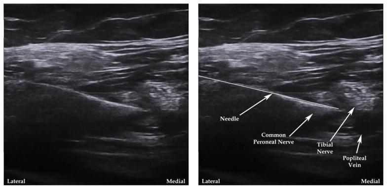
Two side-by-side ultrasound images demonstrate a regional anesthesia technique for a popliteal fossa nerve block. The diagnostic images show a transverse cross-section of the posterior knee anatomy. The left image is unannotated, while the right image includes labels and pointers for anatomical orientation. From a lateral to medial orientation, the hyperechoic structures identified include the Common Peroneal Nerve and the Tibial Nerve. Further medial and deep is the Popliteal Vein, appearing as a more hypoechoic vascular structure. A linear, hyperechoic needle is visible entering from the lateral aspect using an in-plane approach, with its tip directed toward the space between the Common Peroneal and Tibial nerves. This visual serves as an educational guide for ultrasound-guided peripheral nerve blocks, illustrating the target nerves' relationship to vascular landmarks and the proper needle trajectory to avoid vascular puncture while ensuring anesthetic deposition near the sciatic nerve bifurcation.
subgluteal sciatic nerve block ultrasound ischial tuberosity gluteus maximus
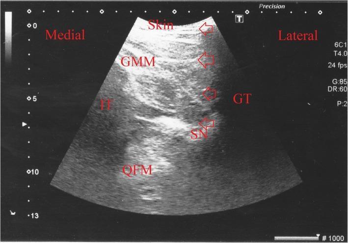
This diagnostic ultrasound image demonstrates the posterior subgluteal approach for a sciatic nerve block in a transverse (short-axis) view. The image illustrates key anatomical landmarks including the Gluteus Maximus Muscle (GMM) superficial to the deep structures, the Greater Trochanter (GT) laterally, and the Ischial Tuberosity (IT) medially. Deep to the GMM and between the GT and IT lies the Quadratus Femoris Muscle (QFM). The Sciatic Nerve (SN) is identified as a hyperechoic oval structure situated in the fascial plane between the GMM and QFM. Red arrows track the needle trajectory from the lateral-superior aspect toward the target nerve, while white triangles highlight the needle tip. A hypoechoic area labeled 'LA' indicates the distribution of local anesthetic surrounding the nerve. This visual serves as a procedural guide for regional anesthesia, highlighting the importance of real-time ultrasound guidance to ensure precise needle placement and adequate spread of anesthetic while avoiding vascular or bony structures.
This diagnostic ultrasound image demonstrates the anatomical landmarks for a subgluteal sciatic nerve block using a curved array transducer. The image shows a transverse view of the posterior hip region. Superficial layers consist of hyperechoic subcutaneous fat and fascia immediately below the transducer surface. Deep to the fascia is the gluteus maximus muscle, characterized by an intermediate echogenic texture. In the mid-to-deep field, distinct hyperechoic bony landmarks are visible: the ischial tuberosity and the greater trochanter, which create significant posterior acoustic shadowing. The sciatic nerve is situated in the fascial plane deep to the gluteus maximus and superficial to the quadratus femoris muscle, typically appearing as an oval or elliptical structure with a honeycomb or speckled echotexture. The image serves as an educational tool for ultrasound-guided regional anesthesia, illustrating the target plane for local anesthetic injection during an out-of-plane approach for treating lower extremity orthopedic injuries.
SCIATIC NERVE BLOCK | POPLITEAL NERVE BLOCK | ANKLE BLOCK
PART A: SCIATIC NERVE — ANATOMY
1.1 Origin and Roots
SCIATIC NERVE:
━━━━━━━━━━━━━━━━━━━━━━━━━━━━━━━━━━━━━━━━━━━━━━━━━━━
Origin: LUMBOSACRAL PLEXUS
Roots:  L4, L5, S1, S2, S3
        (Posterior divisions → common peroneal component)
        (Anterior divisions → tibial component)
        ↓
Exits pelvis through GREATER SCIATIC FORAMEN
  (below piriformis — "infrapiriform foramen")
        ↓
Enters POSTERIOR THIGH between:
  - Greater trochanter (lateral)
  - Ischial tuberosity (medial)
  Sciatic nerve = midpoint between these two
        ↓
Travels in POSTERIOR COMPARTMENT OF THIGH
  (deep to gluteus maximus → between hamstrings)
  → Innervates hamstrings + hip adductors (partial)
        ↓
BIFURCATES in POPLITEAL FOSSA (or distal thigh)
  → TIBIAL NERVE (L4–S3) — medial, larger
  → COMMON PERONEAL NERVE (L4–S2) — lateral, smaller
━━━━━━━━━━━━━━━━━━━━━━━━━━━━━━━━━━━━━━━━━━━━━━━━━━━
1.2 Motor Innervation
| Muscle Group | Via |
|---|---|
| Hamstrings (biceps femoris, semitendinosus, semimembranosus) | Sciatic nerve (proximal) |
| Short head of biceps femoris | Common peroneal component |
| All muscles below knee (anterior, posterior, lateral compartments) | Tibial + common peroneal branches |
1.3 Sensory Coverage
SCIATIC NERVE SENSORY TERRITORY:
─────────────────────────────────────────────────────────────
ENTIRE LEG, ANKLE, AND FOOT — except:
  ✗ Medial leg, medial ankle, medial foot → SAPHENOUS nerve
  ✗ Posterior thigh → PFCN (posterior femoral cutaneous nerve)
─────────────────────────────────────────────────────────────
Tibial nerve: posterior leg, heel, sole of foot
Common peroneal: lateral leg, dorsum of foot, web spaces
Sural nerve: lateral foot (from both tibial + common peroneal)
─────────────────────────────────────────────────────────────
1.4 Mnemonic: Sciatic Nerve Roots
"L4, L5, S1, S2, S3" — "Let 4 Little Sisters Sing Songs" (L4, L5, S1, S2, S3)
1.5 Key Anatomical Relations at Different Levels
| Level | Sciatic Nerve Relations |
|---|---|
| Exit from pelvis | Below piriformis; above superior gemellus; between GT and IT |
| Subgluteal | Deep to gluteus maximus; superficial to quadratus femoris; between GT and IT |
| Mid-thigh | Posterior compartment, under long head of biceps femoris |
| Popliteal fossa | Bifurcates into tibial (medial) + common peroneal (lateral); superficial and lateral to popliteal artery |
PART B: APPROACHES TO SCIATIC NERVE BLOCK
Summary Table: All Approaches
| Approach | Level | Position | Advantages | Best Indication |
|---|---|---|---|---|
| Parasacral | Sacral plexus (proximal) | Lateral decubitus | Blocks all plexus branches including PFCN | Whole limb surgery; reliable PFCN coverage |
| Classic Labat / Gluteal | Subgluteal (deep) | Lateral / prone | Covers PFCN, hamstrings | Rarely used — deep, poor US |
| Subgluteal (modified) | Below gluteus maximus | Sim's / prone | US-guided, includes PFCN; hamstrings | Knee surgery + below-knee amputation |
| Popliteal | Popliteal fossa | Prone / lateral / supine (leg up) | Spares hamstrings; excellent for foot/ankle | Foot and ankle surgery |
| Anterior | Mid-thigh (anterior) | Supine | No repositioning needed; leg in traction | Trauma; difficult positioning |
| Lateral (thigh) | Posterior thigh via lateral | Supine | Foot/ankle surgery without prone | Day surgery |
Approach 1: CLASSIC GLUTEAL (LABAT) APPROACH
- Patient: lateral decubitus (operative side up)
- Landmarks: PSIS → greater trochanter (draw line); midpoint of this line → drop perpendicular 3–5 cm (Labat's point)
- Insert 10 cm insulated needle perpendicular; advance until twitch of foot/toes at < 0.5 mA
- Volume: 20–25 mL LA
- Disadvantage: very deep (8–10 cm), poor US visualisation, proximity to pelvic viscera
Approach 2: SUBGLUTEAL APPROACH (Current Standard)
Position: Sim's position (semi-prone) or prone
Landmarks
- Line between ischial tuberosity (IT) and greater trochanter (GT)
- Nerve lies at the midpoint between IT and GT, deep to gluteus maximus, superficial to quadratus femoris
Sonoanatomy
SUBGLUTEAL US (Transverse, Curved Probe):
─────────────────────────────────────────────────
[GLUTEUS MAXIMUS] ← hyperechoic fascia, large superficial muscle
[ISCHIAL TUBEROSITY] ← medial bony landmark (acoustic shadow)
[GREATER TROCHANTER] ← lateral bony landmark (acoustic shadow)
[QUADRATUS FEMORIS] ← deep muscle, "floor" between the two bones
[SCIATIC NERVE] ← between IT and GT, deep to glut. max.,
                  SUPERFICIAL to quadratus femoris
                  Hyperechoic, flat oval / triangular, honeycomb
[INFERIOR GLUTEAL A/V] ← medial to nerve (colour Doppler)
─────────────────────────────────────────────────
Technique
STEP 1: Probe transverse, over midpoint IT-GT
STEP 2: Identify GT (lateral acoustic shadow) + IT (medial acoustic shadow)
STEP 3: Gluteus maximus (superficial) → Quadratus femoris (deep)
STEP 4: Sciatic nerve = hyperechoic oval in fascial layer between the two
STEP 5: Colour Doppler — identify inferior gluteal vessels (avoid)
STEP 6: Insert needle lateral to medial (in-plane); 10 cm 22G needle
STEP 7: Advance to circumferential LA spread around sciatic nerve
STEP 8: Inject 20–25 mL LA; "donut sign" = success
STEP 9: Nerve stimulation supplement: foot plantar/dorsiflexion < 0.5 mA
Drug and Onset
- Ropivacaine 0.5%, 20–25 mL | Onset 20–30 min | Duration 12–18 h
- Nerve stimulator endpoint: foot inversion (tibial) or dorsiflexion/eversion (common peroneal)
Approach 3: ANTERIOR SCIATIC NERVE BLOCK
Indication
- Supine patient who cannot be repositioned (trauma, traction, obese patient, bilateral blocks)
Anatomy
- At mid-thigh level, accessed via anteromedial thigh, medial to femoral vessels
- Nerve is lateral to the femoral vessels in this projection
- Deep to gracilis and adductor magnus
Technique
- Supine position; identify femoral artery/ASIS
- Insert needle medial to femoral vessels (at level of lesser trochanter)
- Direct posteromedially with nerve stimulator guidance
- Technically challenging — long needle path, proximity to femoral vessels; US can assist
PART C: POPLITEAL SCIATIC NERVE BLOCK
2.1 Introduction
- Sparing hamstring function (no effect above knee)
- Allowing knee flexion — patients can ambulate with crutches post-op
- When combined with saphenous nerve block, achieves complete below-knee anaesthesia
2.2 Popliteal Fossa Anatomy
POPLITEAL FOSSA — CONTENTS AND BOUNDARIES:
━━━━━━━━━━━━━━━━━━━━━━━━━━━━━━━━━━━━━━━━━━━━━━━━━━━
BOUNDARIES:
  Superolateral: Biceps femoris tendon
  Superomedial: Semitendinosus + Semimembranosus
  Inferolateral: Lateral head of gastrocnemius
  Inferomedial: Medial head of gastrocnemius

CONTENTS (from deep to superficial / lateral to medial):
  Popliteal ARTERY (deepest — anterior)
  Popliteal VEIN (behind artery, compressible)
  TIBIAL NERVE (largest branch, medial, superficial to vessels)
  COMMON PERONEAL NERVE (lateral, exits via fibular head)
  [Sciatic nerve = tibial + CPN together, in paraneural sheath]
  PFCN (superficial — sensory to posterior thigh/knee)
  Popliteal lymph nodes, fat

KEY POINT: Sciatic nerve is SUPERFICIAL and LATERAL to the
           popliteal vessels at the popliteal crease level
━━━━━━━━━━━━━━━━━━━━━━━━━━━━━━━━━━━━━━━━━━━━━━━━━━━
2.3 Level of Bifurcation
- Sciatic nerve bifurcates into tibial + common peroneal within or just proximal to the popliteal fossa (variable — usually 5–10 cm above popliteal crease)
- Key principle: Block PROXIMAL to the bifurcation for reliable effect on both branches
- US allows scanning proximally to find the point where the two components are still wrapped in a common paraneural sheath (Vloka's sheath) — single injection covers both
2.4 Sonoanatomy
POPLITEAL FOSSA US (Transverse, Linear Probe):
─────────────────────────────────────────────────────────────
[BICEPS FEMORIS] ← lateral
[SEMITENDINOSUS / SEMIMEMBRANOSUS] ← medial
[POPLITEAL ARTERY] ← deep (anterior), anechoic, pulsatile
[POPLITEAL VEIN] ← lateral and superficial to artery, compressible
[TIBIAL NERVE] ← superficial to vessels, medial, larger, hyperechoic
[COMMON PERONEAL NERVE] ← lateral to tibial, smaller, exits toward fibular head
[SCIATIC NERVE (undivided)] ← scan proximally — oval "bilobed" honeycomb,
                               superficial + lateral to vessels
─────────────────────────────────────────────────────────────
"BILOBED SIGN" = TN + CPN within common sheath = sweet spot for injection
─────────────────────────────────────────────────────────────
2.5 Popliteal Block Technique
Position Options
- Prone — classical; best US view; needle from posterior
- Lateral decubitus — operative side up
- Supine with leg elevated (leg raised on pillows/padded stand) — convenient, no repositioning
Step-by-Step US-Guided Popliteal Block
POPLITEAL SCIATIC BLOCK — US GUIDED (Posterior or Lateral):
━━━━━━━━━━━━━━━━━━━━━━━━━━━━━━━━━━━━━━━━━━━━━━━━━━━━━━
PROBE:  Linear high-frequency (10–15 MHz)
NEEDLE: 50–100mm, 22G insulated stimulating needle

STEP 1: Place probe transverse at popliteal crease
        → Identify popliteal artery (pulsatile, deep)
        → Popliteal vein (compressible, lateral)
        → Tibial nerve (hyperechoic oval, superficial to vessels)

STEP 2: Slide probe PROXIMALLY (toward thigh)
        → Watch TN + CPN come together into BILOBED OVAL
        → This is the sciatic nerve just above its bifurcation
        → Within Vloka's (paraneural) sheath

STEP 3: Identify the interneural groove (cleft between TN and CPN)
        → Target this space for interneural injection

STEP 4: Insert needle IN-PLANE from lateral to medial
        (or OOP if using nerve stimulator)
        → Advance tip between TN and CPN at their junction

STEP 5: Aspirate → Inject 1 mL to confirm spread within sheath
        → "Opening" between TN and CPN = correct plane

STEP 6: Inject 20–25 mL LA in incremental boluses of 5 mL
        → Observe LA tracking into both TN and CPN
        → "Donut sign" = circumferential spread = success

STEP 7: Confirm with nerve stimulator (optional):
        Plantar flexion (tibial) or Dorsiflexion/eversion (CPN) at <0.5 mA

LATERAL APPROACH (supine, leg elevated):
  → Same technique but probe/needle from LATERAL aspect
  → Transducer on lateral posterior thigh
  → Needle in-plane lateral to medial
━━━━━━━━━━━━━━━━━━━━━━━━━━━━━━━━━━━━━━━━━━━━━━━━━━━━━━
Key Point (Miller's 10e): The TN lies posterior to the popliteal artery at the popliteal crease — this is a reliable starting point when imaging is difficult. Slide proximally until TN and CPN come together into the bilobed "honeycomb" structure.
2.6 Nerve Stimulator Endpoints
| Response | Nerve | Interpretation |
|---|---|---|
| Plantar flexion (foot down) | Tibial | Acceptable — inject here |
| Inversion | Tibial | Acceptable |
| Dorsiflexion (foot up) | Common peroneal | Acceptable |
| Eversion | Common peroneal | Acceptable |
| Knee flexion | Hamstrings (too proximal) | Reposition distally |
| No response | Too distal or off-target | Reposition |
2.7 Drug and Doses
| Drug | Concentration | Volume | Duration |
|---|---|---|---|
| Ropivacaine | 0.5% | 20–25 mL | 12–18 h |
| Bupivacaine | 0.25–0.5% | 20–25 mL | 14–20 h |
| Levobupivacaine | 0.5% | 20–25 mL | 14–18 h |
| Adjuvants | Dexamethasone 4–8 mg + Dexmedetomidine 50–100 mcg | Extend duration by 4–8 h | (PMID: 38253609) |
Recent Evidence (Eur J Anaesthesiol 2024, PMID: 37972929): In a RCT of forefoot surgery, popliteal sciatic block provided equivalent analgesia duration to ankle block with fewer complications and superior patient satisfaction, supporting popliteal block as the preferred approach for forefoot surgery.
2.8 Popliteal Block Complications
| Complication | Cause | Prevention |
|---|---|---|
| Popliteal vessel injury | Major site-specific risk; artery deep to nerve | Colour Doppler; aspirate; stay superficial to vessels |
| Common peroneal nerve injury | More at risk (thinner sheath) | Circumneural, not intraneural injection |
| Foot drop | CPN injury → weakness of dorsiflexion + eversion | Avoid intraneural; stop if pain on injection |
| Haematoma | Popliteal vascular puncture | Doppler identification |
| LAST | Vascular injection | Aspiration; incremental injection; Intralipid ready |
| Incomplete block | Injection distal to bifurcation | Scan proximally for bilobed appearance |
PART D: ANKLE BLOCK — COMPLETE 5-NERVE TECHNIQUE
3.1 Introduction
- Blocks 5 terminal nerves supplying the foot at the level of the malleoli
- 4 nerves are sciatic branches; 1 nerve (saphenous) is a femoral nerve branch
- Provides complete foot anaesthesia without tourniquet issues
- No motor block of leg — patient can flex knee
- Limitation: No tourniquet analgesia above the ankle — cannot use thigh tourniquet comfortably
3.2 Five Nerves of the Foot
ANKLE BLOCK — 5 NERVES:
Mnemonic: "DEPSS" — Deep peroneal, Extra (saphenous), Posterior tibial, Sural, Superficial peroneal

or: Think CLOCKWISE around the ankle:
  12 o'clock = Deep Peroneal (anterior, between tendons)
  2 o'clock  = Saphenous (anteromedial, beside GSV)
  5 o'clock  = Posterior Tibial (posteromedial, behind PTA)
  7 o'clock  = Sural (posterolateral, beside small saphenous vein)
  10 o'clock = Superficial Peroneal (anterolateral, subcutaneous)
| # | Nerve | Origin | Location at Ankle | Coverage | Technique |
|---|---|---|---|---|---|
| 1 | Deep Peroneal | Common peroneal | Between EHL and EDL tendons; LATERAL to dorsalis pedis artery | First dorsal web space; toe extensors | Deep injection lateral to DP pulse; 5 mL |
| 2 | Superficial Peroneal | Common peroneal | Subcutaneous anterolateral, over extensor retinaculum | Dorsum of foot (most) — all toes except 1st web space | Subcutaneous band, lateral malleolus → EHL; 5 mL |
| 3 | Posterior Tibial | Tibial | POSTERIOR to medial malleolus, beside posterior tibial artery (PTA) | Sole of foot — medial + lateral plantar + calcaneal | Injection posterior to PTA; 5 mL deep to flexor retinaculum |
| 4 | Sural | Tibial + CPN | Posterior to lateral malleolus, beside small saphenous vein | Lateral foot, lateral heel, 5th toe | Subcutaneous, between Achilles and lateral malleolus; 5 mL |
| 5 | Saphenous | Femoral (L3, L4) | ANTERIOR to medial malleolus, beside great saphenous vein | Medial ankle, medial arch | Subcutaneous wheal anterior to medial malleolus; 5 mL |
3.3 Technique — Step by Step (Landmark-Based)
ANKLE BLOCK TECHNIQUE (Landmark + US guidance):
━━━━━━━━━━━━━━━━━━━━━━━━━━━━━━━━━━━━━━━━━━━━━━━━━━━
POSITION: Supine, foot neutral (slight dorsiflexion for DP nerve)
NEEDLE: 25G short bevel for all; 22G for posterior tibial (deeper)
ALL VOLUMES: 5 mL per nerve = 25 mL total

━━━━━━━━━━━━━━━━━━━━━━━━━━━━━━━━━━━━━━━━━━━━━━━━━━━
1. DEEP PERONEAL NERVE:
   Identify groove between EHL (medial) and EDL tendons
   (OR just lateral to dorsalis pedis artery pulse)
   Insert perpendicular; contact tibia; withdraw slightly
   Inject 5 mL lateral to dorsalis pedis artery

2. SUPERFICIAL PERONEAL NERVE:
   From same needle insertion site (deep peroneal entry)
   Redirect needle LATERALLY, subcutaneously
   Extend subcutaneous wheal toward lateral malleolus
   Inject 5 mL (field block in subcutaneous plane)

3. SAPHENOUS NERVE:
   From same needle site → redirect MEDIALLY
   Subcutaneous wheal from dorsalis pedis entry → medial malleolus
   Inject 5 mL in subcutaneous band (targets GSV + nerve)

4. POSTERIOR TIBIAL NERVE:
   New needle insertion posterior to medial malleolus
   Palpate/US: posterior tibial artery pulse
   Insert needle JUST POSTERIOR to PTA
   Advance deep to flexor retinaculum
   Inject 5 mL (can feel "give" as retinaculum is penetrated)

5. SURAL NERVE:
   New needle insertion posterior to lateral malleolus
   Between Achilles tendon and lateral malleolus
   Subcutaneous injection 5 mL (targets small saphenous vein + nerve)
━━━━━━━━━━━━━━━━━━━━━━━━━━━━━━━━━━━━━━━━━━━━━━━━━━━
TOTAL: 5 nerves × 5 mL = 25 mL
3.4 Drugs for Ankle Block
| Drug | Concentration | Vol/nerve | Total | Duration |
|---|---|---|---|---|
| Ropivacaine | 0.5% | 5 mL | 25 mL | 8–12 h |
| Bupivacaine | 0.25–0.5% | 5 mL | 25 mL | 10–14 h |
| Lignocaine | 1–2% | 5 mL | 25 mL | 2–4 h (short case) |
WARNING — Epinephrine contraindicated in ankle block: No vasoconstrictors at ankle level — end-arterial circulation in toes; risk of digital ischaemia. Also avoid excessive volumes.
3.5 Ankle Block vs. Popliteal Sciatic Block
| Feature | Ankle Block | Popliteal Sciatic Block |
|---|---|---|
| Approach | 5 separate injections | Single injection |
| Thigh tourniquet | Not possible | Possible |
| Ankle tourniquet | Possible | Possible |
| Coverage | Foot only | Entire leg below mid-thigh |
| Onset | Slower (5 separate sites) | Single onset |
| Motor block | Minimal (no leg muscles) | Foot and ankle muscles blocked |
| Hamstrings | Spared | Spared (popliteal approach) |
| Patient comfort | 5 injections — premedicate | Single injection |
| Failure rate | Higher (5 nerves; variable anatomy) | Lower with US |
| Best for | Minor foot surgery; no tourniquet need | Complex foot/ankle surgery with tourniquet |
RCT Evidence (PMID: 37972929, Eur J Anaesthesiol 2024): For forefoot surgery, popliteal block (at popliteal crease) provided longer analgesia duration and fewer complications compared with ankle block. Ankle block remains valuable for procedures not requiring tourniquet.
PART E: INDICATIONS — WHEN TO USE WHICH BLOCK
| Surgery | Recommended Block |
|---|---|
| Hallux valgus / bunion | Popliteal sciatic + saphenous or ankle block |
| Toe amputation (diabetes) | Ankle block (no tourniquet) |
| Ankle fracture/arthroplasty | Popliteal sciatic + saphenous (tourniquet) |
| Calcaneal surgery | Popliteal sciatic + saphenous |
| Achilles tendon repair | Popliteal sciatic + saphenous |
| Below-knee amputation | Subgluteal sciatic + saphenous (femoral) |
| Knee surgery (TKA) | Femoral/ACB + subgluteal or popliteal sciatic |
| Fibula free flap harvest | Popliteal sciatic + saphenous (PMID: 40483489 — liposomal bupi reduces opioid use) |
| Clubfoot correction | Popliteal sciatic + saphenous |
| Shin / tibial fracture | Popliteal sciatic + femoral |
PART F: RECENT ADVANCES (2024–2026)
-
Liposomal Bupivacaine (Exparel) in popliteal sciatic block — single injection with extended duration up to 72 hours for foot/ankle surgery; demonstrated opioid-sparing effect in free fibula flap reconstruction ([PMID: 40483489], BMC Anaesthesiol 2025)
-
Magnesium sulfate as adjuvant (PMID: 39480231, RCT 2024) — ropivacaine + MgSO4 at popliteal level significantly extended analgesia duration vs. ropivacaine alone with no increase in side effects
-
PROSPECT Guidelines (Eur J Anaesthesiol 2026, PMID: 41122054) — For hallux valgus surgery, popliteal sciatic block (with saphenous) is recommended as the primary analgesic modality; ankle block acceptable for less complex forefoot procedures
-
IPACK block (Interspace between Popliteal Artery and posterior Capsule of Knee) — US-guided; motor-sparing alternative to popliteal sciatic for posterior knee pain in TKA; can be combined with ACB for complete motor-sparing analgesia
-
Selective tibial nerve block — Posterior tibial nerve alone at popliteal fossa for posterior knee pain without causing foot drop; useful adjunct in TKA ERAS
-
Continuous popliteal catheters — For postoperative analgesia after complex foot/ankle reconstruction; ERAS protocols now recommend perineural catheters for 48–72 h; programmable infusion pumps allow home use
-
US-guided dual-injection technique — Injecting inside Vloka's sheath AND at bifurcation point significantly improves block onset and quality vs. single injection
PART G: COMPLICATIONS — ALL BLOCKS
| Complication | Block | Mechanism | Management |
|---|---|---|---|
| Foot drop | Popliteal, sciatic | CPN injury; intraneural injection | Avoid intraneural; monitor post-op |
| LAST | All | Vascular injection | Intralipid 20%; ACLS |
| Popliteal artery injury | Popliteal | Proximity of nerve to artery | Colour Doppler; careful advancement |
| Incomplete block | All | Distal injection (past bifurcation); wrong plane | Scan for bilobed sign; scan proximally |
| Digital ischaemia | Ankle block | Epinephrine / excess volume | Never use epi; limit volumes |
| Haematoma | Subgluteal, popliteal | Inferior gluteal / popliteal vessels | Direct pressure; rule out compartment syndrome |
| Hamstring weakness | Subgluteal / gluteal | Sciatic block proximal to hamstrings | Choose popliteal if ambulation desired |
| Prolonged motor block | All | Extended-release LA; overdose | Observation; reassurance; neurology if > 24 h |
PART H: CLINICAL PEARLS
-
Sciatic nerve = L4, L5, S1, S2, S3: the largest nerve in the body; contains two distinct components (tibial and peroneal) within one sheath from origin to popliteal fossa
-
Subgluteal vs. popliteal: If hamstring coverage + posterior knee analgesia is needed → subgluteal; If ambulation desired + foot/ankle only → popliteal
-
Bifurcation level is variable: usually 5–10 cm above popliteal crease; always scan proximally to find the bilobed undivided nerve for optimal single-injection coverage
-
Tibial nerve is larger, lies medial and superficial to popliteal vessels; CPN is lateral, exits laterally — this asymmetry is the key to orientation
-
Interneural injection (between TN and CPN within Vloka's sheath) → fastest onset, best spread; "opening" of the sheath between the two components is the US-guided endpoint
-
Ankle block — the big danger is epinephrine: Never use epinephrine in ankle block — end-artery territory; causes digital ischaemia
-
Posterior tibial nerve is the most important nerve to block for plantar surgery (heel pain, plantar fasciitis, forefoot plantar lesions) — sole of foot and heel
-
Sural nerve is a branch of the tibial nerve — remember: it is NOT a direct CPN branch; formed by contributions from both tibial and CPN; enters foot posterior to lateral malleolus
-
Superficial peroneal nerve supplies the dorsum of ALL toes except the first web space (that is deep peroneal territory)
-
In ankle block: only 3 needle insertions needed — (a) dorsalis pedis area [DP + SP + saphenous from same entry], (b) posterior to medial malleolus [posterior tibial], (c) posterior to lateral malleolus [sural]
PART I: VIVA QUESTIONS
- Roots: L4, L5, S1, S2, S3. Motor: hamstrings (semitendinosus, semimembranosus, biceps femoris), ischial part of adductor magnus — all distally via tibial and common peroneal branches
- Entire leg, ankle and foot except the medial leg, medial ankle and medial foot (which are saphenous nerve territory)
- The common paraneural connective tissue sheath enclosing both the tibial and common peroneal nerve components of the sciatic nerve within the popliteal fossa. Injecting inside this sheath produces circumferential LA spread to both components with a single injection. It is the "gold standard" target for popliteal sciatic block.
- Popliteal block spares the hamstrings; patient can flex knee and lift foot; allows ambulation with crutches. Subgluteal blocks hamstrings and produces complete limb weakness.
- Deep peroneal, superficial peroneal, posterior tibial, sural (all sciatic branches), and saphenous nerve (which is the only non-sciatic nerve — it is the terminal sensory branch of the femoral nerve)
- The distal arteries of the toes and forefoot are end-arteries with minimal collateral circulation. Epinephrine-induced vasoconstriction in this territory causes digital ischaemia and necrosis. Epinephrine is absolutely contraindicated in ankle blocks and digital blocks.
- Tibial component: plantar flexion or inversion at < 0.5 mA; Common peroneal component: dorsiflexion or eversion. Either is acceptable for popliteal block since both components lie within Vloka's sheath.
- The sural nerve arises from contributions of both the tibial and common peroneal nerves. It runs posterior to the lateral malleolus alongside the small saphenous vein and supplies the lateral heel and lateral foot.
- The medial leg, medial ankle, and medial foot are supplied by the saphenous nerve (terminal branch of the femoral nerve) — not the sciatic nerve. Complete below-knee anaesthesia always requires sciatic + saphenous nerve blocks together.
- At and just above the bifurcation, the tibial nerve (medial, larger) and common peroneal nerve (lateral, smaller) are visible as two hyperechoic oval structures within a common paraneural sheath, giving a bilobed or "figure-8" appearance. This is the optimal injection target — LA injected at this point spreads into both components via the common sheath.
PART J: RAPID REVISION BOX
SCIATIC NERVE BLOCK / POPLITEAL / ANKLE — RAPID REVISION
━━━━━━━━━━━━━━━━━━━━━━━━━━━━━━━━━━━━━━━━━━━━━━━━━━━━━━━━━

SCIATIC NERVE:
  Roots: L4, L5, S1, S2, S3 (lumbosacral plexus)
  Largest nerve in body; purely sensory below knee (except motor to hamstrings)
  Exits pelvis: INFRAPIRIFORM foramen
  Bifurcates → TIBIAL (medial, larger) + COMMON PERONEAL (lateral)
    Usually 5–10 cm above popliteal crease

SENSORY TERRITORY:
  All leg/ankle/foot EXCEPT medial leg/ankle/foot (saphenous = femoral nerve)
  Complete block below knee = SCIATIC + SAPHENOUS

APPROACHES:
  Parasacral → covers PFCN + all plexus branches (most proximal)
  Subgluteal → below gluteus maximus, midpoint IT–GT, deep to glut max,
               superficial to quadratus femoris; 20–25 mL
  Popliteal → most used; posterior fossa; bilobed sign; spares hamstrings
  Anterior → supine; trauma/traction cases

POPLITEAL FOSSA (medial → lateral):
  Popliteal A → Popliteal V → TIBIAL N → CPN
  Nerve is SUPERFICIAL and LATERAL to popliteal vessels
  Scan PROXIMALLY for "bilobed" undivided nerve in Vloka's sheath
  Needle: 22G 50–100mm; LA: Ropivacaine 0.5%, 20–25 mL

ANKLE BLOCK — 5 NERVES ("DEPSS"):
  Deep Peroneal: lateral to dorsalis pedis A → 1st web space
  Superficial Peroneal: subcutaneous anterolateral → dorsum foot
  Posterior Tibial: POSTERIOR to medial malleolus (with PTA) → sole
  Sural: posterior to lateral malleolus (with SSV) → lateral foot
  Saphenous: ANTERIOR to medial malleolus (with GSV) → medial ankle
  Volume: 5 mL × 5 = 25 mL | ⚠️ NO EPINEPHRINE (digital ischaemia)

KEY DIFFERENCES (Popliteal vs. Ankle):
  Popliteal: tourniquet OK; fewer injections; covers ankle tourniquet;
             blocks foot + ankle muscles; onset faster
  Ankle: 5 injections; no tourniquet above ankle; minimal motor;
         good for isolated toe/forefoot surgery

RECENT EVIDENCE (2024–2026):
  Liposomal bupivacaine popliteal block → up to 72 h analgesia (PMID: 40483489)
  MgSO4 adjuvant extends popliteal block duration (PMID: 39480231)
  PROSPECT 2026: Popliteal sciatic preferred over ankle for hallux surgery (PMID: 41122054)
  IPACK block = motor-sparing popliteal alternative for TKA posterior pain

VLOKA'S SHEATH: Common paraneural sheath around TN + CPN in popliteal fossa
  → Target of single-injection popliteal block
  → "Bilobed sign" = TN + CPN within sheath = sweet spot
━━━━━━━━━━━━━━━━━━━━━━━━━━━━━━━━━━━━━━━━━━━━━━━━━━━━━━━━━
Updated Tracker
✅ DISCUSSED (14 topics)
| # | Topic | Paper Reference |
|---|---|---|
| 1 | Brachial Plexus | Sec 15 P1/Q5 |
| 2 | Erector Spinae Plane Block | Sec 15 P4/Q4 |
| 3 | Serratus Anterior Plane Block | Sec 15 P4 |
| 4 | Paravertebral Block | Sec 11 P2/Q12 |
| 5 | Coeliac Plexus Block | Sec 15 P1/Q1; P2/Q6 |
| 6 | Stellate Ganglion Block | Sec 15 P1/Q8; P2/Q7 |
| 7 | TAP Block | Sec 15 P1/Q2; P4/Q2 |
| 8 | Quadratus Lumborum Block | Sec 15 P1/Q7; P2/Q10 |
| 9 | Femoral Nerve Block | Sec 15 P3/Q4 |
| 10 | Adductor Canal Block | Sec 15 P3/Q5 |
| 11 | PENG Block | Sec 15 P2/Q9 |
| 12 | Obturator Nerve Block | Sec 15 P3/Q7 |
| 13 | Saphenous Nerve Block | Supplementary |
| 14 | Sciatic / Popliteal / Ankle Block | Sec 15 P3/Q1 |
- Saphenous = only non-sciatic nerve at ankle (femoral nerve origin)
- Vloka's sheath + bilobed sign = the single-injection rationale
- NO epinephrine in ankle block (digital ischaemia)
- Posterior tibial is posterior to medial malleolus; saphenous is anterior
- Popliteal block spares hamstrings — subgluteal does NOT