
Traction
What context are you asking about "Traction"?
skeletal traction pin femur orthopedic
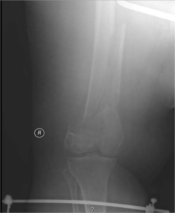
This diagnostic image is an anteroposterior (AP) radiograph of the right lower extremity, specifically the knee and distal femur, in an adult patient. The image demonstrates a complex, comminuted fracture of the distal femur. Key radiographic features include significant shortening and impaction of the femoral shaft into the supracondylar region, with a notable varus alignment of the distal fracture fragment. The distal femoral fragment is angled medially relative to the proximal femoral shaft. In the lower portion of the radiograph, elements of a skeletal traction system are visible, including a tibial traction pin (Steinmann pin) passing through the proximal tibia and secured to a metallic traction bow. The soft tissue envelope appears markedly thickened, consistent with clinical context of morbid obesity and traumatic swelling. This visual demonstrates the radiographic appearance of a high-energy femoral fracture and the application of skeletal traction as an initial orthopedic management strategy for length maintenance and fracture reduction.
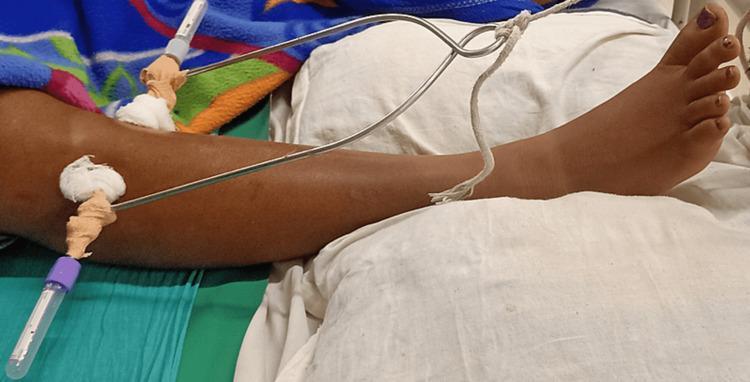
A clinical photograph of a human lower extremity illustrating a proximal skeletal traction setup. The image shows a metal Steinman pin or Kirschner wire inserted transversely through the proximal tibia or distal femur region of the leg. The pin is secured on both ends with protective caps and padded with gauze and adhesive tape at the entry and exit sites to maintain sterility and prevent skin irritation. A metal traction stirrup is attached to the pin, extending distally over the lower leg. A white traction rope is tied to the central eyelet of the stirrup, facilitating the application of longitudinal force for fracture reduction or deformity correction. The leg is positioned supine on hospital linens, and the foot is visible in a neutral to slightly plantarflexed position. This procedural image demonstrates the mechanical components and anatomical placement necessary for stabilizing lower limb injuries or managing pre-operative orthopedic conditions like hip flexion deformities.
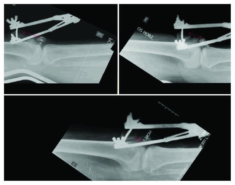
This set of three lateral-view radiological images (X-rays) demonstrates the management of a chronic patellar fracture with significant diastasis and subsequent pseudoarthrosis. The images highlight a transskeletal patellar traction assembly utilizing an external fixation device and a transversely inserted Steinmann pin in the proximal patellar pole. Superimposed red digital measurement lines quantify the distance between the proximal and distal bone fragments, showing a serial reduction in the gap from an initial wide diastasis to 1.24 cm in the final panel. The radiographs capture the knee in extension, illustrating the orthopedic approach to preoperative fracture reduction via progressive traction. Key anatomical structures visible include the femur, tibia, and the distracted patellar fragments. This visual material is highly relevant for orthopedic surgical training, specifically regarding the treatment of neglected patellar fractures and the use of external skeletal traction for soft tissue and bone mobilization.
Orthopedic Traction
Definition
- Bailey and Love's Short Practice of Surgery 28th Ed., p. 5126
Types of Traction
1. Skin Traction (Cutaneous / Buck's Traction)
- Adequate only for small traction forces
- Risks include skin damage, sensitivity reactions, blistering, and necrosis - especially in elderly patients with fragile skin
- Not suitable for long-duration or high-load traction
2. Skeletal Traction
- Distal femur
- Proximal tibia
- Calcaneus
- Unstable pelvic ring and acetabular fractures
- Femoral shaft fractures
- Intra-articular fracture fragments (to offload cartilage and prevent pressure necrosis)
- Polytrauma patients not cleared for surgery
- Acute management of cervical spine fractures
- Sabiston Textbook of Surgery, p. 576-590
- Rockwood and Green's Fractures in Adults 10th Ed., p. 706-744
Fixed vs. Balanced (Sliding) Traction
| Feature | Fixed Traction | Balanced/Sliding Traction |
|---|---|---|
| Counterforce | Against the patient's own body (e.g., ischial tuberosity via Thomas splint ring) | Weight of the patient + friction against the bed |
| Mobility | Patient can be transported | Patient confined to bed |
| Joint movement | Limited | Often possible with careful design |
| Example | Thomas splint | Braun traction, Hamilton-Russell traction |
- Pye's Surgical Handicraft 22nd Ed., p. 61-84
Methods and Named Systems
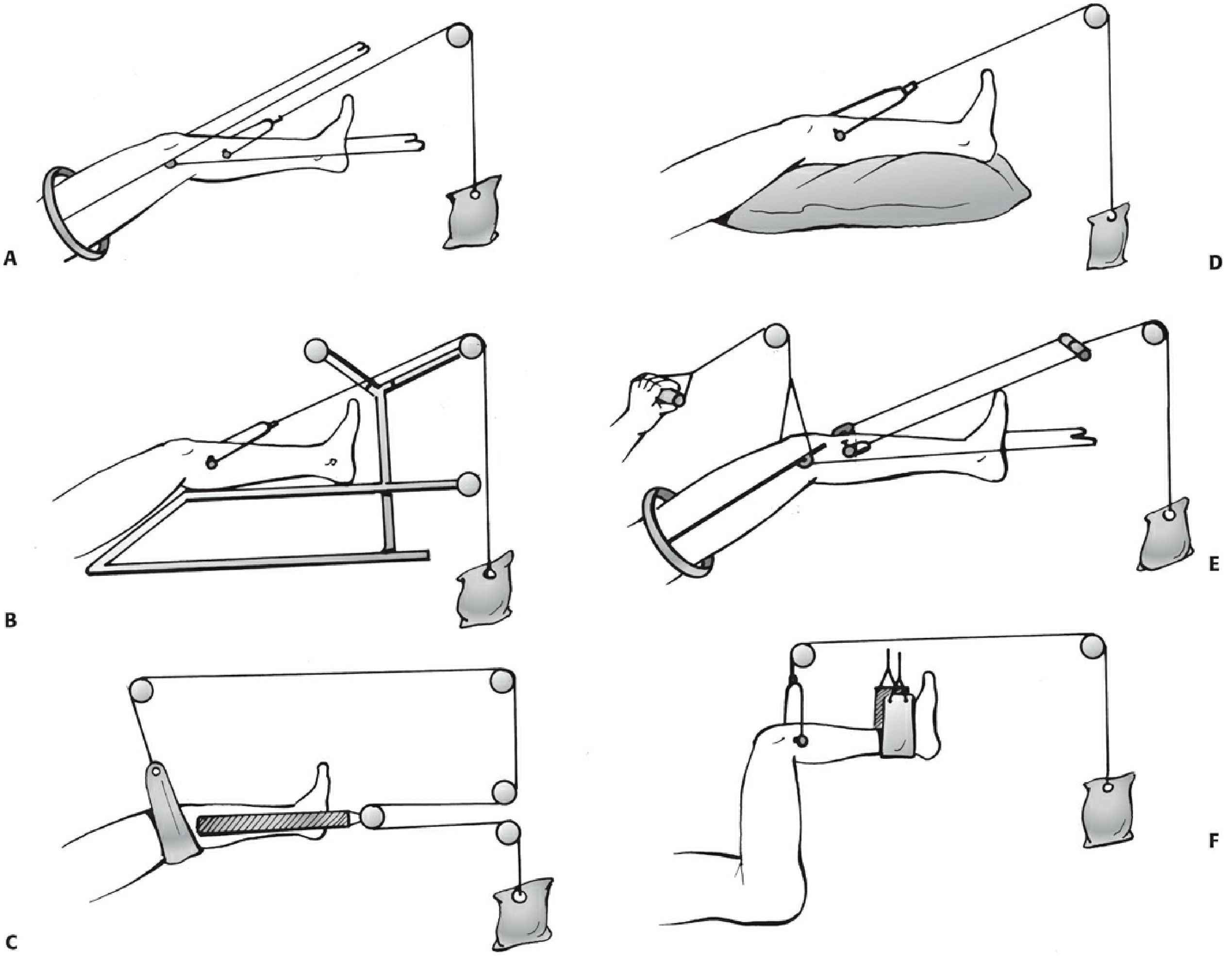
- Rockwood and Green's Fractures in Adults 10th Ed., p. 718-732
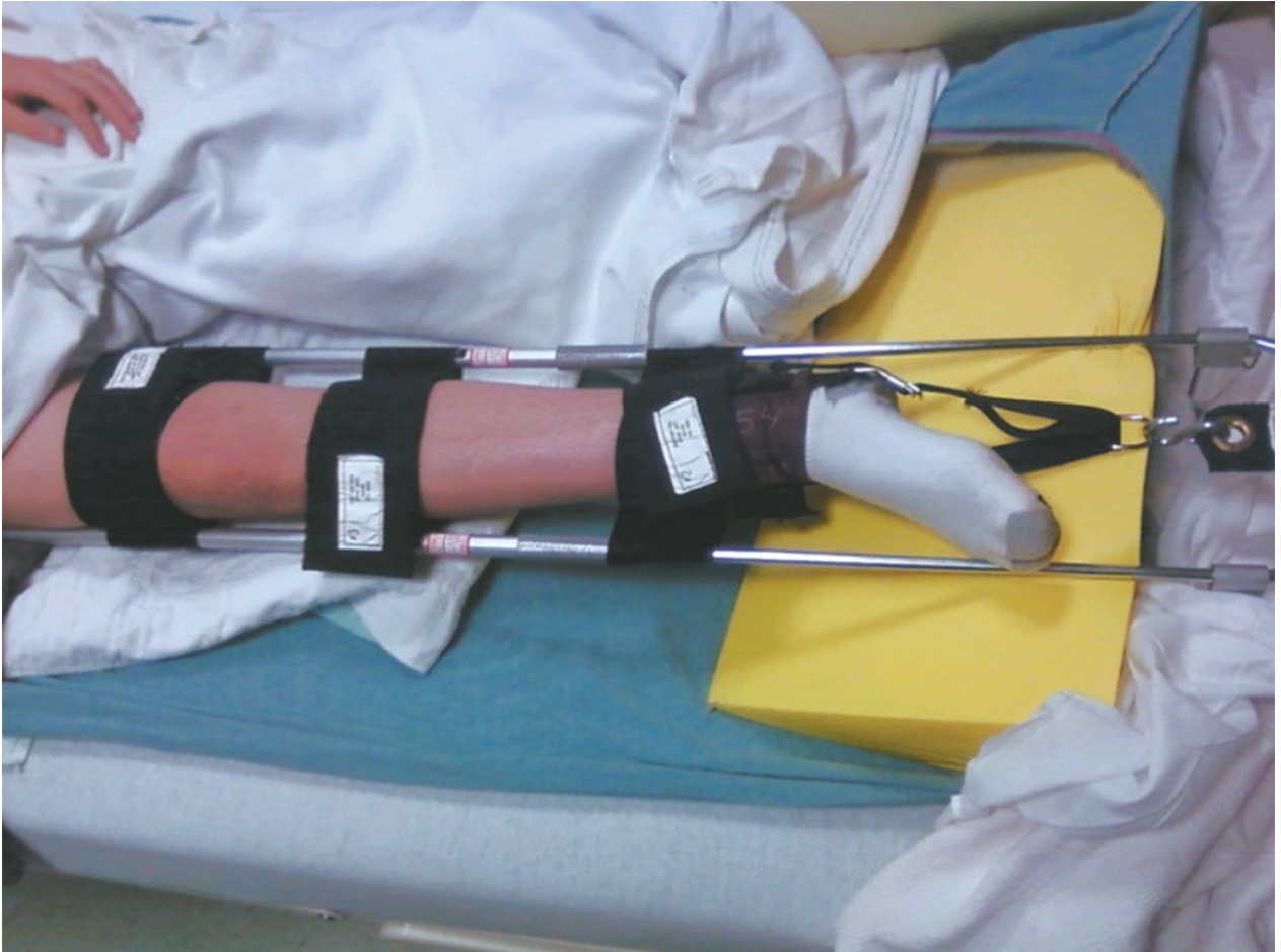
Traction Splints (Prehospital)
Advantages and Disadvantages of Traction
| Advantages | Disadvantages |
|---|---|
| No wound in the zone of injury | Restricts patient mobility |
| No interference with fracture site | Expensive in hospital time |
| Materials are cheap | Skin pressure complications |
| Adjustable | Pin-site infection |
| Thromboembolic complications |
- Bailey and Love's Short Practice of Surgery 28th Ed. (Table 32.5)
Current Role
- Resource-limited settings where fixation is unavailable
- Prehospital first aid before transfer to a surgical facility
- Cervical spine fractures (acute management)
- Polytrauma patients awaiting clearance for surgery
- Pediatric patients (especially 90-90 traction for femoral fractures)
-
Malunion/nonunion requiring reoperation: 11-29%
-
Shortening >2 cm: 14-30%
-
Refracture: 4-17%
-
Knee stiffness (the most significant complication): 30-50%
-
Decubitus ulcers
-
Psychological problems, loss of employment (in working-age patients)
-
Rockwood and Green's Fractures in Adults 10th Ed., p. 734-738