
rotatory cuff
rotator cuff anatomy muscles tendons shoulder
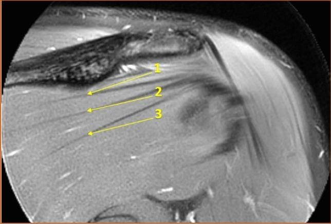
This diagnostic image is a T2-weighted magnetic resonance image (MRI) using a spectral adiabatic inversion recovery (SPAIR) sequence in a coronal section. It demonstrates the normal anatomy and variations of the infraspinatus muscle of the rotator cuff. The visual focus is on the numerous dark, linear, hypointense bands labeled with numerical arrows (1, 2, 3), which represent intramuscular tendons. These tendons are composed of dense connective tissue and are seen running longitudinally, generally parallel to the muscle fibers. The superior border of the image shows the scapular spine, which acts as a landmark for the 'central measuring point' under the deltoid tubercle. This imaging modality and view are used in musculoskeletal radiology to assess the internal architecture of the rotator cuff muscles, which can be relevant for evaluating muscular health, volume, and potential tendinopathy or fiber disruption in the shoulder.
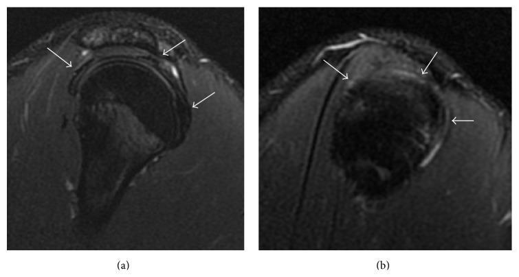
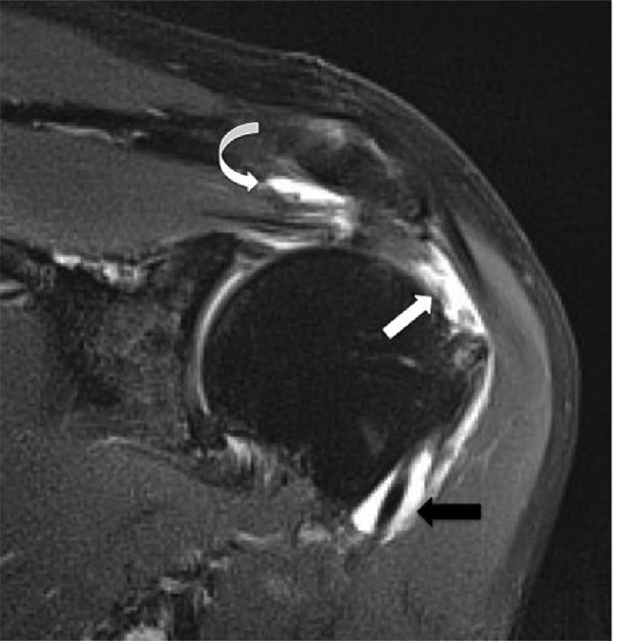
Two sagittal T2-weighted fat-suppressed spin-echo (T2 FS SE) magnetic resonance (MR) images of a right shoulder, labeled (a) and (b), focusing on the rotator cuff anatomy. The images demonstrate the supraspinatus, infraspinatus, and subscapularis tendons (indicated by white arrows) draped over the humeral head. The tendons exhibit characteristic uniform hypointensity and normal thickness, which are hallmark visual indicators of healthy, intact fibrocartilaginous tissue. There is a notable absence of hyperintense signal within the tendon substances or at their insertions, ruling out partial or full-thickness rotator cuff tears, tendinopathy, or significant inflammatory fluid collection in the subacromial-subdeltoid bursa. This diagnostic imaging serves as a clinical reference for normal musculoskeletal anatomy of the shoulder girdle and is used to evaluate the integrity of the rotator cuff in patients presenting with shoulder pain or limited range of motion.
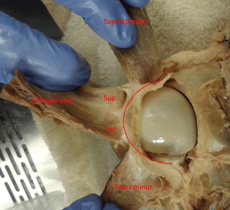
Anatomical Dissection: This clinical photograph provides a posterior view of a dissected left human shoulder, focusing on the rotator cuff complex. The supraspinatus, infraspinatus, and teres minor muscles are reflected laterally to reveal the underlying humeral head and its capsule. A curved red line overlay highlights the rotator cable, a thick fibrous band that spans the avascular zone of the rotator cuff. The infraspinatus muscle is further subdivided with labels 'Sup.' and 'Inf.', representing the superior and inferior portions of the muscle, respectively. The image demonstrates the varying degrees of adherence between the infraspinatus and the rotator cable, illustrating the functional anatomy of the shoulder's capsuloligamentous structures. This material is useful for studying musculoskeletal anatomy, specifically the insertions of the rotator cuff and the biomechanical role of the rotator cable in distributing forces across the shoulder joint.
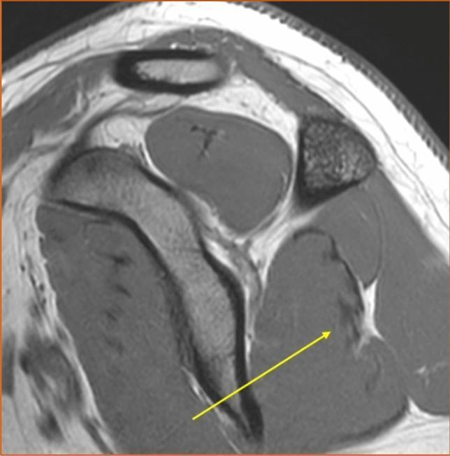
This T1-weighted sagittal MRI image displays a cross-section of the human shoulder, specifically focusing on the anatomical orientation of the rotator cuff muscles. The infraspinatus muscle is prominently featured, containing several low-signal (dark) bands representing intramuscular tendons. A yellow arrow points to a specific anatomical variant where these intramuscular tendons are judged as 'partly superficial.' Unlike tendons that remain entirely encased within the muscle belly, these structures extend toward and course along the posterior surface of the muscle. The high-contrast T1-weighted sequence allows for clear differentiation between the lower-signal dense fibrous connective tissue of the tendons and the relatively higher-signal intensity of the surrounding muscle fibers. This image serves as a clinical reference for identifying anatomical variations in the internal architecture of the infraspinatus, which is critical for understanding musculoskeletal biomechanics and potential sites for tendinopathy or tear propagation.
"rotator cuff"[MeSH Terms] AND repair
Rotator Cuff
Anatomy
| Muscle | Origin | Insertion | Action |
|---|---|---|---|
| Supraspinatus | Supraspinous fossa | Greater tubercle (superior facet) | Initiates abduction (0-15°) |
| Infraspinatus | Infraspinous fossa | Greater tubercle (middle facet) | External rotation |
| Teres minor | Lateral border of scapula | Greater tubercle (inferior facet) | External rotation |
| Subscapularis | Subscapular fossa | Lesser tubercle | Internal rotation |
Pathology
1. Impingement Syndrome
- Stage 1: Reversible edema and hemorrhage in the tendons
- Stage 2: Tendinopathy - collagen disorganization, mucoid degeneration, thickening
- Stage 3: Partial or full-thickness tear
2. Tendinopathy
3. Rotator Cuff Tears
- Advancing age (most common in >40 years)
- Rheumatoid arthritis, SLE (pannus invasion)
- Metabolic conditions: renal osteodystrophy
- Glucocorticoid use
- Trauma: fall on outstretched arm, heavy lifting
Clinical Presentation
- Pain with overhead activity, worse at night
- Painful arc of abduction (60-120°)
- Difficulty with activities of daily living (combing hair, reaching behind back, putting on a coat)
- Pain AND weakness of abduction and external rotation
- Crepitus; occasionally a palpable defect
- Chronic large tears: atrophy of supraspinatus and infraspinatus muscles, limitation of internal rotation from posterior capsular contracture
Diagnosis
Clinical Tests
- Neer's impingement sign: Pain with passive forward flexion
- Hawkins-Kennedy test: Pain with internal rotation at 90° flexion
- Drop arm test: Unable to slowly lower arm from 90° abduction (suggests full-thickness supraspinatus tear)
- Empty can (Jobe) test: Supraspinatus testing in the scapular plane
Imaging
- Size and shape of tear
- Degree of tendon retraction
- Presence of muscle atrophy (fatty infiltration - graded by Goutallier classification)
- LHB tendon status
- Bony abnormalities of the coracoacromial arch
Management
Conservative (Non-surgical)
- NSAIDs for pain and inflammation
- Ice/heat application; heat before stretching, ice after activity
- Physiotherapy (3-phase rehabilitation):
- Phase 1: Restore motion - pendulum exercises, passive stretching
- Phase 2: Strengthening cuff, deltoid, and scapular stabilizers
- Phase 3: Return to overhead work and sport
- Subacromial corticosteroid injections when pain prohibits rehabilitation (repeat every 3 months if needed; avoid direct tendon injection)
- Deep massage to reduce periscapular trigger points
Surgical
- Severity and duration of pain
- Degree and acuteness of the tear
- Functional disability and weakness
- Patient age, activity level, shoulder dominance
- Tendon retraction and fatty atrophy (indicators of repairability)
- Arthroscopic or open rotator cuff repair - primary repair with suture anchors to bone
- Subacromial decompression (acromioplasty) - if impingement is predominant
- Debridement - for massive irreparable tears; provides pain relief without restoring strength
- Tendon transfer or superior capsular reconstruction - for massive irreparable tears in active patients
- Reverse total shoulder arthroplasty - for cuff tear arthropathy with humeral head migration
Summary Table
| Feature | Tendinopathy/Impingement | Partial Tear | Full-Thickness Tear |
|---|---|---|---|
| Pain | Yes | Yes | Yes |
| Weakness | Mild | Mild | Marked |
| MRI signal | Increased T2 in tendon | Partial defect on one surface | Gap through full tendon |
| GHJ-SAB communication | No | No | Yes |
| First-line Rx | Physio + NSAIDs | Physio + NSAIDs | Physio; surgery if fails |
tell me about the ligaments present in knee joint
knee joint ligaments anatomy diagram ACL PCL MCL LCL
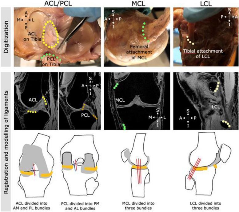
This composite educational image illustrates the multi-step process for digitizing and modeling human knee ligaments—ACL, PCL, MCL, and LCL—for orthopedic research. The top row features clinical photographs of cadaveric dissections where ligaments are digitized using anatomical landmarks: the ACL is highlighted as an oval area on the tibia, while the PCL, MCL, and LCL attachment sites are marked with colored point sequences. The middle row displays T1-weighted or Proton Density MRI scans in sagittal and coronal planes, showing the registration of these digitized points onto medical imaging to define ligamentous paths. The bottom row consists of schematic anatomical diagrams demonstrating the conceptual subdivision of ligaments into functional bundles: the ACL into anteromedial (AM) and posterolateral (PL) bundles; the PCL into posteromedial (PM) and anterolateral (AL) bundles; and the collateral ligaments (MCL and LCL) each into three distinct fiber bundles. This visualization supports biomechanical finite element modeling and the understanding of knee ligamentous stability and anatomy.
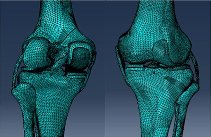
This image presents two views of a high-fidelity 3D computational model of a human knee joint featuring a Unicompartmental Knee Arthroplasty (UKA). The model is rendered using a complex triangular finite element mesh, providing a faceted visualization of the anatomical and prosthetic surfaces. The anatomy shown includes the distal femur, proximal tibia, and proximal fibula. Crucial soft tissue structures, including the anterior and posterior cruciate ligaments (ACL/PCL) and the medial and lateral collateral ligaments (MCL/LCL), are modeled as cable-like structures connecting the bony elements. The UKA is situated in the medial compartment, consisting of a metallic femoral condyle resurfacing component and a tibial baseplate platform. The model is designed for biomechanical stress analysis and surgical simulation, specifically investigating the impact of tibial component alignment and obliquity on load distribution. The teal-colored mesh highlights the geometry used for finite element analysis (FEA), demonstrating the interaction between the prosthetic implants and the native bone-cartilage complex.
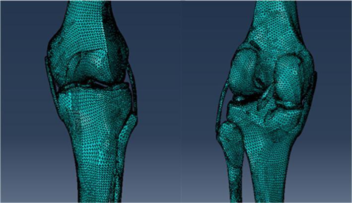
This diagnostic illustration presents two perspective views of a three-dimensional (3D) native human knee joint model. The visualization is a finite element or triangulated mesh representation derived from fused CT and MRI data. Anatomical structures shown include the distal femur, proximal tibia, and proximal fibula, with the mesh density clearly defining the cortical surfaces and contours. The model highlights soft tissue integration, specifically depicting the meniscus and the four major stabilizing ligaments: the anterior cruciate ligament (ACL), posterior cruciate ligament (PCL), medial collateral ligament (MCL), and lateral collateral ligament (LCL). The spatial relationships illustrate the tibiofemoral and proximal tibiofibular articulations. This digital model serves as a foundation for biomechanical simulations, such as Unicompartmental Knee Arthroplasty (UKA) planning and stress distribution analysis. The anatomical accuracy is tailored for orthopedic research and surgical education, emphasizing joint kinematics and structural integrity.
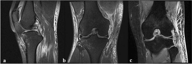
This set of three MRI images of the human knee joint illustrates combined ligamentous injuries. Image (a) is a sagittal view demonstrating an intraligamentous tear of the posterior cruciate ligament (PCL). The image shows discontinuity and high signal intensity within the PCL fibers, accompanied by peri-ligamentous edema. Image (b) is a coronal view displaying a medial collateral ligament (MCL) avulsion from its femoral attachment site, indicative of a posteromedial corner (PMC) injury. Image (c) is a coronal view highlighting a lateral collateral ligament (LCL) avulsion at the fibular attachment, representative of a posterolateral corner (PLC) injury. Both coronal images (b and c) reveal significant soft tissue edema and disruption of the normal dark, linear appearance of the collateral ligaments. These diagnostic images are essential for evaluating complex knee instability and planning surgical interventions such as PCL bracing or ligament augmentation.
Ligaments of the Knee Joint
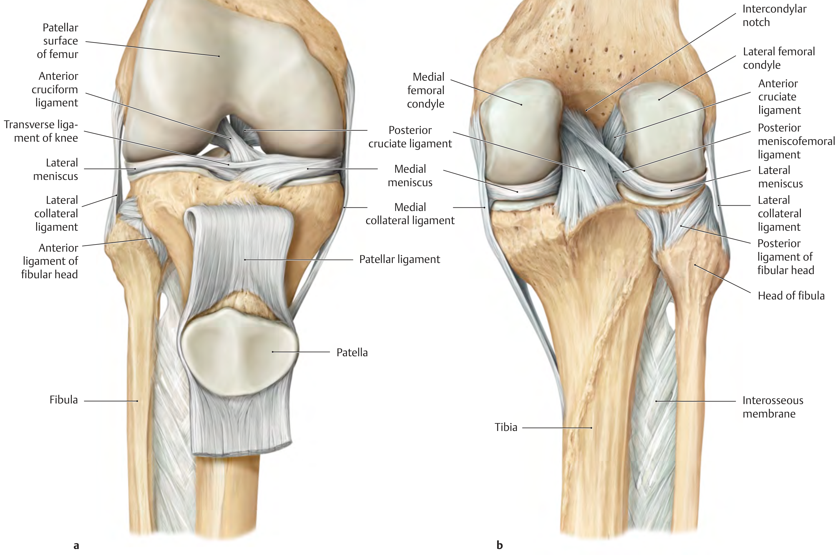
I. Intrinsic Ligaments (Intra-articular)
1. Anterior Cruciate Ligament (ACL)
| Feature | Detail |
|---|---|
| Femoral attachment | Posteromedial surface of the lateral femoral condyle (intercondylar notch) |
| Tibial attachment | Anterior intercondylar area of the tibia |
| Length / Diameter | ~30 mm / ~11 mm |
| Composition | 90% type I collagen, 10% type III collagen |
| Blood supply | Branches of the middle genicular artery + fat pad |
- Anteromedial (AM) bundle: Tight in flexion; primary restraint to anterior tibial translation; evaluated by the Lachman and anterior drawer tests
- Posterolateral (PL) bundle: Tight in extension; primary rotatory restraint; evaluated by the pivot shift test
2. Posterior Cruciate Ligament (PCL)
| Feature | Detail |
|---|---|
| Femoral attachment | Anterolateral surface of the medial femoral condyle |
| Tibial attachment | Posterior sulcus of the tibia (below articular surface) |
| Length / Diameter | ~38 mm / ~13 mm (thicker and stronger than the ACL) |
- Anterolateral (AL) bundle: Tight in flexion (mnemonic: PCL is your "PAL" - the important AL bundle is tight in flexion)
- Posteromedial (PM) bundle: Tight in extension
3. Meniscofemoral Ligaments (variably present)
- Ligament of Humphrey - passes anterior to the PCL
- Ligament of Wrisberg - passes posterior to the PCL
4. Transverse Ligament of the Knee (Transverse Meniscal Ligament)
II. Extrinsic Ligaments
5. Medial Collateral Ligament (MCL) - Tibial Collateral Ligament
Superficial MCL (sMCL)
- Femoral origin: Proximal and posterior to the medial femoral epicondyle
- Tibial insertion: Two separate attachments - proximal (soft tissue overlying semimembranosus) and distal (posteromedial tibia)
- Length: 100-120 mm
- Lies deep to the sartorial fascia, gracilis, and semitendinosus tendons
Deep MCL (dMCL) - Mid-third Medial Capsular Ligament
- A thickening of the medial joint capsule
- Has meniscofemoral and meniscotibial components
- Intimately associated with the medial meniscus
6. Lateral Collateral Ligament (LCL) - Fibular Collateral Ligament
| Feature | Detail |
|---|---|
| Femoral origin | Lateral epicondyle of femur |
| Fibular insertion | Lateral fibular head |
| Character | Cord-like; NOT attached to the lateral meniscus (unlike MCL to medial meniscus) |
7. Patellar Ligament
- Continuation of the quadriceps tendon below the patella
- Runs from the apex and lower pole of the patella to the tibial tuberosity
- Transmits quadriceps force to extend the knee
- Accompanied by medial and lateral patellar retinacula forming the anterior capsule
8. Oblique Popliteal Ligament
- Expansion of the semimembranosus tendon
- Passes obliquely from the posteromedial tibia upward to the lateral femoral condyle
- Strengthens the posterior capsule
9. Arcuate Popliteal Ligament
- Y-shaped ligament over the posterolateral corner of the capsule
- Arises from the fibular head, passes over the popliteus muscle, and attaches to the posterior tibia and lateral femoral condyle
- Part of the posterolateral corner (PLC) complex
III. Posteromedial Corner Structures
- Capsular thickenings of semimembranosus insertions
- Posterior horn of the medial meniscus
- Posterior Oblique Ligament (POL) - has three arms (superficial, central, capsular); the central arm inserts onto the posteromedial tibia; primary stabilizer against internal rotation between 0-30° flexion
- Oblique popliteal ligament
IV. Posterolateral Corner (PLC) Structures
| Structure | Function |
|---|---|
| LCL | Resists varus, tibial external rotation |
| Popliteus tendon | Primary restraint to tibial external rotation (especially in flexion); resists varus |
| Popliteofibular ligament | Runs from popliteus tendon to fibular styloid; resists tibial external rotation and posterior tibial displacement |
| Arcuate ligament | Posterior support |
V. Anterolateral Ligament (ALL)
VI. Medial Patellofemoral Ligament (MPFL)
| Feature | Detail |
|---|---|
| Femoral origin | Schottle point (between adductor tubercle and medial femoral epicondyle) |
| Patellar attachment | Junction of proximal and middle thirds of the medial patellar border |
| Length | 53-55 mm |
Summary Table
| Ligament | Attachments | Primary Function |
|---|---|---|
| ACL | Lat. femoral condyle → anterior tibia | Resists anterior tibial translation |
| PCL | Med. femoral condyle → posterior tibia | Resists posterior tibial translation |
| Humphrey / Wrisberg | Med. femoral condyle ↔ lat. meniscus | Stabilizes lateral meniscus |
| Transverse meniscal | Anterior horn medial ↔ lateral meniscus | Stabilizes menisci |
| Superficial MCL | Med. femoral epicondyle → proximal tibia | Resists valgus stress |
| Deep MCL | Capsular thickening | Resists valgus; anchors medial meniscus |
| Posterior oblique ligament | Posteromedial origin → posteromedial tibia | Resists internal tibial rotation |
| LCL | Lat. femoral epicondyle → fibular head | Resists varus stress |
| Popliteofibular ligament | Popliteus tendon → fibular styloid | Resists external tibial rotation |
| Patellar ligament | Apex patella → tibial tuberosity | Knee extension |
| Oblique popliteal | Semimembranosus → lat. femoral condyle | Resists hyperextension |
| Arcuate popliteal | Fibular head → posterior capsule | Posterolateral support |
| MPFL | Schottle point → medial patella | Resists lateral patellar dislocation |
| ALL | Lat. femoral epicondyle → anterolat. tibia | Resists internal tibial rotation |