
give a history of patient specific implant in maxillofacial reconstruction using standard references
patient-specific implant maxillofacial reconstruction history
history of patient specific implants maxillofacial surgery evolution timeline
PMID: 41055870
PMID: 26126124
CAD CAM custom implant craniofacial mandible reconstruction titanium
https://fomm.amegroups.org/article/view/54627/html
rapid prototyping stereolithography virtual surgical planning mandible reconstruction history
PEEK polyetheretherketone patient specific implant cranial orbit reconstruction
3D printing additive manufacturing titanium patient specific implant craniofacial
PMID: 35165240
bioprinting tissue engineering bone scaffold maxillofacial regeneration
History of Patient-Specific Implants in Maxillofacial Reconstruction
Definition and Scope
Era 1 (Pre-1970s): Empirical Hand-Crafted Customisation
- Gold and silver plates (1900s-1940s) for cranial defects - relatively inert but heavy and mechanically unreliable.
- Tantalum mesh (1940s-1950s) - introduced after World War II for cranial reconstruction; its malleability allowed intraoperative shaping.
- Acrylic (polymethylmethacrylate, PMMA) (1940s onward) - became popular for cranioplasty because it could be moulded by hand over a plaster skull model made from radiographs and then trimmed to fit; this represents the first systematic attempt to pre-make a patient-specific cranial implant.
Era 2 (1970s): Silicone, Anatomical Models, and the First True "Custom" Paradigm
Era 3 (1980s-Early 1990s): CT Imaging and the First Computer-Assisted Prototypes
- 3D CT reconstruction became feasible in the early 1980s, giving surgeons and prosthetists a true volumetric picture of defects for the first time.
- Stereolithography (SLA), invented in 1987 by Charles Hull, was quickly adopted in maxillofacial surgery. SLA uses UV-cured photopolymer resin to build a physical skull model layer by layer from CT data, allowing surgeons to pre-bend titanium plates, pre-form PMMA implants, and plan osteotomies on an accurate replica before entering the operating room. This was among the earliest uses of what would later be called rapid prototyping (RP) in surgery.
- By the early 1990s, centres in Germany and the US were using SLA-derived skull models to fabricate titanium mesh cranial implants, trimming and contouring them outside the body for a much better fit than was possible by intraoperative bending alone.
Era 4 (1994-2000): CAD/CAM Enters the Field - Titanium Takes Centre Stage
- 1994-1997: Groups in Germany (Scholz, Eufinger, Wehmoller) published the first systematic series of CAD/CAM-fabricated titanium implants for cranial and craniofacial defects [PMID: 9446459]. CT DICOM data was imported into CAD software, the implant was designed digitally, and then manufactured by computer-numerically-controlled (CNC) milling or casting - the first truly "digital" PSI workflow.
- 1998: Heissler and colleagues at Greifswald published their landmark series of custom-made cast titanium implants produced with CAD/CAM for cranial defect reconstruction [PMID: 9804194], demonstrating that CT-to-implant workflows were clinically viable and producing implants with superior fit compared to stock plates.
- 1999: A follow-up commentary confirmed the technique's clinical uptake across European neurosurgical and maxillofacial units [PMID: 10416903].
Era 5 (2000-2009): PEEK Emerges, Mirroring Algorithms, and Global Spread
Polyetheretherketone (PEEK)
Mirroring and Computational Planning
Free Flap Integration
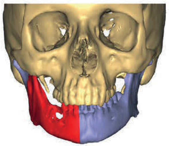
Era 6 (2009-2015): Virtual Surgical Planning (VSP), Cutting Guides, and the "Jaw-in-a-Day"
- Plan resection margins, fibula osteotomy lengths, and plate positions entirely on screen.
- 3D-print bone-mounted cutting guides and positioning jigs that physically constrained the osteotome to follow the planned cut.
- Pre-bend or pre-fabricate the titanium reconstruction plate to match the planned geometry.
Era 7 (2015-2020): Consolidation, PEEK Orbitals and Mandibles, and Commercial Ecosystems
Key developments:
- Orbital reconstruction with PEEK PSIs: PEEK became favoured for post-oncologic or post-traumatic orbital wall reconstruction because of its radio-transparency, lack of MRI artefact, ease of machining, and ability to be designed with porous surfaces. Goodson et al. (2012) described two-piece PEEK orbitozygomatic PSIs [PMID: 21700371], and Chepurnyi et al. (2020) demonstrated their clinical efficacy in orbital reconstruction [PMID: 32099771].
- Mandibular PEEK PSIs: Jarvinen et al. (2019, Helsinki) reported a series of PEEK PSIs for maxillofacial deformities, finding satisfactory outcomes with low complication rates [PMID: 31103433].
- Challenges identified: Alasseri and Alasraj (2020) reviewed challenges with PSIs - including implant exposure, infection, and manufacturing lead times - and proposed solutions such as antibiotic-loaded coatings and point-of-care (POC) printing [PMID: 32467823].
Era 8 (2020-Present): Additive Manufacturing, Point-of-Care, and Emerging Biologics
3D Printing (Additive Manufacturing) as the Manufacturing Paradigm
- Complex porous lattice structures that encourage osteointegration and reduce implant weight.
- Titanium alloy (Ti-6Al-4V) scaffolds with surface porosity tuned to ~200-600 µm for bone ingrowth.
- Faster prototyping cycles - weeks reduced to days.
Point-of-Care Printing
Novel Applications
- Post-mucormycosis reconstruction: The COVID-19 pandemic created a surge of extensive maxillofacial mucormycosis cases requiring large composite PSIs for palatal, orbital, and maxillary defects. Reddy et al. (2025) reported a case series of customised PSIs in this setting [PMID: 40756922].
- Scoping review (2025): Pai and Prabhu conducted a PRISMA-ScR scoping review (January 2015-January 2025) confirming that CAD/CAM and 3D printing facilitate anatomically precise PSIs, reduce surgical time, improve mastication and speech, and have low complication rates; no major differences in fit or longevity between milled and printed PSIs were found [PMID: 41055870].
Bioprinting and Tissue Engineering
Summary Timeline
| Period | Key Development |
|---|---|
| ~1920s-1940s | Hand-bent tantalum/gold plates; PMMA moulded over plaster models |
| 1976 | Mohler et al.: silicone custom implants over skull models (PMID 1259583) |
| 1982 | 3D CT reconstruction enters clinical use; Branemark's titanium implant legacy established |
| 1987 | Stereolithography invented (Charles Hull); skull models from CT data |
| 1997-1998 | Scholz/Eufinger/Heissler: first CAD/CAM titanium PSIs (PMIDs 9446459, 9804194) |
| 2000s | PEEK introduced as cranial/orbital PSI material; mirroring algorithms |
| 2009-2013 | VSP software + 3D-printed cutting guides + "Jaw-in-a-Day" |
| 2012 | PEEK orbitofacial PSIs (PMID 21700371); PEEK mandible mirroring (PMID 22258832) |
| 2015+ | Commercial PSI ecosystems; multi-material CAD/CAM platforms |
| 2019-2020 | PEEK mandible/orbital series; challenge literature |
| 2021-2022 | Metal additive manufacturing dominates; systematic reviews confirm superiority (PMID 35165240); point-of-care PEEK printing |
| 2024-2025 | Post-mucormycosis PSIs; scoping review (PMID 41055870); VR planning; bioprinting horizon |
Standard References (Cited Above)
- Mohler LR et al. Custom implants for reconstruction of craniofacial defects. Arch Surg. 1976. [PMID: 1259583]
- Scholz M, Eufinger H, Wehmoller M. CAD/CAM titanium implants for cranial/craniofacial defects. Zentralbl Neurochir. 1997. [PMID: 9446459]
- Heissler E et al. Custom-made cast titanium implants with CAD/CAM for cranium reconstruction. Int J Oral Maxillofac Surg. 1998. [PMID: 9804194]
- Heuser L et al. [Comment/letter on CAD/CAM cranial implants.] Int J Oral Maxillofac Surg. 1999. [PMID: 10416903]
- Scolozzi P. Maxillofacial reconstruction using PEEK PSIs by mirroring. Aesthetic Plast Surg. 2012. [PMID: 22258832]
- Goodson ML et al. Two-piece PEEK implants in orbitozygomatic reconstruction. Br J Oral Maxillofac Surg. 2012. [PMID: 21700371]
- Rohner D et al. Importance of patient-specific intraoperative guides in complex maxillofacial reconstruction. J Craniomaxillofac Surg. 2013. [PMID: 23228282]
- Owusu JA, Boahene K. Update of patient-specific maxillofacial implant. Curr Opin Otolaryngol Head Neck Surg. 2015. [PMID: 26126124]
- Jarvinen S et al. PEEK patient-specific implants for maxillofacial deformities. J Craniomaxillofac Surg. 2019. [PMID: 31103433]
- Alasseri N, Alasraj A. PSIs for maxillofacial defects: challenges and solutions. Maxillofac Plast Reconstr Surg. 2020. [PMID: 32467823]
- Chepurnyi Y et al. Clinical efficacy of PEEK PSIs in orbital reconstruction. J Oral Biol Craniofac Res. 2020. [PMID: 32099771]
- Sharma N et al. Point-of-care 3D-printed PEEK cranial implants. Int J Mol Sci. 2021. [PMID: 34445228]
- Ahmed KS et al. Implementation of 3D printing and CAD/CAM in craniofacial reconstruction - systematic review. J Craniofac Surg. 2022. [PMID: 35165240]
- Pai AG, Prabhu SS. PSIs for intraoral and maxillofacial reconstruction - scoping review. Maxillofac Plast Reconstr Surg. 2025. [PMID: 41055870]
- Bailey and Love's Short Practice of Surgery, 28th ed., p.848 (VSP and fibula free flap, Figure 53.10).
- Lee KC, Chuang SK. History of innovations in oral and maxillofacial surgery. Frontiers of Oral and Maxillofacial Medicine. 2022.
give a flowchart
A detailed vertical timeline flowchart showing the history of patient-specific implants in maxillofacial reconstruction. Each era is a box connected by arrows flowing downward. Include these eras in order: 1. PRE-1970s: Hand-Crafted Era — Hand-bent tantalum/gold plates, PMMA moulded over plaster skull models, carved ivory/silicone, World War I & II facial injuries drive innovation 2. 1970s: First Custom Implants — Mohler et al. 1976: silicone elastomer implants over anatomical plaster skull models (first dedicated "custom implant" report), methyl methacrylate cranioplasty pre-formed from skull models 3. 1980s–Early 1990s: CT Imaging + Stereolithography — 3D CT reconstruction enters clinical use (early 1980s), Stereolithography (SLA) invented 1987 by Charles Hull, SLA skull models used for pre-bending titanium plates, first rapid prototyping models in craniofacial surgery 4. 1994–2000: CAD/CAM Titanium PSIs — Scholz, Eufinger, Wehmoller 1997: first CAD/CAM titanium cranial implants, Heissler et al. 1998: custom-cast titanium CAD/CAM cranioplasty, CT-DICOM → CAD software → CNC milling/casting workflow established, Titanium (Ti-6Al-4V) becomes gold standard material 5. 2000–2009: PEEK + Mirroring Algorithms — PEEK introduced (elastic modulus ~3–4 GPa, near cortical bone), Contralateral mirroring algorithm for implant design, Commercial PEEK cranioplasty systems (KLS Martin, Stryker, DePuy), Pre-bent titanium plates over SLA models for fibula free flap mandible reconstruction 6. 2009–2015: Virtual Surgical Planning (VSP) + Cutting Guides — VSP software (ProPlan CMF, Simplant/Materialise), 3D-printed patient-specific cutting guides and positioning jigs, Rohner et al. 2013: intraoperative guides for complex reconstruction, "Jaw-in-a-Day" first described 2013 7. 2015–2020: Commercial PSI Ecosystems + PEEK Orbital/Mandible Series — Full commercial end-to-end PSI services, PEEK orbital wall and orbitozygomatic PSIs (Goodson 2012; Chepurnyi 2020), PEEK mandible series (Jarvinen et al. 2019, Helsinki), Challenges: implant exposure, infection, lead times identified 8. 2020–Present: Metal Additive Manufacturing + Point-of-Care Printing — Selective laser sintering / EBM porous titanium scaffolds, Systematic review 2022 (Ahmed et al.): 3D-printed PSIs outperform conventional (n=745), Point-of-care PEEK printing (Sharma et al. 2021), Post-mucormycosis PSIs (COVID-19 era), Scoping review 2025 (Pai & Prabhu): CAD/CAM and 3D printing validated 9. FUTURE HORIZON: Bioprinting + Tissue Engineering — Cell-laden scaffolds with BMP-2/PDGF, Living bone PSI replacements, Fully biologically integrated implants Use a clean medical/academic style with a navy blue and white color scheme. Each box should have the era title in bold and bullet points for key events. Arrows connect each box. The title at the top reads "History of Patient-Specific Implants in Maxillofacial Reconstruction". Include material icons (small symbols) for titanium, PEEK polymer, and 3D printing at relevant eras.
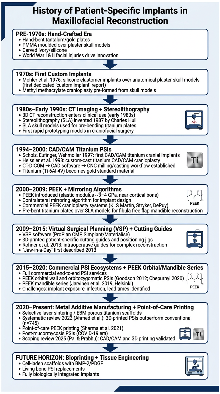
- The jump from plaster models → SLA skull models (1987) was the first time geometry became digitally captured rather than manually estimated.
- The CAD/CAM era (1994-2000) made the implant itself digital, not just the model.
- VSP + cutting guides (2009-2015) extended the digital chain all the way into the operating room.
- Additive manufacturing (2020s) closed the loop by making the fabrication process as flexible as the design software.
give a proper flow chart in shorter form and that which can be added in ppt which is esthetic and presentable
A clean, modern, presentation-ready horizontal timeline flowchart for a PowerPoint slide. Title at top: "Evolution of Patient-Specific Implants in Maxillofacial Reconstruction" in bold white text on a deep navy blue header bar. The flowchart has 6 milestone nodes arranged left to right connected by right-pointing arrows. Each node is a rounded rectangle with a colored top accent bar and white body. Use a gradient color scheme progressing from teal to blue to purple across the nodes. Node 1 — accent color teal: Icon: hammer/chisel symbol Era: "Pre-1970s" Title: "Hand-Craft Era" Text: "PMMA & tantalum plates moulded over plaster skull models" Node 2 — accent color cyan-blue: Icon: microscope symbol Era: "1970s–80s" Title: "CT & Stereolithography" Text: "3D CT imaging + SLA skull models for pre-operative plate bending" Node 3 — accent color blue: Icon: computer symbol Era: "1994–2000" Title: "CAD/CAM Titanium" Text: "First digital design → CNC-milled custom titanium cranial implants" Node 4 — accent color indigo: Icon: polygon/shape symbol Era: "2000–2009" Title: "PEEK & Mirroring" Text: "PEEK polymer implants; contralateral mirroring algorithm introduced" Node 5 — accent color violet: Icon: scissors/guide symbol Era: "2009–2015" Title: "Virtual Surgical Planning" Text: "VSP software + 3D-printed cutting guides; Jaw-in-a-Day procedure" Node 6 — accent color purple: Icon: 3D printer symbol Era: "2015–Present" Title: "Additive Manufacturing" Text: "Metal 3D printing, porous scaffolds, point-of-care printing, bioprinting horizon" Background: clean light grey (#F4F6F9). Arrows between nodes are thick, modern, gradient-colored chevron arrows. Nodes have subtle drop shadows. Typography is clean sans-serif (like Montserrat). Overall style: modern medical infographic suitable for academic PowerPoint presentation. Wide landscape 16:9 aspect ratio. Minimal text, maximum visual impact.
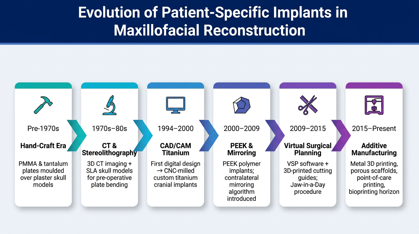
- Right-click the image → Save as PNG → Insert into your slide as a full-bleed image
- It sits well on a white or dark slide background
- Font size on each node is large enough to read from a projected screen