
Mapleson circuits in anesthesia
Reading File
Now let me search the medical library for Mapleson circuits content in parallel.
Finding Sources
Finding Sources
Searching the Web
Mapleson circuits anesthesia classification types fresh gas flow
Excellent - found rich content in three major anesthesia textbooks. Let me read all the relevant sections in parallel.
Reading File
Reading File
Reading File
Let me now read the remaining content from Morgan & Mikhail (performance characteristics) and Barash (Jackson-Rees), and fetch the key classification table image and circuit diagram.
Reading File
Reading File
Loading Image
Loading Image
I now have comprehensive content from three major anesthesia textbooks plus the key diagrams. Let me compile the full answer.
Mapleson Circuits in Anesthesia
Overview
Mapleson circuits (also called Mapleson breathing systems) are a group of semi-open, non-rebreathing anesthesia circuits first described by W.W. Mapleson in 1954. They consist of simple components arranged in different configurations - and it is the relative position of each component that determines circuit performance. A sixth system (F) was later added by Willis et al.
They differ fundamentally from the circle system in two ways: gas flow is bidirectional, and there is no CO2 absorber - CO2 elimination depends entirely on sufficient fresh gas inflow (washout).
Components
All Mapleson circuits share the same basic building blocks:
- Corrugated breathing tubes (22 mm diameter) - large bore to minimize resistance; also act as a gas reservoir. Volume should ideally equal or exceed the patient's tidal volume.
- Fresh gas inlet (FGI) - continuously supplies anesthetic gas mixture from the machine.
- Adjustable Pressure-Limiting (APL) valve - the "pop-off" or pressure-relief valve; vents excess gas and prevents pressure buildup.
- Reservoir bag - acts as a buffer for gas supply and allows manual ventilation (absent in Mapleson E).
- Face mask or ETT connection - patient interface.
The position of the FGI relative to the APL valve is the primary determinant of circuit efficiency.
- Morgan & Mikhail's Clinical Anesthesiology, 7e, p. 83-85
Classification Table
The six circuits (A-F) differ in component arrangement:
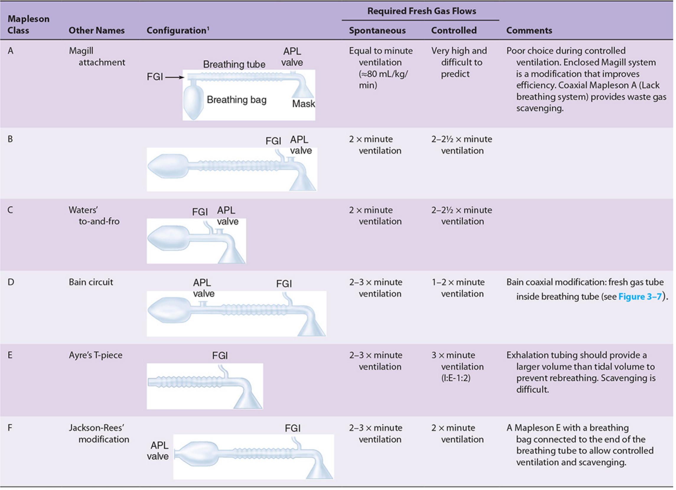
Table from Morgan & Mikhail's Clinical Anesthesiology, 7e
Gas Flow Diagrams (All Six Circuits)
The diagram below shows gas distribution at end-expiration for each circuit (blue = fresh gas, orange = dead space gas, red = alveolar gas):
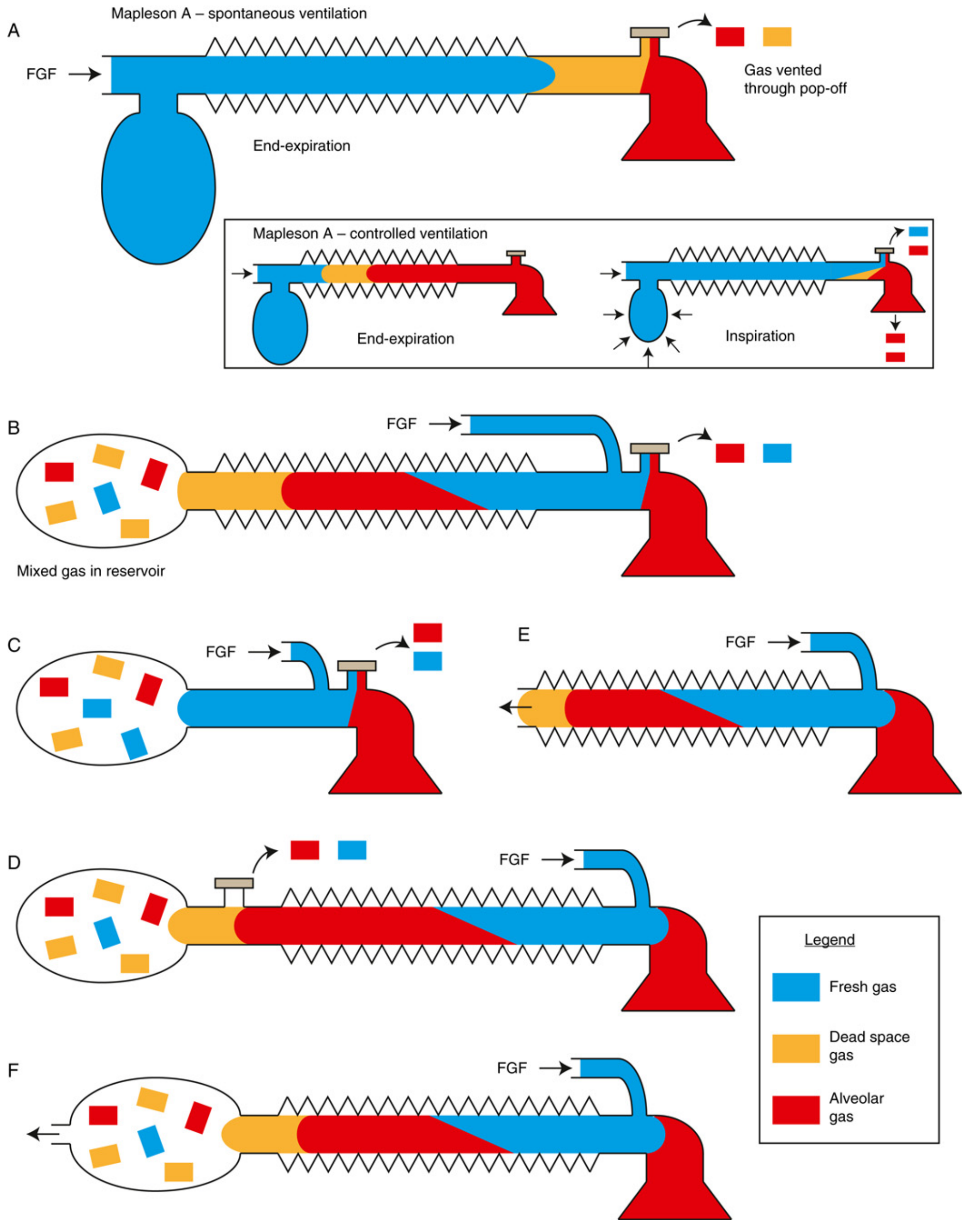
From Miller's Anesthesia, 10e (Fig. 20.38)
Individual Circuits
Mapleson A - "Magill Attachment"
- FGI at the bag end (far from patient); APL valve near the patient/mask.
- The only circuit where FGI is far from the patient.
- Spontaneous ventilation: Most efficient of all Mapleson circuits. FGF equal to minute ventilation (~80 mL/kg/min) is sufficient. During expiration, alveolar gas is vented through the APL valve, and fresh gas fills the tube before the next breath.
- Controlled ventilation: Least efficient - requires very high FGF (>3× minute ventilation) because the APL valve must be partially closed, preventing venting during expiration.
- Rarely used today for controlled ventilation; a poor choice for IPPV.
Mapleson B
- FGI and APL valve are both near the patient end.
- Spontaneous: 2× minute ventilation.
- Controlled: 2-2.5× minute ventilation.
- Mixed gas accumulates in the reservoir bag, making efficiency intermediate.
- Rarely used clinically.
Mapleson C - "Waters' To-and-Fro"
- Similar to B but lacks the corrugated reservoir tube (no breathing tube between bag and patient).
- Spontaneous: 2× minute ventilation.
- Controlled: 2-2.5× minute ventilation.
- Compact but dead space is a concern.
Mapleson D - "Bain Circuit" (coaxial modification)
- FGI near the patient end; APL valve near the bag (opposite of A).
- Functionally the mirror image of A.
- Spontaneous: 2-3× minute ventilation (less efficient than A for spontaneous).
- Controlled: 1-2× minute ventilation - most efficient of all Mapleson circuits for controlled ventilation. Fresh gas pushes alveolar gas away from the patient toward the APL valve.
- Bain circuit: A coaxial modification where the FGI tube runs inside the outer corrugated breathing tube. Benefits include: compactness, partial heat/humidity conservation (countercurrent exchange between warm expired and cool inspired gas). Key hazard: unrecognized kinking or disconnection of the inner tube causes hypercapnia. The Pethick test checks inner tube integrity.
Mapleson E - "Ayre's T-piece"
- A simple T-piece: FGI at the patient end, open-ended expiratory limb (no bag, no APL valve).
- No reservoir bag - only supports spontaneous ventilation (the only Mapleson without a bag). Used to liberate ICU patients from mechanical ventilation.
- Expiratory limb volume must exceed tidal volume to prevent rebreathing.
- Spontaneous: 2-3× minute ventilation.
- Controlled: ~3× minute ventilation (I:E ratio 1:2).
- Scavenging is difficult with this system.
Mapleson F - "Jackson-Rees Circuit"
- Mapleson E with a breathing bag added to the distal end, plus a valve to vent excess gas.
- FGI at the patient end; APL valve (or open tail) at the bag end.
- Primary pediatric circuit - low resistance, minimal dead space.
- The bag allows controlled ventilation and manual PEEP, plus monitoring of breathing by watching bag movement.
- FGF to prevent rebreathing: ~2.5× minute ventilation (same as Mapleson D).
- Also used for patient transport.
Functional Groups
Barash groups them into three performance clusters:
| Group | Members | Notes |
|---|---|---|
| Group A | Mapleson A | Best for spontaneous; worst for controlled |
| Group B/C | Mapleson B, C | Intermediate efficiency both modes |
| Group D/E/F | Mapleson D, E, F | Best for controlled; moderate for spontaneous |
- Barash Clinical Anesthesia, 9e, p. 2010
Key Performance Principle
"Simply moving components completely alters the fresh gas requirements."
- Morgan & Mikhail's Clinical Anesthesiology, 7e, p. 88
Memory aid for FGF requirements:
| Circuit | Spontaneous | Controlled |
|---|---|---|
| A | = MV (most efficient) | >3× MV (worst) |
| B, C | 2× MV | 2-2.5× MV |
| D, E, F | 2-3× MV | 1-2.5× MV (D/F most efficient) |
MV = minute ventilation (~70-80 mL/kg/min in adults)
Advantages of Mapleson Systems
- Lightweight, inexpensive, simple with few parts
- Low resistance to gas flow
- Rapid changes in FGF concentration translate quickly to the patient (no absorber)
- No CO2 absorber means no volatile anesthetic degradation (e.g., no compound A with sevoflurane)
- Small dead space (important in pediatrics)
Disadvantages
- Higher FGF required vs. circle systems - less economical, more waste gas
- Poor heat and humidity conservation
- Scavenging is challenging (especially Mapleson E)
- No rebreathing means higher volatile anesthetic consumption
- Risk of awareness if FGF is inadequate
Clinical Uses Today
-
Mapleson D / Bain: Still commonly used intraoperatively, especially for controlled ventilation; popular in the UK and Canada
-
Mapleson E / F (Jackson-Rees): Pediatric anesthesia, patient transport, ICU ventilator weaning
-
Mapleson A, B, C: Largely historic; rarely used in modern practice
-
All systems remain useful in resource-limited settings
-
Miller's Anesthesia, 10e, p. 2351-2353
-
Barash Clinical Anesthesia, 9e, p. 2010-2013
-
Morgan & Mikhail's Clinical Anesthesiology, 7e, p. 83-88
This is a shared conversation. Sign in to Orris to start your own chat.