
digital subtraction angiography
digital subtraction angiography DSA cerebral vascular imaging
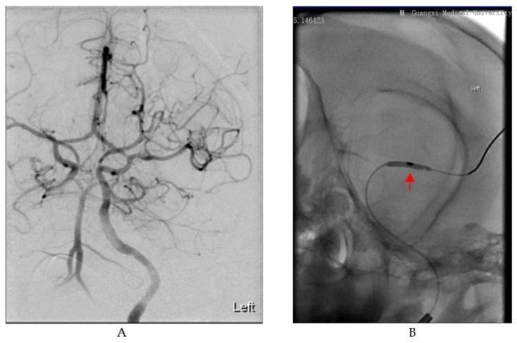
Digital Subtraction Angiography (DSA) of cerebral vasculature demonstrating endovascular stroke modeling. Figure A shows a baseline angiogram illustrating normal cerebral vascular anatomy, specifically the circle of Willis and its branching territories. The vessels appear as curvilinear, branching structures with smooth contours and uniform contrast opacification. Figure B captures an interventional procedure where a microcatheter and microguide wire are used to deploy a balloon. A red arrow identifies the inflated balloon catheter positioned within the M1 segment of the Middle Cerebral Artery (MCA). The balloon is visible as a radio-opaque, elongated distension causing temporary focal occlusion of the vessel to mimic an ischemic stroke event. This imaging serves as a demonstration of procedural neuro-intervention, focusing on the Middle Cerebral Artery (MCA) anatomy and the application of balloon-occlusion techniques for clinical or experimental modeling of ischemic cerebrovascular disease.
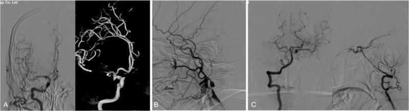
Cerebral digital subtraction angiography (DSA) images illustrating complex neurovascular pathology. Panel A shows a right internal carotid artery (ICA) angiogram in both standard and 3D reconstruction modes, revealing a saccular aneurysm at the posterior communicating artery (PCoA) segment. Panel B depicts the left carotid system, highlighting significant focal stenosis at the origin of the internal carotid artery, resulting in compromised distal contrast opacification and delayed perfusion. Panel C demonstrates left vertebral artery angiography, illustrating the posterior circulation and its involvement in the patient's vascular anomalies. The imaging series serves as a diagnostic tool for evaluating bilateral carotid artery communicating aneurysms and concomitant severe atherosclerotic stenosis. These findings are clinically significant in the context of neurosurgical planning for aneurysm clipping or endovascular coiling and stenting to mitigate the risk of subarachnoid hemorrhage and ischemic stroke.
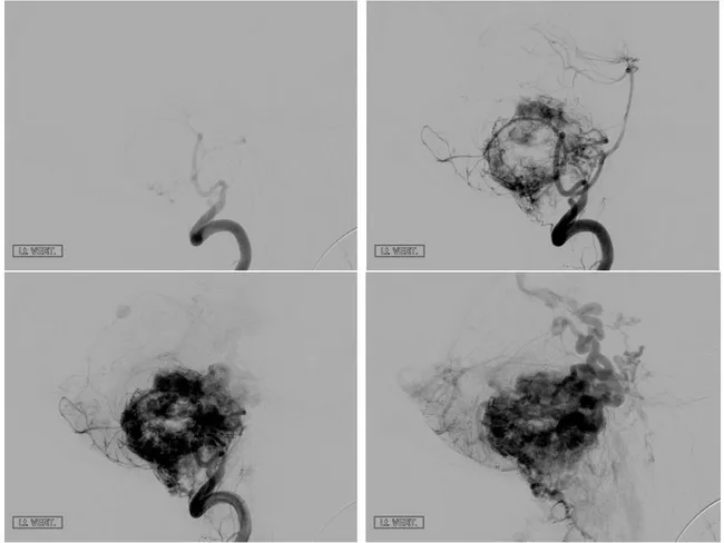
Imaging modality and technique: Cerebral Digital Subtraction Angiography (DSA) with selective vertebral and posterior circulation catheterization, featuring arterial, capillary, and venous phase acquisitions. The study targets a posterior fossa mass, most consistent with a cerebellar hemangioblastoma. The vascular tumor is hypervascular, with prominent feeding arteries and a conspicuous early draining venous plexus. In this case, large feeders arise from the posterior inferior cerebellar arteries and/or other cerebellar branches, producing a pronounced tumor blush that persists through the venous phase as a deep, densely opacified nidus. The peritumoral vessels are tortuous, and draining veins reach the tentorial or straight sinuses through a crowded venous network. The lesion is typically solid-cystic, well circumscribed, and can be extrinsic to the fourth ventricle; however, angiography emphasizes the vascular component. Radiographic differential considerations include other vascular cerebellar tumors such as pilocytic astrocytoma with vascularity and meningioma with sinus involvement in the posterior fossa, though meningiomas are less common in this location. Clinically, cerebellar hemangioblastomas are associated with von Hippel-Lindau syndrome in younger patients and can present with ataxia, headaches, and hydrocephalus from mass effect. The diagnostic significance lies in recognizing the characteristic arteriovenous pattern: multiple feeders, enlarged draining veins, and a deep tumor blush, guiding surgical planning or preoperative embolization decisions.
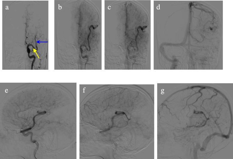
Digital subtraction angiography (DSA) of a left common carotid artery injection, displaying anteroposterior (AP, a–d) and lateral (e–g) views across multiple vascular phases. The imaging demonstrates a significantly enlarged and tortuous left middle cerebral artery (MCA). Key anatomical findings include multiple lateral striate arteries originating from the proximal M1 segment, a small vessel arising from the distal M1 segment (yellow arrow), and an additional branch originating from the proximal M2 segment (blue arrow). Hemodynamic characteristics show persistent visualization of the large MCA through the capillary phase (b, e), venous phase (c, f), and sinus phase (d, g), indicating delayed transit or slow outflow. Crucially, there is an absence of early venous drainage during the late arterial and capillary phases, which helps differentiate this arterial variation from high-flow arteriovenous shunts such as arteriovenous malformations (AVMs) or fistulas (AVFs).
digital subtraction angiography keep it pertaining to ent
DSA angiography glomus jugulare paraganglioma temporal bone ENT
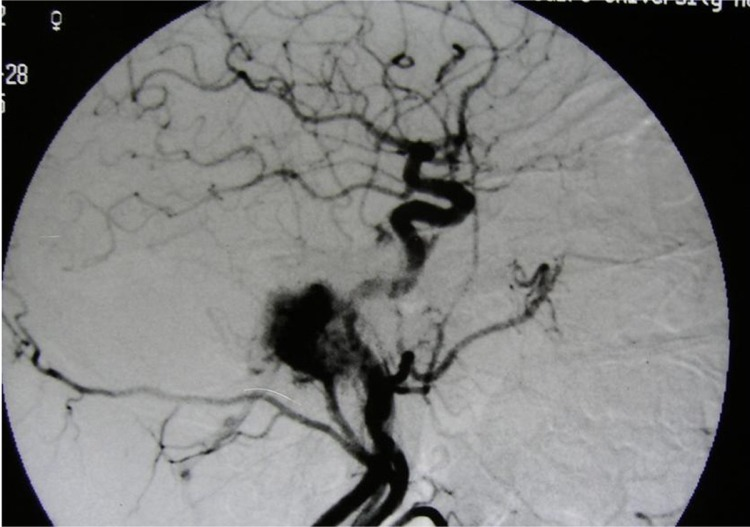
**Imaging Modality:** Digital Subtraction Angiography (DSA), lateral projection. **Anatomical Region:** Skull base and cervical carotid artery distribution. **Observed Pathology:** Glomus jugulare tumor (paraganglioma). The image demonstrates a highly vascularized, lobulated mass located at the level of the jugular bulb. **Characteristic Visual Features:** - **Tumor Blush:** A dense, intense, and persistent capillary opacification (blush) is evident during the arterial phase, characteristic of hypervascular skull base tumors. - **Arterial Supply:** Multiple hypertrophied feeding arteries are visible branching from the external carotid artery system toward the lesion. - **Mass Effect:** The lesion is situated in the posteroinferior aspect of the petrous temporal bone, adjacent to the carotid bifurcations and the internal carotid artery (ICA) siphon. - **Vascular Architecture:** Disorganized neovascularization within the tumor matrix, appearing as a "sunburst" or mottled enhancement pattern. **Key Diagnostic Features:** The location at the jugular foramen combined with the rapid, intense vascular blush on angiography is pathognomonic for a glomus jugulare tumor, differentiating it from less vascularized schwannomas or meningiomas in the same region.
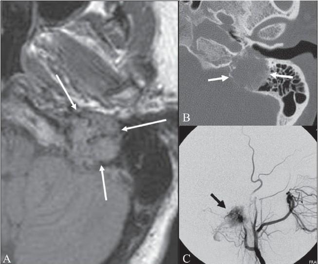
This composite educational image illustrates the diagnostic features of a glomus jugulare tumor (paraganglioma) within the left temporal bone through three imaging modalities. Panel A is an axial FLAIR MRI showing a heterogeneous, predominantly isointense mass in the jugular foramen region. It exhibits the characteristic 'salt and pepper sign,' where 'pepper' represents hypointense signal voids from high-flow vessels and 'salt' represents hyperintense foci from slow-flow vessels or hemorrhage. Panel B is an axial CT scan of the same anatomical region, highlighting the aggressive nature of the lesion through visible destruction and permeative erosion of the surrounding petrous temporal bone and jugular fossa (indicated by arrows). Panel C is an external carotid angiogram demonstrating a dense 'tumor blush' (black arrow), confirming the hypervascular nature of the mass. These multimodal findings—hypervascularity on angiography, bony destruction on CT, and the salt-and-pepper appearance on MRI—are pathognomonic for a glomus jugulare tumor. This content is intended for advanced medical education in neuroradiology and otolaryngology.
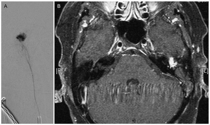
This dual-panel image displays diagnostic modalities for a Glomus tympanicum paraganglioma in a patient with pulsatile tinnitus. Panel A is a superselective Digital Subtraction Angiography (DSA) frame demonstrating a microcatheter positioned within a tortuous feeding vessel. A focal, irregular area of dense contrast opacification (tumor blush) is visible, indicating the hypervascular nature of the lesion prior to embolization. Panel B is an axial contrast-enhanced, fat-saturated T1-weighted Magnetic Resonance Image (ce-T1 fs MRI) of the skull base. It reveals a small, intensely enhancing soft tissue mass located in 'loco typico' within the left middle ear cavity, adjacent to the temporal bone. The mass is hyperintense relative to the surrounding brain parenchyma and musculature. These images illustrate the complementary roles of MRI for anatomical localization and DSA for vascular characterization of glomus tumors.
juvenile nasopharyngeal angiofibroma JNA DSA embolization angiography
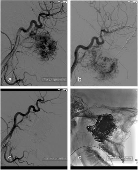
This composite of four lateral-view diagnostic images documents the preoperative embolization of a juvenile nasopharyngeal angiofibroma (JNA) via direct puncture. Image (a) is a pre-interventional digital subtraction angiography (DSA) showing a hypervascular tumor mass with dense pathological blush and disorganized vessel architecture. Image (b) captures the procedural stage, demonstrating the needle position during direct percutaneous puncture of the lesion for the administration of embolic agents. Image (c) presents the post-interventional control DSA, illustrating a marked devascularization of the tumor bed and the near-total disappearance of the previously visible vascular blush, confirming successful occlusion of the feeding vessels. Image (d) is a post-interventional radiograph without digital subtraction, showing the accumulation of radio-opaque embolic material within the tumor margins against the anatomical background of the skull base and facial bones. The series serves as an educational example of interventional neuroradiology techniques used to reduce intraoperative hemorrhage during subsequent surgical resection of benign but highly vascular head and neck tumors.
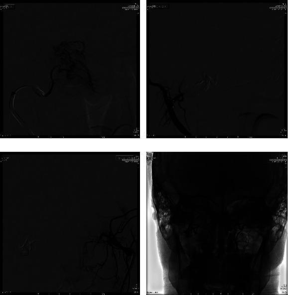
This composite of four images demonstrates the interventional radiology stages of preoperative embolization for a Juvenile Nasopharyngeal Angiofibroma (JNA). Panel (a) is an intraprocedural Digital Subtraction Angiography (DSA) in a posteroanterior (PA) view, showing superselective injection of the distal internal maxillary artery prior to embolization, highlighting the tumor's dense vascular blush. Panels (b) and (c) are post-procedural DSA images in a lateral-lateral (LL) view, illustrating the successful embolization of the lesion's right and left sides, respectively. These views show a near-complete absence of the previously noted vascular blush in the embolized territories. Panel (d) is a post-procedural fluoroscopy frame providing a wide view of the facial skeleton, confirming excellent technical results with the stabilization of the embolic agent (Onyx 18) within the feeder vessels. The primary educational focus is the use of endovascular techniques to achieve devascularization of a hypervascular skull base tumor to minimize intraoperative blood loss during subsequent surgical resection.
Digital Subtraction Angiography (DSA) in ENT
Principle
Role of DSA in ENT - Overview
- Mapping vascular supply of hypervascular tumors before embolization
- Guiding and monitoring embolization in real-time (road mapping)
- Post-embolization assessment - confirming devascularization
- Pre-operative occlusion testing (Balloon Occlusion Test / BOT) of the ICA
ENT Conditions Where DSA is Used
1. Glomus Jugulare Tumor (Paraganglioma)
- Ascending pharyngeal artery (most common; may be bilateral)
- Posterior division of the middle meningeal artery
- Stylomastoid branch of the occipital artery
- Posterior auricular artery
- If tumor extends to the foramen magnum: anterior/posterior meningeal branches of the vertebral artery
- Intradural extension: AICA/PICA branches
- Tumor encasing petrous/high cervical ICA: parasitized tiny ICA branches
2. Glomus Tympanicum Tumor
3. Glomus Vagale Tumor
- Ascending/deep cervical branches of the thyrocervical and costocervical trunks
- Neuromuscular branches of the ipsilateral vertebral artery
4. Juvenile Nasopharyngeal Angiofibroma (JNA)
- Internal maxillary artery and branches (ascending/descending palatine arteries) - primary supply
- Ascending pharyngeal artery (may be bilateral; may arise near the common carotid bifurcation, requiring CCA injection to visualize)
- Extracranial tumor with intracranial extension: vidian artery (from petrous/cavernous ICA), middle meningeal, accessory meningeal arteries
5. Carotid Body Tumor
Note: Some surgeons avoid preoperative embolization for carotid body tumors, arguing that the secondary inflammatory reaction can obscure surgical planes.
6. Epistaxis (Refractory / Recurrent)
- Selective external carotid artery angiography identifies the hypervascular bleeding site (e.g., superior nasal territory, sphenopalatine artery territory)
- Embolization with PVA particles (e.g., 150 µm) is performed under DSA road mapping
- Post-embolization DSA confirms occlusion of the distal internal maxillary artery and absence of the bleeding site
- Clinically effective in stopping recurrent epistaxis not amenable to endoscopic control
7. Meningiomas Involving the Skull Base / Paranasal Region
Balloon Occlusion Test (BOT)
- A balloon catheter occludes the ICA
- Clinical/neurological monitoring and cerebral blood flow assessment determine whether the patient can tolerate ICA sacrifice
- If BOT is passed, surgical ICA sacrifice or preoperative ICA occlusion with coils/detachable balloons can proceed safely
Technical Points Relevant to ENT
| Feature | Detail |
|---|---|
| Access | Transfemoral (standard); transradial alternative |
| Catheter size | 5-Fr for diagnostic; microcatheters for superselective embolization |
| Frame rate | 2-3 fps standard; 4-7 fps for AVM/high-flow lesions |
| 3D-DSA | 15-20 mL contrast at 3-5 mL/s via pump injector; produces rotational 3D vascular volumes |
| Embolization agents | PVA particles, Embospheres (100-500 µm); coils for vessel occlusion; Onyx for select cases |
| Provocative test | 1% lidocaine injected before embolizing CN VII-territory branches |
rhytidectomy
rhytidectomy facelift SMAS anatomy incision layers
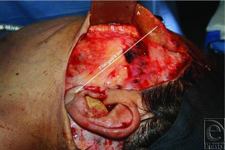
This intraoperative clinical photograph captures a surgical dissection during a deep-plane rhytidectomy (facelift) in the preauricular and temporal region. The image illustrates the anatomical relationship between tissue layers and the facial nerve. A skin flap, labeled 'A', is retracted superiorly, revealing the superficial musculoaponeurotic system (SMAS) layer, labeled 'B'. Deep to the elevated SMAS, the temporal (frontal) division of the facial nerve is identified by white arrowheads as it courses over the zygomatic arch (marked with arrows). A white annotation line represents Pitanguy's line, a surgical landmark extending from the tragus to a point 1.5 cm above the lateral eyebrow, used to estimate the trajectory of the frontal branch of the facial nerve. The photograph highlights an anatomical variation where the nerve emerges more posteriorly than typically reported. The surgical field includes the external ear with packing, local hemostasis, and surrounding surgical drapes. This visual is used to teach surgical anatomy, flap elevation techniques, and the importance of nerve preservation during aesthetic maxillofacial or plastic surgery.
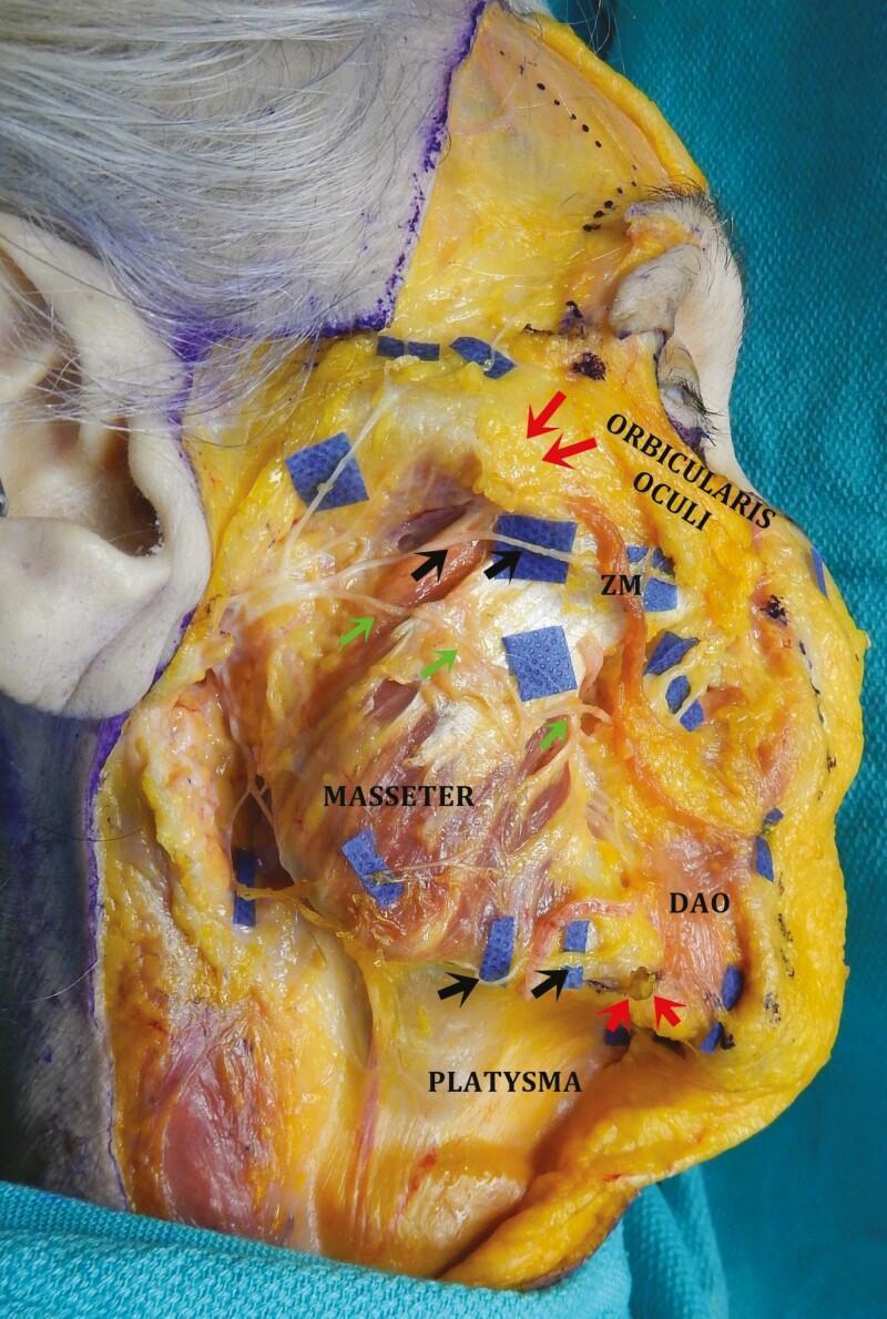
This clinical photograph displays a cadaveric dissection of the right hemiface, highlighting critical surgical anatomy for rhytidectomy (facelift). The skin and subcutaneous tissue are reflected medially, and the superficial muscular aponeurotic system (SMAS) and parotid gland have been removed to expose the underlying facial nerve branches and musculature. Key landmarks identified include the masseter, orbicularis oculi, zygomaticus major (ZM), platysma, and depressor anguli oris (DAO). Black arrows indicate the superior set (zygomatic branches) passing inferior to the zygomatic ligament (red arrow) into the 'sub-SMAS danger zone' deep to the ZM. Green arrows identify the buccal branches of the facial nerve. The inferior set of black arrows shows the marginal mandibular branch traveling past the mandibular osseocutaneous ligament (red arrow) to innervate the DAO on its deep surface. This visual serves as an educational guide for identifying facial nerve danger zones during deep-plane surgical dissection to avoid iatrogenic nerve injury.
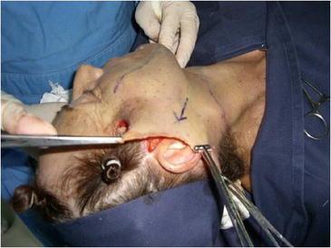
This intraoperative clinical photograph captures a key step in a rhytidectomy (facelift) surgical procedure. The image shows the facial and cervical region of a patient in a supine position, with the head oriented towards the left. A significant cutaneous flap has been undermined and is being retracted. Surgical instruments, including forceps and a retractor, are utilized by gloved hands to apply posterosuperior traction to the excess skin flap, following the tragus-Darwin’s tubercle line. Blue surgical markings, including an arrow indicating the primary force vector, are visible on the skin surface. The underlying subcutaneous tissue and SMAS (Superficial Muscular Aponeurotic System) layers are partially exposed near the preauricular area. This visual demonstrates the surgical management of skin laxity and the tension-free realignment of facial tissues during aesthetic or reconstructive surgery. The focus is on the biomechanical manipulation of the skin flap to achieve optimal redraping before excision of the redundant tissue.
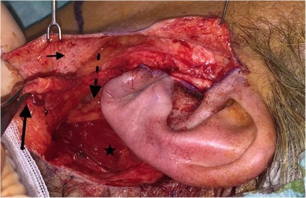
This clinical intraoperative photograph displays a left-sided parotidectomy field utilizing a modified facelift incision (MFI). The image illustrates the distinct surgical layers and anatomical structures exposed during the procedure. A thin superficial skin flap (indicated by a small horizontal arrow) is retracted superiorly using surgical hooks. Below this, a secondary, thicker flap consisting of the superficial musculoaponeurotic system (SMAS) is being manipulated with forceps (marked by a solid vertical arrow). Deep to the SMAS layer, the intermittent dashed arrow points toward the parotid capsule area. The sternocleidomastoid muscle (indicated by a star) is visible in the posterior-inferior aspect of the surgical bed. The ear is positioned centrally and slightly to the right of the dissection field, serving as a primary landmark for the MFI approach. The photograph demonstrates the anatomical plane between the subcutaneous tissue and the SMAS, as well as the surgical exposure of the parotid region required for tumor resection and subsequent reconstructive advancement of the SMAS flap.
Rhytidectomy (Facelift)
Definition and Goal
- Neck skin laxity (greatest improvement)
- Jowls
- Melolabial fold / nasolabial fold (MLF) - the most difficult to address
Anatomy of Facial Aging
| Structure | Changes with Aging |
|---|---|
| Skin | Decreased elasticity, increased laxity, epidermal thinning, dermal collagen disorganization, rhytids, actinic damage, telangiectasias |
| Periorbital | Lateral/inferior orbital rim shift, dermatochalasis, pseudoherniation of orbital fat, lengthening of lid-cheek junction |
| Midface | Descent of malar fat pad, nasolabial fold at rest, tear-trough deformity, posterior maxillary displacement |
| Jowl/Lower Face | Jowl formation, loss of jaw line definition |
| Neck | Effacement of cervicomental angle, platysmal banding, submental adiposity |
| Skeleton | Superomedial orbital rim remodeling, mandibular shrinkage, posterior maxillary displacement |
Key Anatomy - SMAS
- Fibromuscular structure superficial to the parotid fascia
- Begins inferiorly as the platysma in the neck
- Ends superiorly as the superficial temporal fascia (temporoparietal fascia)
- Anteriorly invests the mimetic muscles of the face (zygomaticus major/minor, orbicularis oris, orbicularis oculi, frontalis)
- Posterolaterally coalesces with the investing fascia of the SCM
- The facial nerve is always deep to the SMAS - this is the critical safety principle
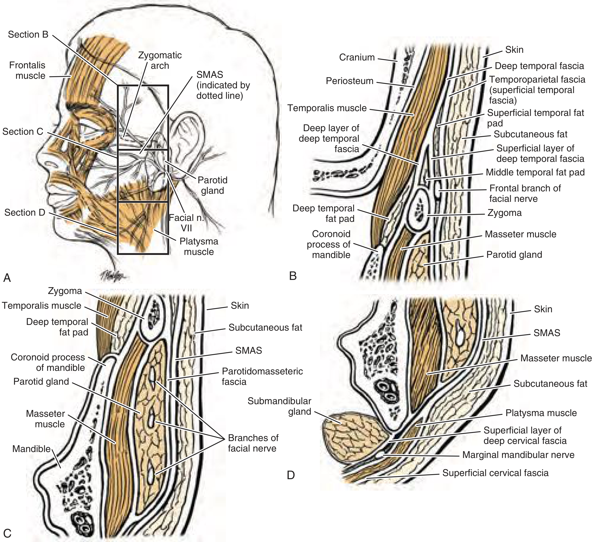
Facial Nerve - Danger Zones
- Temporal (frontal) - most commonly injured; exits the parotid superiorly, crosses the zygomatic arch within the superficial temporal fascia superficial to the periosteum
- Zygomatic
- Buccal
- Marginal mandibular - second most commonly injured
- Cervical
Historic Evolution
| Year | Milestone |
|---|---|
| 1901 | von Hollander performs first rhytidectomy (described 1912) - simple skin excision, no undermining |
| 1926 | Coronal incisions for forehead lifting introduced |
| 1970s | Skoog describes subfascial dissection - paradigm shift |
| 1976 | Mitz & Peyronie formally describe the SMAS |
| 1989 | Furnas describes midface retaining ligaments; release of zygomatic retaining ligament enables effective vertical SMAS lift |
| 1990s | Hamra perfects deep-plane rhytidectomy; later modifies to composite rhytidectomy (includes orbicularis oculi) |
| 1990s | Owsley describes extended supra-SMAS technique for midface fat repositioning |
Surgical Techniques
The Two Main Contemporary Techniques
| Feature | SMAS Rhytidectomy | Deep-Plane Rhytidectomy |
|---|---|---|
| Skin flap length | Longer (~6-7 cm) | Shorter (~3-5 cm) |
| Dissection plane | Subcutaneous + SMAS manipulation | Transitions to sub-SMAS at a shorter skin flap |
| SMAS handling | Plication (folded on itself) or imbrication (strip excised then sutured) | Released from zygomatic ligament, advanced as a musculocutaneous flap |
| Facial nerve risk | Lower | Higher (sub-SMAS dissection near nerve) |
| Hematoma risk | Higher | Lower |
| MLF improvement | Limited | Better |
| Midface | Less improvement | Releases zygomatic retaining ligament - better vertical lift |
Incision Planning
- Temporal hairline: curved to follow hairline; avoid placing superior to root of helix (unnatural "operated-on" look)
- Preauricular: follows the crease anterior to the helical cartilage
- Tragal:
- Female: posterior surface (posttragal), almost inside the canal
- Male: pretragal - to avoid advancing hirsute facial skin onto the hairless tragus
- Lobule: emerges inferior to the tragus, enters crease just anterior to the lobule
- Postauricular: follows posterior conchal cartilage, several mm anterior to the postauricular crease (fibrosis will eventually bring scar into the crease)
- Concha-mastoid junction: transition at right angle (avoid straight line - point of maximum tension)
- Occipital hairline: slightly rounded W-plasty incision (less conspicuous than linear scar)
Submentoplasty and Submental Liposuction
- Dissects submental neck skin from the underlying platysma/SMAS
- Allows adequate mobilization of the platysma for SMAS advancement
- Allows neck skin to be adequately advanced during redraping
- Cannula cutting edge faces away from dermis
- Gentle outward traction on dermis undersurface while suction draws fat into cannula
- Conservative approach - overly aggressive liposuction causes scar banding and cobra neck deformity
Skin Flap Closure
- Secure skin flaps at two points of maximal tension first (with staples):
- Junction of temporal hairline and preauricular incision
- Transition from postauricular to occipital scalp incision
- Tailor temporal scalp flap to match temporal hairline incision
- Leave posttragal skin flap slightly long (ensures incision stays posttragal after fibrosis)
- Leave some redundant skin at perilobular area to prevent satyr ear deformity (earlobe pulled inferiorly)
- Thin the tragal skin flap (excise subcutaneous fat) before closure to avoid a full, unnatural tragus
- Compression dressing applied
Postoperative Care
- Seen day 1: remove dressings and drains; inspect skin vascularity; assess for hematoma/seroma
- Minor seroma/hematoma (<10 mL): needle aspiration + compression dressing
- Cooling mask for 72 hours
- Showering allowed at 48 hours
- Suture/staple removal: preauricular sutures at day 7; remaining at day 10
- 4-week follow-up if healing well
- Photographs at 3 and 12 months
Complications
1. Hematoma (Most Common - 1-15%)
- Most common and most feared complication
- Major/expanding hematoma (within 24h): facial pain, excessive edema, ecchymosis - surgical emergency, return to OR for evacuation and hemostasis
- Minor hematoma (<10 mL): may be managed with needle aspiration in office
- Biggest risk factor: hypertension
2. Great Auricular Nerve Injury (Most Common Nerve Injury)
- Sensory nerve; numbness/paresthesia over lower auricle and earlobe
- Runs along posterior border of SCM - vulnerable during neck dissection
3. Facial Nerve Injury (Most Common Motor Nerve Injury)
- Branches most at risk: temporal, marginal mandibular, cervical
- Most injuries are neurapraxia - recover spontaneously
- Deep-plane techniques carry higher risk than SMAS techniques
4. Skin Flap Necrosis (1.1-3.0%)
- Usually result of untreated hematoma/seroma (subcutaneous fluid causes venous congestion)
- Smoking increases risk at least 12-fold - must stop smoking ≥2 weeks pre-op and ≥2 weeks post-op
- Other risk factors: diabetes, vascular disease, excessive wound closure tension, aggressive dissection
- Partial thickness: blue-black discoloration, desquamates, usually heals without scarring
- Full thickness: eschar formation, prolonged healing, hypertrophic scarring
- Management: conservative initially - necrotic tissue preserved as biologic dressing; debridement avoided early
5. Infection (<1%)
- Low incidence due to rich facial vasculature
- Organisms: Staphylococci (most common), then Streptococci
- Prophylaxis: chlorhexidine scrub, IV antibiotics within 60 min of incision, continue ≥24h post-op
- Consider MRSA if not responding to standard antibiotics
6. Aesthetic Complications
- Satyr ear deformity: earlobe pulled inferiorly - from insufficient skin redundancy left at lobule
- Cobra neck deformity: from over-aggressive submental liposuction
- Operated-on appearance: temporal incision placed too high (above helical root); hirsute tragus in males from pretragal incision not used
- Persistent melolabial fold
7. Situational Depression
- Common short-term psychological complication; patients should be counseled preoperatively